TEDA XQ140/12A User manual
MODEL XQ140/12A HYDRAULIC
POWER TONG
OPERATION MANUAL
2014-12
YANCHENG TEDA DRILLING AND PRODUCTION EQUIPMENT CO. ,LTD

Safety Instruction and Legend Description
Safety Instruction
●Operators must read and know this manual well.
●Operators must wear work uniform, safety shoes, safety helmet, safety gloves, etc.
●Tie the back guy according to the instruction. Don’t tie it in the wrong direction.
●Operation at the side of tong body opening.
●Don’t touch the running parts with hands when the tong is running.
●Don’t touch the running parts with hands when the tong is running.
●Keep sundries out of the working area.
●The pump should be off or the hydraulic tong power shut down as maintaining or hanging
the jaw plates, die seats or tong dies.
●Over-pressure and over-torque are forbidden.
●Don’t add or dismount any parts to the tong.
●Original parts made by should be used.
Legend Description
Serious Warning
Warning
Recommendation or Suggestion
Safety first, standard operation problems may occur if bugs are not rid of.

CONTENTS
1.Summary...........................................................................................................................................1
2.Structure characteristics and working principle.........................................................................................1
2.1 Transmission System......................................................................................................................1
2.2 Tong head assembly.........................................................................................................................2
2.2.1Clamping mechanism...................................................................................................................2
2.2.2 Braking mechanism...............................................................................................................................2
2.2.3 Reset mechanism............................................................................................................................3
2.2.4 Centralizing mechanism.......................................................................................................3
2.3Hydraulic system..................................................................................................................................4
2.3.1Hydraulic source..........................................................................................................................4
2.3.2Bucket valve ........................................................................................................................5
2.3.3Hydraulic lifting bucket.................................................................................................................5
2.3.4 Spring lifting bucket........................................................................ .....................................................6
2.3.5Hand control valve...................................................................... ..................................................6
2.3.6Hydraulic motor.................................................................... ..............................................................8
2.3.7Oil cylinder of backup tong....................................................... ................................................8
2.3.8 Hydraulic oil.......................................... .............................................. ........................................8
3.Main technical parameters.........................................................................................................9
4.Installing, Testing and Relative Requirement..........................................................................................9
4.1Check Before Installation....................................................................... ....................................................9
4.2 Lifting............................................................................................................................................9
4.3 Installing hydraulic pipeline......................................................................................................10
4.4 Installing the torque control system......................................................................................................10
4.5 Leveling.................................................................................................................................................10
4.6 Tie back guy.............................................................................................................................................10
4.7 Running-in operation ...........................................................................................................................11
4.8 Making-up or breaking-up operation..................................................................................................11
4.9Treatment after use.................................................................................. ....................................11
5.Detailed Operation Methods........................................................................ ........................................12
5.1Selecting And Dismounting Jaw Plate, Die Seat And Dies................................................................12
5.1.1Jaw plate selection............ ...............................................................................................12
5.1.2Die Seats Mounting /Dismounting.........................................................................................................13
5.2Adjusting the suspension height of the power tong with the hydraulic bucket.................................16
5.2.1Lifting the power tong........ ................... ........... ...................................................................................16
5.2.2lowering the power tong..... ....................... ........................................... ...............................................16
5.2.3Lock the height................................. ...........................................................................................16
5.3Connecting method of hoses.. ...................................................................................................................17
5.3.1Connecting the high pressure hose for oil inlet and outlet............................................................17
5.3.2Connecting hoses........................................... ......................... ............................................................17
5.4Installing the torque control system............................................................................................18
5.5 Filling oil into sensor cylinder......................................................................... ...................................19
5.5.1Sensor cylinder abstract............................................................................ ....................................19
5.5.2 Steps of filling oil into the cylinder.......................................................................................19

5.6Adjusting braking torque......................................................................................19
5.7Adjusting the space between master tong and breakup tong...........................................................20
5.8Making-up operation steps.......................... ......... ......... ................. ........ .....................................20
5.9Breaking-out operation steps................. ......... ........... .......................................................................21
5.10 Installing rack plunger............ ......... ......... .......................................................................................22
5.11Repairing gear disengagement......................................................................................22
5.12Gear shifting operation.................................................... ......................... .............................................22
5.13Testing torque......................................................... ......................... .............................................22
6.Maintenance................................................................. ......................... ...................................23
6.1Daily Maintenance..................................................... ......................... ..........................................23
6.2Monthly Maintenance.................................................. ......................... ........................................23
7.Common Troubles and Troubles Shooting Guide.................................................................................24
8.Portage, Storage And After Sales Service....................................................................................................25
8.1Portage......................................................................................................................................................25
8.2Storage..............................................................................................................................................25
8.3Unpacking..........................................................................................................................................25
8.4After Service ..........................................................................................................................................25
9.Attachment And Quick-wearing Accessory......................................... ..........................................26
9.1Optional Accessory..............................................................................................................................26
9.2Table of Quick-wearing Accessory....................................................................................................26
10.Figs and detail lists of parts....................................................................................................................27
10.1Combintion tong..........................................................................................................28
10.2Master tong.................................................................................................................29
10.3Tong shell and accessory..............................................................................................................30
10.4Mater tong head.....................................................................................................................32
10.5Resetting,braking and centralizing mechanism assembly............... ........... ...........................................34
10.6 Transmission mechanism.....................................................................................................................36
10.7Hand control valve................................................................... ....................................................39
10.8Gear shifting mechanism assembly(upper) .......... ........... ........... ........... ...........................................41
10.9Gear shifting mechanism assembly(lower) ............ ........... ........... ........... ..........................................42
10.10 Safety door assembly............................. ........... ........... ........... ........... ........... ........... ....................43
10.11 Backup tong............................................................ ........... ........... ........... ........................................44
10.12 Backup tong head..................................... ........... ........... ........... ........... ........... ........... ..................45
10.13Tail seat of backup tong......................................................................................... ...............................47
10.14Cylinder body of tong tail(optional part) ......... ........... ........... ........................................................49
10.15Hydraulic lifting bucket............................. .......................................................................................51
10.16Spring lifting bucket............................... ..............................................................................................53
10.17Lifting bucket valve........................ .........................................................................................54
10.18Front guide pole assembly............................................. ........................ ........... ................................55
10.19Rear guide pole assembly..............................................................................................................56
Model XQ140/12A HYDRAULIC SUCKER ROD TONG OPERATION MANUAL
YANCHENG TEDA DRILLING & PRODUCTION EQUIPMENT CO.,LTD
1
1.Summary
Model XQ140/12A hydraulic power tong is a mouth opening power tong which can quickly make-up or
break-out pipe strings in well service. It is used in making-up or breaking-out tubing, small drilling pipe
and small casing with diameters from 23/8″-51/2″ (60mm to 140mm). Compared with the same type of tongs
by other tong makers, it features simple structure, convenient operation, reliable performance, long life,
broad application range and large torque. It is widely used in onshore or offshore oilfields. It can reduce
workload, improve work efficiency and the well service quality.
2.Structure Characteristics And Working Principle
Hydraulic power tong consists of two main parts----master tong and backup tong. The backup tong clips
coupling or joints, (It can also clip the pipe body by lengthening the front and back guide poles as required.)
and the master tong clips pipe string, turns clockwise or counter-clockwise, in this way, it completes
making-up or breaking-out operations.
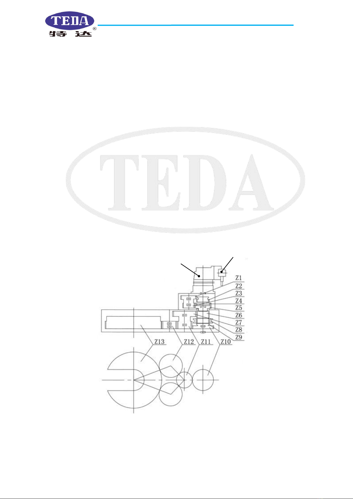
2.1 Transmission System
Hydraulic power tong has four shifts to reduce speed, as shown in figure 1.
Low Gear Engagement: Z2, Z1, Z3, Z5, Z6, Z7, Z11, Z12, Z13
Second Low Gear Engagement: Z2, Z1, Z3, Z5, Z10, Z11, Z12, Z13
Second High Gear Engagement: Z2, Z4, Z6, Z7, Z11, Z12, Z13
High Gear Engagement: Z2, Z4, Z8, Z9, Z10, Z11, Z12, Z13
Fig.1 Transmission diagram
Hydraulic motor
Hand control valve
Model XQ140/12A HYDRAULIC SUCKER ROD TONG OPERATION MANUAL
YANCHENG TEDA DRILLING & PRODUCTION EQUIPMENT CO.,LTD
2
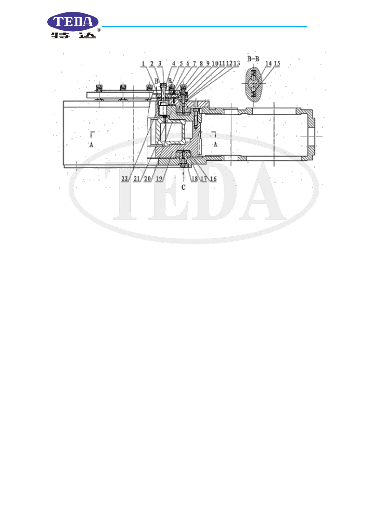
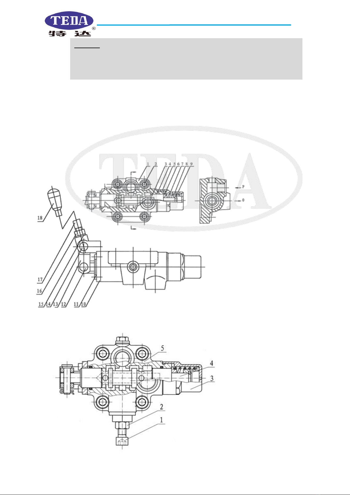
2.2 Tong Head Assembly (Fig.2, Fig.3, Fig.4)
Fig.2 Main View of Tong Head Assembly
1.stopper pin 2. reset knob axle 3.cylindrical pin 4.reset knob 5.spline connection plate
6.braking disc 7.slotted countersunk head screw 8.countersunk screw 9.friction disc
10.spring 11.braking plate 12. Lock nut 13. hexagon socket head screw 14.steel ball
15.spring 16.roller support frame 17.centralizing roller 18.centralizing roller axle 19.open
gear 20.jaw plate frame 21.open gear cover 22.spline plate
2.2.1 Clamping Mechanism (Fig.2, Fig.3)
The clamping mechanism adopts inner curved bilateral clamping mechanism. It consists of ramp plate,
roller, roller axle, jaw plate, die seats, tong dies and jaw plate frame assembly. The jaw plate frame
assembly is fixed in the inner side of the open gear. The spline on the board matches the spline on the
connection plate of braking mechanism. When the transmission system starts to drive the open gear to turn,
the jaw plate frame assembly doesn’t turn first at all under the braking force from the braking mechanism,
the curved ramp plate turns together with the open gear, the roller on the jaw plate climbs along the curved
surface of the ramp, moving jaw plate assembly towards the center, thus the preliminary clamping is
achieved.
As the torque increases and exceeds the braking moment, the open gear drives the spline connection plate,
braking disc, jaw plate frame assembly and the jaw plate in the braking mechanism to turn together with the
pipe string. The backup tong clamping mechanism is the same as that of the master tong. The hydraulic oil
drives rack plunger to make reciprocating movement and also drives the duplex gear and the jaw plate
frame to turn inside the main body of the backup tong, which drives the roller to climb, finally clips or
looses the pipe string.
2.2.2 Braking Mechanism (Fig.2)
Jaw plate frame assembly must be braked to drive roller and ramp to move in opposite directions (i.e.
climbing and resetting). The braking mechanism consists of braking plate, braking steel disc, spline
connection board, upper and lower friction disc, adjusting screw, spring and lock nut. It can change braking
moment by adjusting the compress force from the spring.
Model XQ140/12A HYDRAULIC SUCKER ROD TONG OPERATION MANUAL
YANCHENG TEDA DRILLING & PRODUCTION EQUIPMENT CO.,LTD
3
1.jaw plate frame
2.die seat
3.dies
4.ramp plate
5.jaw plate
6.roller axle
7.roller
8.cone point fastening screw
9.cylindrical pin
10.screw stopper
11.hexagon socket head screw
12.positioning screw
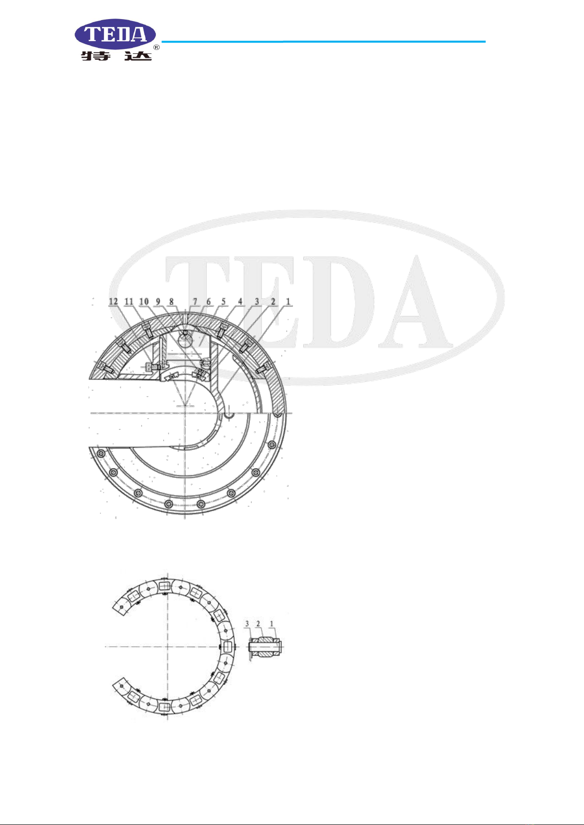
2.2.3 Reset Mechanism (Fig.3)
The initial working position of hydraulic power tong refers to the jaw plate frame and the open gear face
the opening of the shell body of the master tong, the jaw plate frame of the back-up tong faces the opening
of backup tong main body. The openings of master and backup tongs should be in alignment. After one
making-up and breaking-out operation ends, operate the hand control valve in the opposite direction to
return the hydraulic power tong to its initial working position, allowing the pipe string in or out through the
tong opening smoothly. During making-up and breaking-out, reset knobs on the master and backup tongs
should be in the same direction.
2.2.4 Centralizing Mechanism (Fig.2 and Fig.4)
The centralizing mechanism centralizes from up and down, inside and outside. It consists of roller
support frame, centralizing roller, centralizing roller axle and roller, which are respectively installed on the
shell body and the cover of the tong head. They match the open gear and the groove on the cover of the
open gear to guarantee the open gear turns along the original axle central line to avoid deflection and axial
running-out, thus the tong head is centralized.
Fig.3 A-A Cutaway View of Tong Head Assembly
Fig.4 Tong Head Assembly C-Side View
1.pin axle
2.roller
3.cotter pin

Model XQ140/12A HYDRAULIC SUCKER ROD TONG OPERATION MANUAL
YANCHENG TEDA DRILLING & PRODUCTION EQUIPMENT CO.,LTD
4
2.3 Hydraulic System
Hydraulic system consists of hydraulic source, bucket valve, hydraulic bucket, hand control valve,
hydraulic motor, hydraulic oil cylinder, pressure gauge, quick coupling, pipe line, etc.
Fig.5 Hydraulic System
Corresponding Relationship Between Input Pressure and Output Torque From Tong Head(Fig.6)
Fig.6 Corresponding Table Between Pressure and Torque
2.3.1 Hydraulic Source
It mainly provides high-pressure oil for power tong, which should be prepared by the users themselves.
1.Hydraulic Station
(1.1 Oil Pump; 1.2 Filter; 1.3 Anti-shock
Pressure Gauge; 1.4 Overflow Valve)
2.Anti-shock Pressure Gauge
3.Bucket Valve
4.Hydraulic Bucket
5.hand control valve
6.hydraulic motor
7.Backup Tong Oil cylinder
8.quick coupling

Model XQ140/12A HYDRAULIC SUCKER ROD TONG OPERATION MANUAL
YANCHENG TEDA DRILLING & PRODUCTION EQUIPMENT CO.,LTD
5
2.3.2 Bucket Valve
It consists of main body, throttle valve core, valve cap, handle, cutoff valve core, retaining ring, handle, oil
passage bolt, etc. Its main function is controlling the up or down of the piston rod of the hydraulic bucket.
Fig. 7 Bucket Valve
2.3.3 Hydraulic Lifting Bucket(see Fig.8, whether equipped hydraulic bucket or spring bucket depend on
customer. When equipped spring bucket not equip hydraulic bucket)
It consists of bucket body, cylinder, spring, piston rod, piston, throttle valve, joints, ect. (see Fig 8) Its main
function is to guarantee the free movement of the hydraulic power tong and adjust its suspension height in
making-up and breaking-out operation.(see the adjusting methods in 5.2) The stroke of the piston rod is 20
inches (508mm.).
Valve 1
Valve 2
1. axle-purpose retaining ring
2.nut
3. flat washer
4. main body of valve 5.handle
6.O-ring
7. flat washer
8. spring washer
9. nut
10. valve core
11. O-ring
12. O-ring
13. valve cap
14. spring washer
15.nut
16.flat washer
17.handle.
Hydraulic
pressure
remove bucket
1.hydraulic bucket
(1.1 Pin Axle 1.2 Cotter pin
1.3 suspension head 1.4 cotter pin
1.5 connector 1.6 O-ring 1.7
throttle valve core 1.8 cylinder
end connector 1.9bucket body
1.10 spring 1.12 piston rod 1.11
cylinder liner 1.13 O-ring 1.15
O-ring end connector 1.16
piston 1.17 hole-purpose
retaining ring 1.18 bucket end
connector)
2.copper shim
3. high pressure hose
4. bucket valve
5. quick coupler
6.copper shim
Fig.8 Hydraulic Bucket Assembly

Model XQ140/12A HYDRAULIC SUCKER ROD TONG OPERATION MANUAL
YANCHENG TEDA DRILLING & PRODUCTION EQUIPMENT CO.,LTD
6
2.3.4 Spring Lifting Bucket (see Fig.9, purchase number 14AZ-272 )
It consists of suspension head, suspension rod, spring, working bucket, etc, as shown in fig.9.
Its main function is to guarantee the free movement of the hydraulic power tong in making-up and
breaking-out operation.
Fig.9 spring bucket
2.3.5Hand control valve
Hand control valve falls into two types, one without pressure adjusting valve (purchase No. 12AZ-269, see
Fig.10-1),The other with pressure adjusting valve(Purchase No.12AZ-270.See Fig.10-2),either is available
according to the customer’s needs.
1.Pin axle
2.Cotter pin
3.Suspension head
4.Cotter pin
5.End cover
6.Spring
7.Auxiliary spring
8.Working bucket
9.Connector
10.Center rod
Suggestion:
●The pressure adjusting valve has been adjusted before delivery, never adjust randomly.
●The max torque of the low gear output may fail to reach 12KN.m in case the valve is
turned down.
Model XQ140/12A HYDRAULIC SUCKER ROD TONG OPERATION MANUAL
YANCHENG TEDA DRILLING & PRODUCTION EQUIPMENT CO.,LTD
7
Hand control valve without pressure adjusting valve consist mainly of valve body, valve core, spring,
handle, etc, see Fig.10-1.It mainly controls the direction of the hydraulic motor and the reciprocating
movement of the rack plunger.
Hand control valve with the pressure adjusting valve consist mainly of valve body, combination valve core,
spring, handle and pressure adjusting valve, etc, see Fig.10-2,loose nut 2 first when adjusting, drive the
hexagon socket bolt 1 in (clockwise) to turn up the limiting pressure, turn down the limiting pressure the
other way round. Read the needed pressure valve from the pressure gauge(Fig.5).Tighten nut 2 after
adjusting.
Fig.10-1 Handle control valve
Fig.10-2 Hand control valve
Warning:
●The hydraulic tong may be damaged of the valve is over turned.
●The pressure adjusting valve should never be adjusted without the system pressure
gauge.
1.valve body
2.hexagon socket head screw
3.combination valve core
4.O-ring
5.Valve tail seat
6.Spring seat(1)
7.Spring
8.Spring seat(2)
9.Locking plate
10.Support seat
11.Hexagon socket head
12.Pin axle
13.Shifting fork
14.Spring washer
15.Spring washer
16.Hexagon nut
17.Handle lever
18.Ball handle
1.Hexagon socket bolt
2.Nut
3.Valve tail seat
4.Combination valve core
5.Valve body

Model XQ140/12A HYDRAULIC SUCKER ROD TONG OPERATION MANUAL
YANCHENG TEDA DRILLING & PRODUCTION EQUIPMENT CO.,LTD
8
2.3.6Hydraulic motor
It is a low speed ,cycloid hydraulic motor with high torque. The model is 6K-625.
2.3.7Oil cylinder of backup tong(Fig.11)
It consists of cylinder liner, rack plunger, cover plate, Yx-sealing ring, cylinder cover etc. See Fig.11,high
pressure oil enters the cylinder liner through the cylinder cover, pushes the rack plunger to drive the duplex
gear and the backup tong jaw plate frame to move.
Fig.11 Oil cylinder of backup tong
2.3.8 Hydraulic Oil
The hydraulic oil used for power tong must be effectively filtrated to prevent sand, iron scraps entering to
guarantee the efficient oil usage. Oil filtration accuracy mustn’t be lower than 0.025mm (10min).
Recommended hydraulic oil is as follows:
(1)YC-N46 low temperature solidification hydraulic oil, the appropriate environmental temperature is
–20 ℃~+40 ℃;
(2)YB-N46 abrasion resistant hydraulic oil, the appropriate environmental temperature is -10 ℃~+40 ℃;
(3)YA-N46 hydraulic oil, the appropriate environmental temperature is 0 ℃~+40 ℃.
1.Tail part of main body of backup tong
2.Duplex gear
3.Rotating axle
4.Hexagon socket head screw
5.O-ring
6.Cylinder liner
7.Yx hole-purpose sealing ring
8.Cylinder cover
9.Cover plate
10.Hexagon socket head screw
11.Rack plunger
12.Hose joint
13.Oil passage bolt
14.Connector
15.O-ring
16.Quick coupling
17.connector

Model XQ140/12A HYDRAULIC SUCKER ROD TONG OPERATION MANUAL
YANCHENG TEDA DRILLING & PRODUCTION EQUIPMENT CO.,LTD
9
3.Main Technical Parameters
Main Technical Parameter of XQ140/12A Hydraulic Power Tong
1
Pipe string diameter suitable for main tong
mm
Φ60-140
inch
2 3/8″-5 1/2″
2
The biggest torque at low gear
kN•m
12
Ft-1bs
8851
3
The biggest torque at the second low gear
kN•m
7.8
Ft-1bs
5748
4
The biggest torque at the second high gear
kN•m
4.2
Ft-1bs
3095
5
The biggest torque at high gear
kN•m
2.6
Ft-1bs
1918
6
The highest speed at low gear
rpm
14
7
The highest speed at the second low gear
rpm
24
8
The highest speed at the second high gear
rpm
42
9
The highest speed at high gear
rpm
72
10
The max pressure of oil supply
MPa
12
psi
1740
bar
122
11
The max quantity of oil supply
Lpm
120
gpm
32
12
Weight (including backup tong)
kg
490
1bs
1080
13
Overall size (including backup tong)
(length×width×height)
mm
1036×621×841
inch
40.8×24.4×33.1
4.Installing, Testing and Relative Requirement
Installing procedures are as follows when hydraulic power tong is used on well site.
4.1Check Before Installation
●Check power tong damaged or not during transportation. If damaged, it
should be repaired.
●Check the fastening parts loose or not, tighten any loose parts.
●Check jaw plate, die seats and dies complete or not. (Fig.5.1)
4.2Lifting
4.2.1Lifting operation at the drilling rig or work-over rig is shown as Fig.12.
4.2.2Connect hydraulic bucket to the suspension bar of master tong by bolts.
4.2.3Install a pulley on the mast, which can bear load of 4400bf or more.
4.2.4Lift hydraulic power tong by a soft steel wire of 1/2″ or bigger, put this
wire through the pulley on the mast, one end connecting hydraulic bucket
and the other end fixed at the mast. Make dies of backup tong directly
Fig.12 lifting illustration

Model XQ140/12A HYDRAULIC SUCKER ROD TONG OPERATION MANUAL
YANCHENG TEDA DRILLING & PRODUCTION EQUIPMENT CO.,LTD
10
face the pipe string coupling or the drilling pipe tool joint(see detailed operation at 5.2) .
4.3 Installing hydraulic pipeline
See 5.3.1,5.3.2
4.4 Installing the torque control system(operation parts,
see 5.4)
4.5 Leveling(Fig.13)
●Push hydraulic power tong to the clamping position.
●Check whether tong head level or not. If it is not level,
keep master tong level by adjusting four screws on the
suspension bar. Check whether the backup tong parallel to
the master tong or not, if not, adjust them following the procedure of 5.6. Fig.13
4.6 Tie Back Guy (See Fig.14)
Back guy should be tied well after leveling the tong. One end of
the back guy should be tied to the pin axle at the tail of the tong;
the other end should be tied to the mast.
The height of the end of back guy tied to the mast should be
same as that of the tong. The back guy should be vertical with
the central line of tong body and also be pulled tightly.
Pay attention to the direction of the guy, the back guy should be
tied to the right hand side of the tong in the making-up operation,
but it should be on the left in the breaking-out operation when
observed from the front of the tong head. Don’t tie it in the
wrong direction(All above-mentioned are suitable for Right
Hand thread, as for Left Hand thread, on the contrary.)
●The support point of the pulley must be installed 15 meters above the well head.
●Central line of the power tong head is located at 0.6m away from the vertical line of
the well head in free suspension state.
●Avoid breaking the hose due to twisting in use.
●The piston rod extends and faces downward when installing the bucket.
●When the backup tong directly faces the pipe string coupling or the drilling pipe joint,
the piston rod of the bucket should be located at half of the stroke.
●The suspension height of the hydraulic tong can be adjusted easily with the hydraulic
bucket.
●Power tong leveling is very important, if not level, the tong head clamping will fail to
work.
●Four screws should be adjusted in coordination.
Fig.14 Illustration of black guy
Left
Right
Breaking-out direction
Making-up direction
●Back guy, which is usually soft wire rope, must be able to bear load of over 6600bf.
Adjusting bolt
Model XQ140/12A HYDRAULIC SUCKER ROD TONG OPERATION MANUAL
YANCHENG TEDA DRILLING & PRODUCTION EQUIPMENT CO.,LTD
11
4.7 Running-in Operation
●Supply hydraulic power tong with oil.
●Control the lifting bucket; adjust the height of power tong.
●Keep free-load running at low gear for 1 to 2 minutes.
●Keep free-load running at high gear for 1 to 2 minutes.
●Test tong head running in clockwise and counter-clockwise directions, watch whether master tong and
backup tong being synchronous or not. Adjust the direction of reset knob if they are not synchronous.
●The adjusting procedure is shown at 5.4.
●Open the safety door, deliver tong to the well head, watch whether the space between master tong and
backup tong suitable or not. Adjust the space between them if not suitable.
●Try to clamp the pipe string at high gear, adjust system oil supply pressure by adjusting the overflow
valve in the hydraulic system according to the table of the making-up torque value, shifts, torque and
pressure parameter (See Fig.6) recommended by API.
Note: Being synchronous means both the master tong dies and the backup tong dies and the backup tong
dies stretch out when operating the hand control valve in one direction. When operating hand control valve
in the opposite direction, the jaw plate frame of the master tong and the opening gear face the opening of
master tong, the jaw plate frame of the backup tong and the main body of backup tong, too. The reason for
being non-synchronous are:1.the wrong direction of the reset knob; 2.wrong connection of the hoses of the
backup tong is sure to slip, see 5.3.2 for the right connection method.
4.8 Making-up or breaking-up operation
See 5.7, 5.8 for recommended steps.
4.9 Treatment after use
Operate as the following procedures after the work is finished.
●Cut off power source.
●Remove the high-pressure hose.
●Protect oil inlet and outlet to prevent sand or iron scraps getting in.
●Check fastening parts, fasten the loose parts.
●Put down power tong, place it in an even place, otherwise the tong will be damaged if the place is not
even.
●Clean and maintain power tong as (6).
●Don’t disassemble hydraulic pipe at high pressure, otherwise, accidents may occur and
the equipment may be damaged.
●Don’t approach the running part of hydraulic power tong by your body or clothes.
●Only operators are allowed to approach hydraulic tong to avoid any trouble caused by
turning the operating lever.
●The hand control valve may be slightly operated to realize gear shifting at low gear to
avoid damaging the gear.
●The temperature of the hydraulic oil should not be over 65℃.Over heating can make
hydraulic system seal fail to work and slow down the running speed of tong.
●Proper treatment prolongs the life of power tong after use.
Model XQ140/12A HYDRAULIC SUCKER ROD TONG OPERATION MANUAL
YANCHENG TEDA DRILLING & PRODUCTION EQUIPMENT CO.,LTD
12
5.Detailed Operation Methods
5.1 Selecting And Dismounting Jaw Plate, Die Seat And Dies
(state any special specification in your order)
5.1.1Jaw plate selection
(1)Jaw plate specification(see Fig.15, three kinds in all, one kind of master tong jaw plate, two kinds for
backup tong jaw plates)and parts number are shown in table 1.
Fig.15
Table 1 Die Seat Specification
Serial No.
Purchase No.
Drawing name
Part name
Notes
1
12AZ-111
XYQ12.Z-01.9
Jaw plate
Used for master tong, suitable for
all adaptive pipe diameters.
2
12AB-28.1
XYQ12.B-11(1)
Jaw plate(1)
Used for backup tong, suitable
for all adaptive casings except the
casing ofΦ140mm(5 1/2″)
3
12AB-28.2
XYQ12.B-11(2)
Jaw plate (2)
Used for backup tong, suitable
only for the casing coupling of
Φ140mm(5 1/2″)
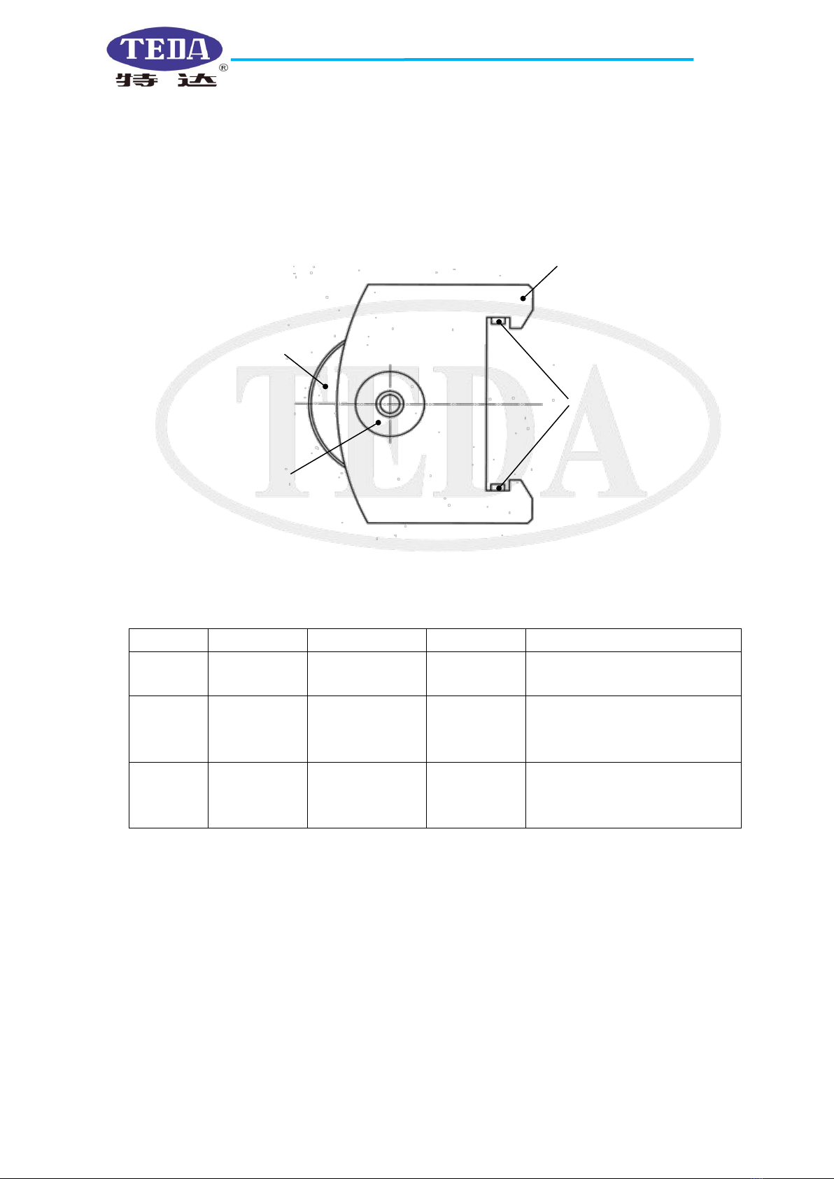
(2)Jaw plate assembly and its mounting /Dismounting
●Jaw plate assembly consists of jaw plate, roller, roller axle and stopper pin etc.
●When dismounting jaw plate, take out two die seats first, then turn the tong head, expose the positioning
screw on the jaw plate frame from the opening of the tong head, loose the positioning screw, then the jaw
plate can be taken out from the center of the tong head.
●Mounting operation procedure is just on the contrary (See Fig.16)
Jaw plate
Stopper pin
Roller
Roller axle
Model XQ140/12A HYDRAULIC SUCKER ROD TONG OPERATION MANUAL
YANCHENG TEDA DRILLING & PRODUCTION EQUIPMENT CO.,LTD
13
Fig.16
5.1.2 Die Seats Mounting /Dismounting
(1)Specification and parts number of die seats(11 kinds in total,
one kind is especially for backup tong) and dies(three kinds in all,
suitable for both master tong and backup tong).
This power tong clamp pipe string of different outside diameters
by changing die seats and dies of different specifications. The die
`seats and dies are equally useful for master and backup tongs
when clamping pipe strings of the same outside diameter. When
selecting die seat and dies, refer to the stamp marks and part
numbers on their back.
Die seats specification and part number are shown in table 2.
Dies specification and part numbers are shown in table 3.
(2)Recommendation table of die seats and dies (see table 4)
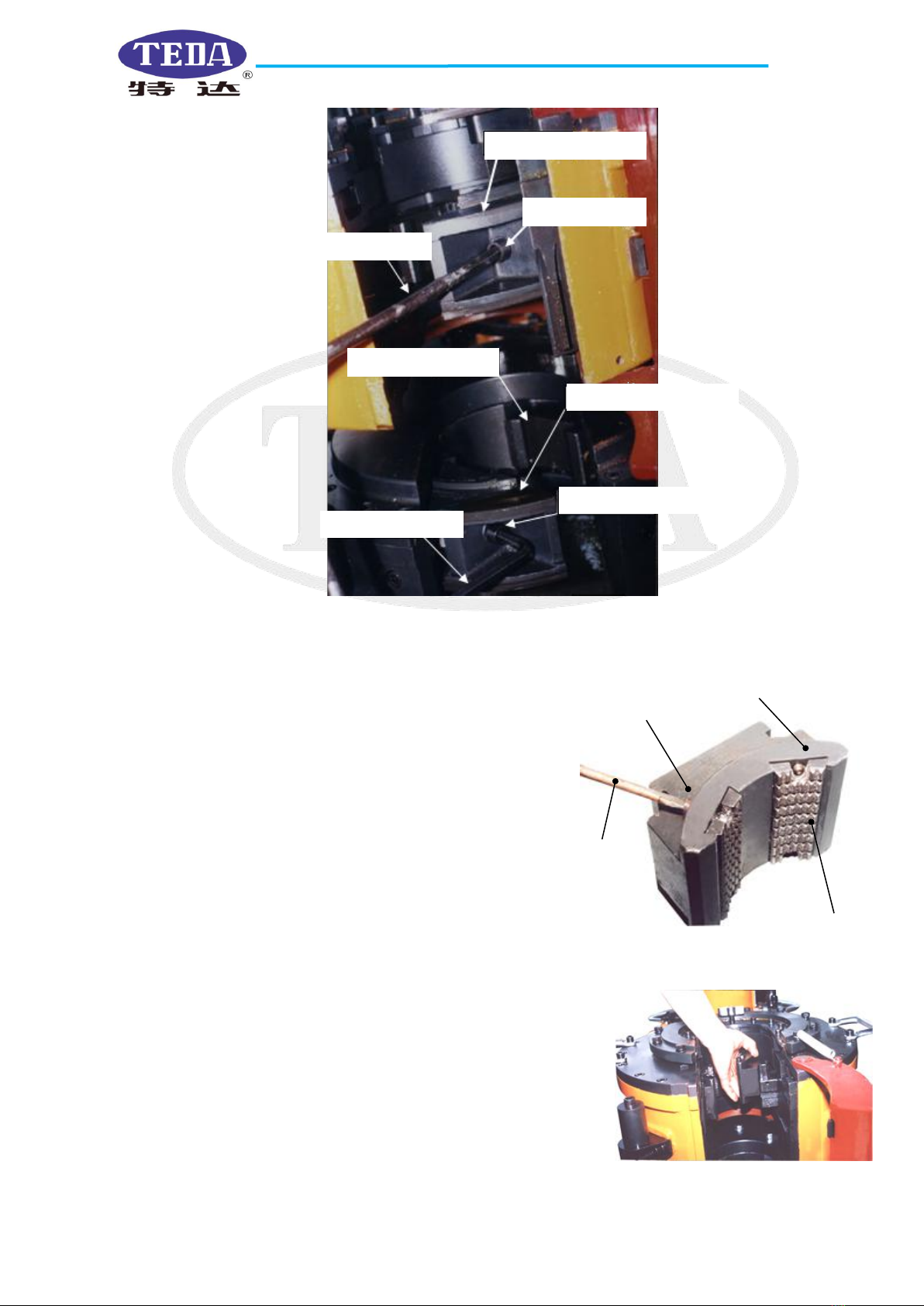
(3)Die seats assembly and mounting/dismounting
Die seats assembly consists of die seats and screw stopper(see Fig.17)
Dismounting die seat assembly: pull one die seat assembly to the center
of tong head, lift it upward out of tong head directly, take out the other
one in the same way. Mounting operation is the other way round(see
Fig.18).
Jaw plate of master tong
Positioning screw
Hexagon socket wrench
Jaw plate of backup tong
Jaw plate of backup tong
hexagon socket wrench
Stop screwe
Fig.17
Screw stopper
Screw driver
Die seat
Dies
Fig.18
Model XQ140/12A HYDRAULIC SUCKER ROD TONG OPERATION MANUAL
YANCHENG TEDA DRILLING & PRODUCTION EQUIPMENT CO.,LTD
14
(4)Dies mounting/dismounting
Take out die seat and loose the screw pin on one end, then take out dies. Mounting operation is the other
way round, tighten the screw pin after mounting(see Fig.15)
Table 2 Die seat specification
Table 3 Dies specification
Series No.
Purchase No.
Part name
Mark (steel mark)
Note
1
12AZ-110.1
Die (1)
12A(73-78)
Can be used for 60 string
2
12AZ-110.2
Die (2)
12A(89-114)
3
12AZ-110.3
Die (3)
12A(121-156)
Series No.
Purchase No.
Part name
Mark (steel mark)
Note
1
12AZ-107.1
Die seat(1)
12A(138-143)
2
12AZ-107.2
Die seat(2)
12A(128-132.5)
3
12AZ-107.3
Die seat (3)
12A(122-127)
4
12AZ-107.4
Die seat (4)
12A(116-121)
5
12AZ-107.5
Die seat (5)
12A(109-114)
6
12AZ-107.6
Die seat (6)
12A(102-107)
7
12AZ-107.7
Die seat (7)
12A(86-93)
8
12AZ-107.8
Die seat (8)
12A(70-73)
9
12AZ-107.9
Die seat (9)
12A(78)
10
12AZ-107.10
Die seat (10)
12A(60)
11
12AB-29
Die seat
12A B(151-156)
For backup tong only
●The hydraulic power source must be cut off when changing jaw plates, die seats and
dies.
●Die seats and dies must be cut off when changing jaw plates, die seats and dies.
●Die seats and dies must be changed in pairs.
●Refer to the steel mark on the die seat and dies for the specification.
●5 1/2″casing can be mounted or dismounted with 143-148 die seats for master tong(jaw
plate remain the same ) and 156-151 die seats and jaw plate (2) for backup tong.
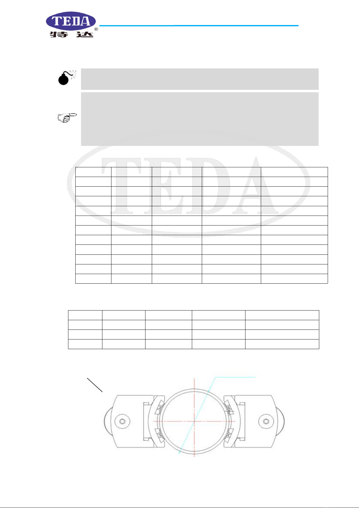
Fig.19 Clamping illustration
Pipe string
Die plate assembly
Assembly of jaw plate
Dies
Φ pipe outer diameter mm (in)
Jaw plate
Jaw plate roller
Roller axle

Model XQ140/12A HYDRAULIC SUCKER ROD TONG OPERATION MANUAL
YANCHENG TEDA DRILLING & PRODUCTION EQUIPMENT CO.,LTD
15
Table 4 Recommendation table of die seats and dies (see Fig.19 for illustration)
Pipe string type
O.D
mm(inch)
Die seat (stamp mark)
Dies (stamp mark on the
backside)
Master tong
Backup tong
Master tong
Backup tong
Tubing
60( 2 3/8″)
12A(60)
12A(70-73)
12A(73-78)
12A(73-78)
Tubing
73( 2 7/8″)
12A(70-73)
12A(86-93)
12A(73-78)
12A(89-114)
Tubing
89(3 1/2″)
12A(86-93)
12A(102-107)
12A(89-114)
12A(89-114)
Tubing
102(4″)
12A(102-107)
12A(116-121)
12A(89-114)
12A(89-114)
Tubing
114(4 1/2″)
12A(109-114)
12A(128-132.5)
12A(89-114)
12A(121-156)
Tubing (EU)
73(2 7/8″)
12A(70-73)
12A(86-93)
12A(73-78)
12A(89-114)
Tubing (EU)
89(3 1/2″)
12A(86-93)
12A(109-114)
12A(89-114)
12A(89-114)
Tubing (EU)
102(4″)
12A(102-107)
12A(122-127)
12A(89-114)
12A(121-156)
Tubing (EU)
114(4 1/2″)
12A(109-114)
12A(128-132.5)
12A(89-114)
12A(121-156)
Casing
114(4 1/2″)
12A(109-114)
12A(128-132.5)
12A(89-114)
12A(121-156)
Casing
127(5″)
12A(122-127)
12A(138-143)
12A(121-156)
12A(121-156)
Casing
140(5 1/2″)
12A(138-143)
12AB(151-156)
12A(121-156)
12A(121-156)
Drilling pipe
2 7/8″(male)
105
(flat butt joint)
12A(102-107)
12A(102-107)
12A(89-114)
12A(89-114)
Drilling pipe
2 7/8″(male)
108(full-hole
tool joint)
12A(102-107)
12A(102-107)
12A(89-114)
12A(89-114)
Drilling pipe
3 1/2″(female)
108(regular tool
joint )
12A(102-107)
12A(102-107)
12A(89-114)
12A(89-114)
Drilling pipe
3 1/2″(female)
118(full-hole
tool joint)
12A(116-121)
12A(116-121)
12A(121-156)
12A(121-156)
Drilling pipe
3 1/2″(male)
121
(flat butt joint)
12A(116-121)
12A(116-121)
12A(121-156)
12A(121-156)
Note :
●Diameter refers to the outside diameter of tubing and casing, master tong clamps the pipe body, and
backup tong clamps the coupling in making-up and breaking-out operation.
●Both master tong and backup tong clamp the drilling pipe joint. The outside diameter of the drilling pipe
refers to the outside diameter of the joint.
●Use prolonged guide pole, select die seats and dies according to the actual diameter of pipe body to be
clamped when backup tong clamps the body of the pipe.
●It is not suitable for the pipe string with surface hardness degree≥340HB.
●Special die seat and dies can be custom-made.
●Before operation, select the needed jaw plate, die seats and dies according to Table 4.

Model XQ140/12A HYDRAULIC SUCKER ROD TONG OPERATION MANUAL
YANCHENG TEDA DRILLING & PRODUCTION EQUIPMENT CO.,LTD
16
5.2 Adjusting the suspension height of the power tong with the hydraulic bucket
5.2.1Lifting the power tong
Turn off the throttle valve of the bucket valve, then turn on the cutoff valve of the bucket valve, the power
tong is lifted slowly(see Fig.20, which shows the position of the bucket valve handle while lowering the
power tong).
5.2.2Lowering the power tong
Turn on the throttle valve of the bucket valve ,then turn on the cutoff valve, the power tong lowers
slowly(see Fig.20).
5.2.3Lock the height
When the power tong is lifted or lowered to the intended height, turn off the cutoff valve, the height is
locked. Then turn on the throttle valve, the power tong enters normal making-up or breaking-out state(see
Fig.20)
Fig.21
●Note: Withdraw the extended part of the piston rod into the bucket when it’s not working to
avoid bump.
Oil inlet
Oil outlet
High pressure
Quick coupling
Turn off
Turn on
Turn off
Throttle valve
Turn on
Fig.20
Oil inlet
Cutoff valve
Table of contents
Other TEDA Industrial Equipment manuals


