Bison 130 User manual

GASOLINE HIGH PRESSURE WASHER
OWNERS MANUAL
CAUTION Read the instructions before using the machine.
G150
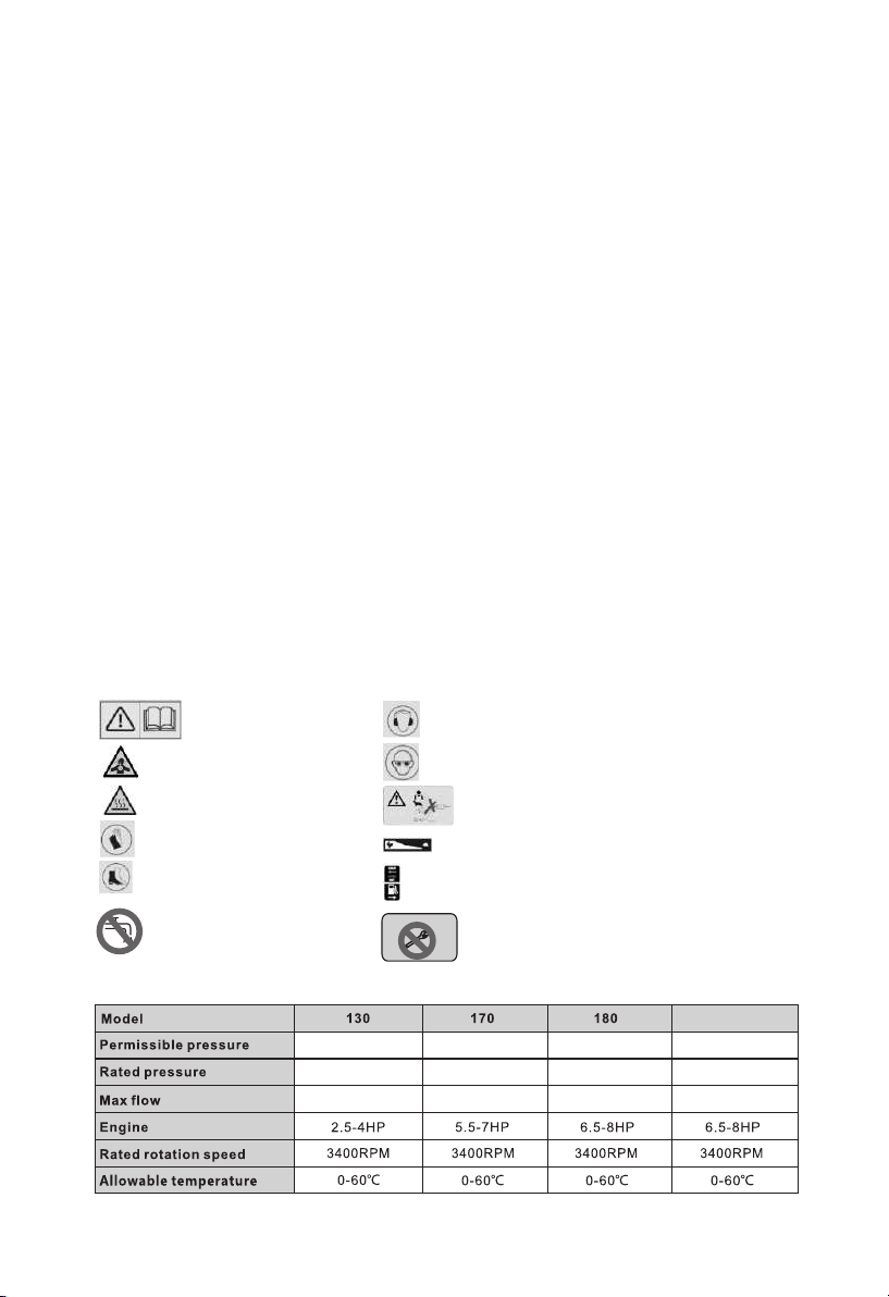
14.5Mpa 19Mpa 20Mpa 17Mpa
11-13Mpa 15-17Mpa 16-18Mpa 13.5-15Mpa
6.5 L/min 9 L/min 9 L/min 12.6 L/min
■Read instructions carefully before operating this product.
■Keep bystanders away.
■This product is for outdoor use only.
■Ensure the engine is stopped before carrying out adjustments,
cleaning or maintenance.
■ Always turn off the engine and water supply when finished.
■Do not use the product if found to be damaged.
■Only use with detergents specified by the manufacturer. Other chemicals may compromise the safety
of the product.
■Do not direct the pressure jet towards mechanical parts containing lubricant grease.
■Clean vehicle tyres from a minimum of 50cm to avoid damage by the high pressure jet.
■Do not point high pressure jets at people, animals, live electrical parts or the product itself.
■Do not use accessories such as hoses and connections that are not advised by the manufacturer.
■Engage the high pressure safety catch located on the gun when not in use.
■Do not step/stand on the high pressure hose.
■Ensure the nozzle is securely attached before using the Product. High pressure can cause it to be fired
from the lance with considerable force, and could cause injury damage.
■Be ready for the kick-back force and the sudden torque on the spray assembly when operating the trigger.
■ A high pressure jet can remove paint and other surface finish. It can also damage tarmac and grouting.
■Switch off completely when not attended.
■The hose is designed specifically for operation with high pressures. Take care to avoid damage that may
prevent correct operation of the product.
■This product is not to be used by children or anyone with reduced capabilities.
■ Always completely unwind the high pressure hose prior to operation.
■Make sure that the machine is switched off before unwinding the high pressure hose, and take care not to
pull the machine over.
■Do not let the high pressure hose contact the hot engine exhaust.
■Do not use this product indoors.
■Keep exhaust emissions away from air intakes.
GENERAL SAFETY INSTRUCTIONS
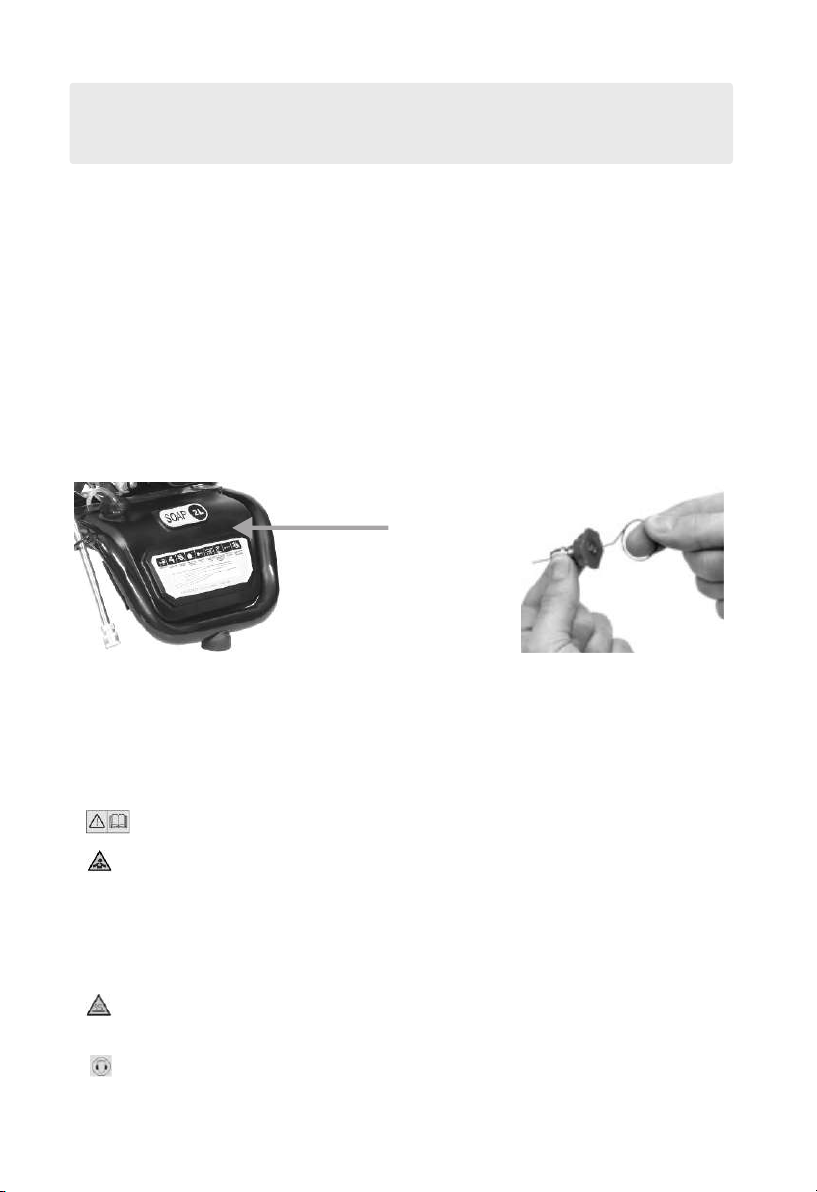
Explanation of the symbols on the appliance!
Warning! Read the operating
instructions before use!
Warning! Do not inhale exhaust fumes!
Attention! Hot surfaces! Risk of burns!
Wear protective gloves!
Wear safety shoes!
Wear hearing protection!
Wear safety goggles!
High-pressure jets can be dangerous if misused. Do not aim at people,
animals, active electrical equipment or at the appliance itself .
Regulate engine speed!
Choke:open/close,petrol:on/off
Machine not suitable for connection to
the potable water mains
Forbidden to adjust
Forbidden to adjust pressure valve
-1-
TECHNICAL PARAMETERS:

■Do not attempt to modify the product in any way.
■To ensure good operating condition arrange regular servicing from an authorising agent.
■Only use replacement parts supplied by the manufacturer
■Only use fresh,clean and good quality fuel in the engine.
■Never operate the engine without oil.
■Never refuel in close proximity to naked flames, sparks or other sources of ignition e.g. cigarettes.
■Do not refuel when the engine is hot.
■Wipe up and correctly dispose of any fuel spillage immediately with a suitable medium.
■Move away from the refuelling areas before restarting the engine. Store fuel for short periods
only in a suitable container away from heat and direct sunlight.
■Clean the pressure washer thoroughly after each use.
■Regularly check external nuts and fixings to ensure vibration caused by normal use has not begun
loosen them. Remove the spark plug ignition lead from the back of the spark plug and position the
lead to avoid accidental reconnection.
■Store the machine in a secure dry location out of reach of children.
■Empty the fuel tank before storage.
MAINTENANCE AND STORAGE
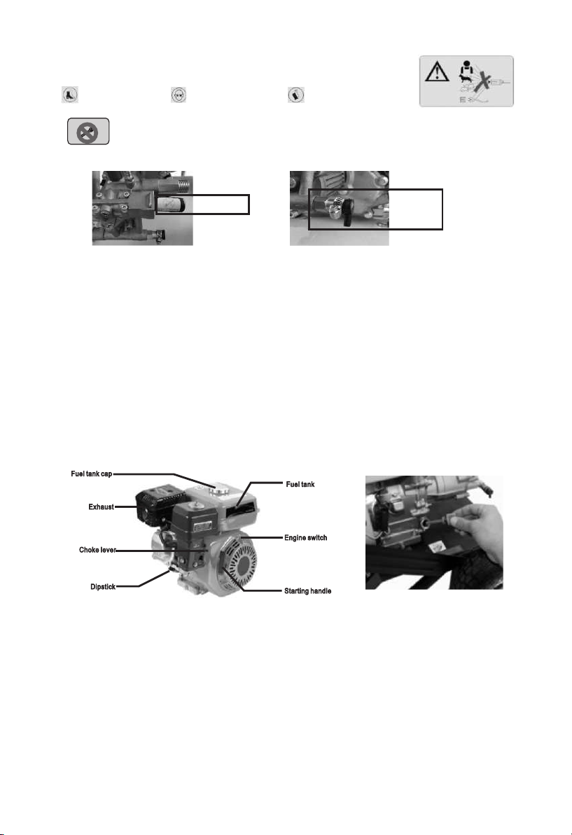
GETTING TO KNOW YOUR PETROL PRESSURE WASHER
1.Engine 2.Pump 3.Lower frame
4.Hand 5.Panel 6.Wheel
7.Lance 8.Hand spray gun 9.Nozzle
10.Hose 11.Soap tank
2
3
5
6
9
10
1
4
7
8
11
-2-
-3-
FIG. 2
ASSEMBLY
FIG. 3
NOTE: Every machine is tested during production,
so there may a few drops of water inside the pump assembly.
FIG. 4
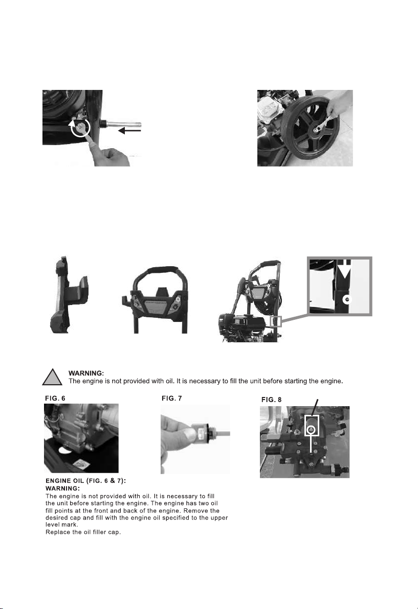
TO ASSEMBLE THE WHEELS
(Figs. 1-2):
FIG. 1
FIG. 5
Insert the axle into the axle tube at
the bottom of the frame, then fix it
with M6 screws.
Assemble the wheel on the axle
and fix it with a nut.
A
Install the hook
for hose
Install the panel on
the upper frame Press the Lock A, install the upper frame
into lower frame
!
PUMP (FIG8):
WARNING:
If you buy a machine with
a red breathing plug, be
sure to remove the yellow
plastic from the plug before
using it
red breathing plug
yellow plastic

OPERATION AND USE
WARNING: The engine is not filled with oil. It is necessary to fill the unit before starting the
engine. The engine will not produce a spark unless sufficient oil is inside.
CAUTION: Do not run the engine with high or low oil level as this can cause engine damage.
CAUTION: Only use unleaded gasoline.
CAUTION: Avoid damaging your hose by ensuring it does not touch the hot exhaust during
and after use.
CAUTION: Avoid damaging your pump by ensuring the water supply is clean and free of any
foreign objects.
CAUTION: Inlet water temperature must not exceed 40 C and 20PSI .
CAUTION: Never let the appliance operate for more than 2 minutes with the spray gun in the
closed position.
CAUTION: Never operate the pressure washer with repeated and rapid on and off movements
of the trigger
o
-4-
BC
PUMP (FIG9):
If you buy a machine
without a red breathing
plug, please ignore FIG8
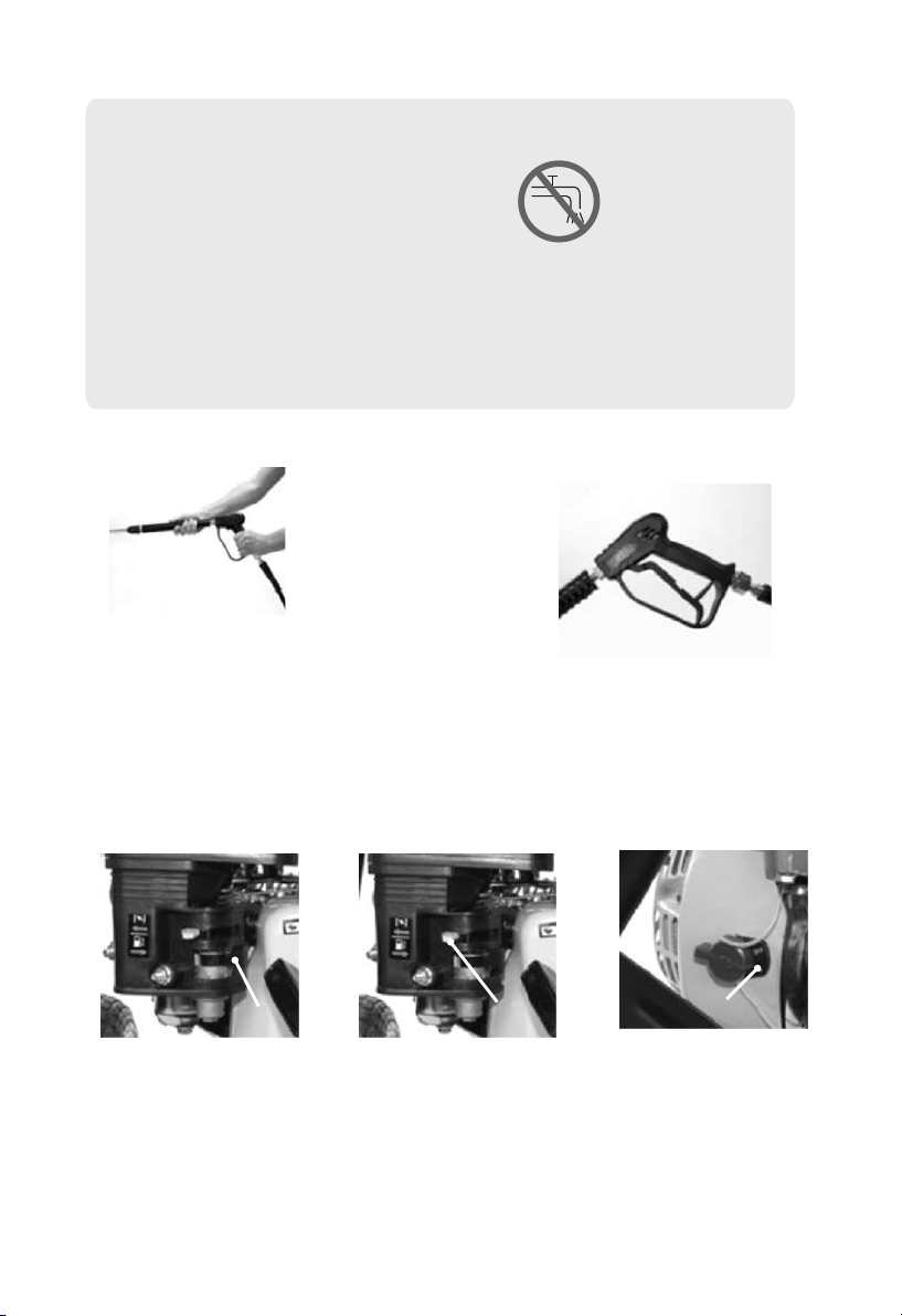
FIG. 14
Pull the trigger to eliminate trapped
air and wait for a steady flow of
water to emerge from the spray nozzle.
NOTE:
In order to assist the first startup it is
recommended to press the trigger
during the pulling of the starter handle.
To prevent accidental operation the
trigger is fitted with a locking facility.
FIG. 15
FIG. 16
STARTING THE ENGINE
(FIG. 16-19):
Push the fuel lever A to the
right (On position).
A
FIG. 18
Turn the engine switch
clockwise to the ON position.
ON
FIG. 17
Push the choke lever B to the
left; closing the choke for initial
start-up.
NOTE: Do not use the choke
if the engine or air tempreture
is warm.
B
WATER SUPPLY FROM THE WATER MAIN
■Connect a water supply hose (not supplied) to the water inlet connection of the pressure washer.
■Turn on the water supply and pull the trigger until water
is continually flowing out of the nozzle.
WATER SUPPLIER FROM A CONTAINER
■Unscrew the coupling part for the water inlet.
■Screw the suction hose with filter (not included) onto the water connection of the unit.
■Hang the filter in the container.
■Vent the unit before operation.
■Unscrew the high pressure line at the high pressure outlet of the unit.
■Switch on the unit and let it run until water is free of bubbles at the high pressure outlet.
■Switch off the unit and screw on the high pressure hose again.
■Machine not suitable for connection to the potable water mains
-5-
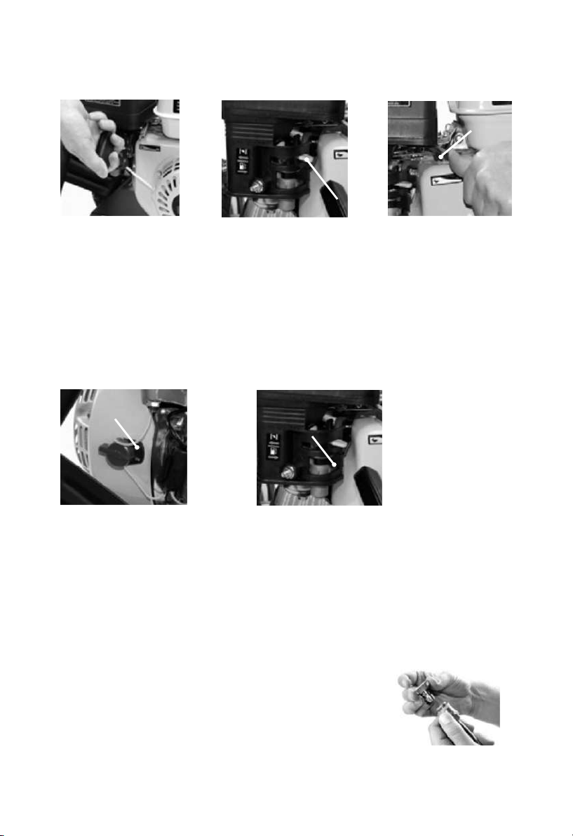
FIG. 23
Turn the engine switch
anticlockwise to the OFF
position. Then slide the fuel
lever E to the right; OFF
position.
CAUTION: When you have
finished working turn off the
engine. When the machine is
switched off, always discharge
the pressure by pressing the
trigger.
E
FIG. 22
STOPPING THE ENGINE
(Fig 22-23):
In an emergency turn the engine switch
anticlockwise to the OFF position to stall
the engine.To stop the appliance normally
use the following sequence.
OFF
FIG. 19
Pull the black starting rope
handle gradually until you
feel resistance; then make a
rapid pull.
NOTE: Return the starting
rope handle gently to prevent
damage to the starter
assembly.
Do not pull the rope all the
way out as this can damage
the starter assembly.
FIG. 20
Let the engine idle for a short
while to preheat before pushing
the choke lever C to the right.
C
FIG. 21
When the appliance is in
operation, the speed can be
adjusted by moving the throttle
D control lever to the high
position (indicated by a hare).
NOTE: There is a stop bracket
on the throttle control lever, do
not force this bracket as it can
damage the engine.
D
ADJUSTING THE SPRAY PATTERN (Fig.24)
You have the choice of 4 different colour coded nozzles giving you different spray patterns to choose from:
0° nozzle (Red):This nozzle delivers a pinpoint stream and is extremely powerful. It covers a very small
area of cleaning. This nozzle should only be used on surface that can withstand this high pressure such as
metal or concrete. Do not use on wood.
15°nozzle (Yellow):This nozzle delivers a powerful 5 degree spray pattern for
intense cleaning of small areas. This nozzle should only be used on areas that
can withstand the high pressure from this nozzle.
40°nozzle (White):This nozzle delivers a 40 degree spray pattern and a less
powerful stream of water. It covers a wide area of cleaning. This nozzle should
be used for most general cleaning jobs.
Low pressure nozzle (Black): This nozzle is used to apply chemicals or
cleaning solutions. It has the least power stream.
FIG. 24
-6-
NOTE:
Before using the pressure washer to clean patio paving slabs it is advisable to test a small area first,
some paving slabs are manufactured from inferior materials and the use of a pressure washer could
damage the surface.
USING THE DETERGENT FACILITY (Fig. 25)
Fill a suitable container with pressure water detergent. Do not use washing up liquid as it contains salt. We
recommend the use of good quality pressure washer detergent for use with this pressure washer. Most
automobile detergents are a combination of a detergent and a wax solution. The viscosity (thickness) of the
detergent will increase in cold weather. It is recommended that this type of detergent is diluted with water before
filling the container. When using combination wash and wax solutions we recommend that they are diluted before
use. As a general guide we would recommend a dilution rate of 50/50. However a trial and error process would
determine the ideal dilution rate for a particular detergent.
NOTES:
A thick viscous detergent would not flow freely from the detergent tank and the residue would cause a blockage
flow system. After using the detergent facility it should be flushed thoroughly using copious amount of water. To
activate detergent delivery, fit the Black LOW PRESSURE nozzle to the and of the lance. Submerge the and of
the detergent pick up pipe into your container of pressure water detergent. Suction and mixing will occur
automatically as the water flows though the pump.
FIG. 25 FIG. 26
CLEARING A BLOCKAGE (Fig. 26)
If at any time the flow rate stutters or is inconsistent, release the trigger and switch OFF the machine.
Squeeze the trigger to relieve any pressure and check the jet in the end of the lance for any blockage.
If a blockage is suspected use some wire to clean the inside of the nozzle.
SAFETY INSTRUCTIONS FOR THE WASHER
1. Before operating the engine, be sure to read all instructions carefully as injury or permanent damage to
equipment may occur.
2. Run the engine in a well ventilated area.
3.Ensure the appliance is at least one metre away from building walls or other equipment.
4. keep the appliance away from flammable liquids such as petrol.
5.Refuel in a well ventilated area with the engine switched off and avoid sparks or naked flames.
6.When refuelling ensure that you do not overfill the fuel tank.
7.If any fuel is spilled ensure it is deaned up thoroughly before restarting.
8.Ensure the fuel cap Is located securely.
9.
10.Ensure the appliance is cooled before transporting or storing.
11.
wear ear protection to prevent hearing damage!
Not to be used in explosive environment,
The exhaust mufflers, engine case, pump get very hot and will remain hot for sometime after the engine
is switched off.
Sound pressure level:94dB; Sound power level:109dB.
Soap tank
-7-
PRE-OPERATION INSPECTION
CAUTION: Do not use
with additives or 2-stroke gasoline engine oil, as they do not have enough lubricating properties,
which may shorten the engine’s service life.
1 Check the engine is on level ground.
2. 0.6L 15W-30 is recommended for general all temperature use. (FIG. 27)
3.Remove the dipstick and clean it.
4.Reinsert the dipstick into the oil filler without screwing it in and check the oil level.
5.If the oil level is too low add the required amount of engine oil to the oil filler mark.
6.Replace the dipstick securely.
CAUTION: Running with insufficient engine oil may damage the engine severely.
Engine oil is a key factor in deciding the engine’s performance. engine oil
.
FIG. 27
12.High-pressure jets can be dangerous if misused. Do not aim at people, animals,
active electrical equipment or at the appliance itself .
Wear safety shoes! Wear safety goggles! Wear protective gloves!
13.
Forbidden to adjust pressure valve, Otherwise it will cause pump damage。
14. 60 degrees hot water will be ejected from thermal relief valve before water gun closed for
about 1 minute. Careful burns。
pressure valve Thermal
relief valve
15. WARNING Do not use the machine within range of persons unless they wear protective clothing.
16. WARNING Do not direct the jet against yourself or others in order to clean clothes or foot-wear
17. WARNING Risk of explosion – Do not spray flammable liquids.
18. WARNING High pressure hoses, fittings and couplings are important for the safety of the machine.
Use only hoses, fittings and couplings recommended by the nufacturer.
19. WARNING To ensure machine safety, use only original spare parts from the manufacturer or approved
by the manufacturer.
20. WARNING Water that has flowed through backflow preventers is considered to be nonpotable.
Forbi dd en to a dj ust
-8-

FUEL AND FUEL TANK:
Only use unleaded petrol or fuel with an octane number over 86. Using unleaded petrol or fuel will decrease the
possibility of producing carbon deposit and prolong the engines service life. Never use old or polluted petrol or
fuel or a mixture of petrol and engine oil. Make sure the fuel is free of dirt and water.
CAUTION:
Handle fuel with care because it can damage plastic and painted surfaces.Remove the fuel filler cap and check
the fuel level. If the fuel lever is too low, refuel the tank. Remember when adding fuel do not fill over the fuel
filter shoulder.
WARNING:
Petrol is extremely flammable and is explosive under certain conditions. Refuel in a well ventilated area with the
engine stopped. Do not smoke or allow flames and sparks in the area where petrol is stored or where the fuel
tank is refuelled. After refuelling make sure the fuel cap is returned securely.Be careful not to spill fuel when
refuelling. Spilled fuel or fuel vapour may ignite. If any fuel is spilled make sure the area is dry before starting
the engine.
FUEL TANK FILTER (Fig.28):
After every 150 hours of running or every three months the fuel tank filter should be removed and cleaned.
Remove the fuel tank filler cap and the filter, clean the filter thoroughly using environmentally friendly water
based degreasing agent and re-fit.
OIL LEVEL SWITCH:
The engine oil alarm is designed to prevent the operator starting the engine when the oil in the crankcase is
insufficient. Running with insufficient oil will damage the engine. Once the oil level in the crankcase is too
low, the engine oil alarm will stall the engine automatically to avoid damage while the engine switch is still ON.
FIG. 28
AIR FILTER (Fig.29):
After every 100 hours of running or every month, the air filter should be removed and examined for deterioration
and cleaned. Clean the air filter thoroughly using environmentally friendly water based degreasing agent. Allow
to dry fully then replace the air filter. Never run the engine without the air filter fitted.
STORAGE:
If the engine is not to be used or is to be stored for more than one month the following storage procedure should
be carried out.
1. Drain all the fuel from the fuel tank and the carburettor ensure that all the fuel has been removed.
2.Remove the spark plug and pour approximately one tablespoon full of clean engine oil into the spark plug hole.
3.With the ignition turned OFF gently pull on the recoil starter cord several times.
4.Re-fit the spark plug and continue to pull the recoil starter cord until the piston is on the compression stroke
(when resistance is felt) then stop pulling.
5.Store the pressure washer in a dry well ventilated place under a cover to prevent any dust or debris from
accumulating on the pressure washer.
WINTER AND LONG TERM STORAGE:
If the pressure washer is not to be used for more than 3 months or if there is a danger of ice or frost during winter
months the pump unit will require protection to prevent seizing and damage caused by freezing.
FIG. 29
-9-

MAINTENANCE
EXHAUST CONTROL SYSTEM
With the engine running, carbon monoxide, nitrogen oxide and hydrocarbon are produced, and in certain
conditions nitrogen oxide and hydrocarbon will react together to make smoke while carbon monoxide is toxic,
so exhaust control is very important. The manufacturer decreases exhaust emissions by introducing poor-fuel
carburettors and other devices to solve the problem. To keep the exhaust of your engine within the standard
exhaust emission values, pay attention to the following:
MAINTENANCE
Maintain the engine periodically in accordance with the maintenance schedule. The maintenance schedule is
made out on the basis of normal use in normal conditions. If using under heavy load, dusty or wet conditions
or in high temperature, more frequent maintenance will be necessary.
REPLACEMENT OF PARTS
We recommend that you use parts that are supplied by the manufacturer or equivalent quality parts.
Replacement parts of inferior quality may impair the effectiveness of the exhaust control system.
MODIFYING
Modifying the exhaust control system may make exhaust emissions exceed statutory limits. Illegal
modifications are:
Dismantling or modifying any part of the air inlet or outlet system.
Modifying or removing speed adjustment controls or connections which may result in the engine running
outside its set parameters.
PROBLEMS AFFECTING EXHAUST EMISSIONS
1.Difficulty in starting or stopping.
Erratic idling.
Poor ignition spark or no spark.
5.Ignition too advanced. If you have any of these above problems please contact your dealer.
CAUTION:
Before carrying out any maintenance to the machine release any
pressure and remove the water connection.
WATER SUCTION FILTER CHECKING
Check periodically in order to avoid deposits clogging it.
1.
2.
2.
3.
4.
Giving off black smoke or excessive fuel consumption.
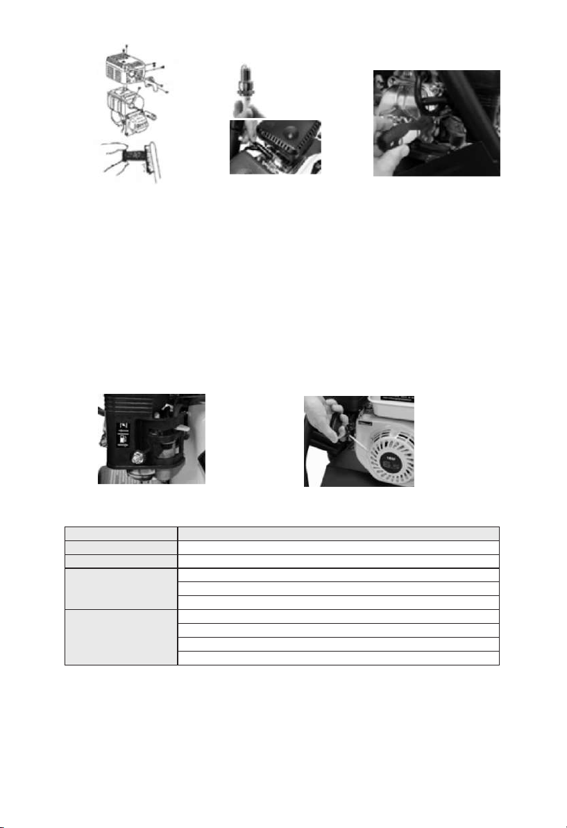
SPARK PLUG MAINTENANCE
After every 50 hours clean the spark plug with a brush. If the insulator on the spark plug is damaged replace
it immediately. Check the spark plug gap with a feeler gauge, the gap should be 0.7 - 0.8mm. If adjustment is
necessary bend the side electrode carefully. Check the spark plug gasket is in good condition or replace with
a new one. Screw in the spark plug to the bottom first by hand and then tighten by using a spark plug wrench.
If a new spark plug is used, twist a 1/2 more turn after impacting the gasket. If using the original one twist
1/8 -1/4 more turn.
CAUTION:
The spark plug eliminator should be serviced at least once every 100 hours of operation so as to keep it in
good condition.
WARNING:
The muffler is very hot during running the engine and for a prolonged period after stopping. Only service after
the engine cools down completely.
Unscrew two nuts and remove the exhaust elbow from the engine body.
Unscrew five screws from the muffler guard and take it out.
Unscrew from the spark plug eliminator and separate from the muffler.
Clean the spark eliminator mesh with a wire brush.
Reinstall the spark eliminator in reverse order of removal.
CAUTION:
Be careful not to damage the spark eliminator. Never use a damaged spark eliminator.
CARBURETTOR IDLING ADJUSTMENT:
Start and pre-heat the engine until it reaches normal working temperature. Obtain standard idling by adjusting
the throttle fixing screw under the engine, Standard idling: 3400 300rpm.
+
_
-10-
TRANSPORT
Transport with the fuel switch in the off position. Ensure the engine is cooled so as to avoid the risk of
burns or fire.
CAUTION:
Do not tilt the engine to avoid spilling fuel. Spilled fuel or fuel vapour may ignite.
STORAGE
If the engine is not to be used for a long period of time ensure it is stored correctly. Make sure the storage
area is dry and free of dust.
PREPARE FOR STORAGE
Disconnect the spark plug. Put a spoonful of fresh engine oil into the cylinder and rotate the engine to
distribute the oil evenly. Replace the spark plug. Pull the starting rope until you feel resistance and then
keep pulling so as to align the arrow of the starting sleeve with the hole of the starter: This will close both
the inlet and outlet valves to help prevent the engine rusting inside.Cover the engine to keep it free of dust.
REMOVAL FROM STORAGE
Before re-using, service the engine in accordance with the instructions in the following table.
1 Unscrew the drain plug and drain out the fuel in the carburettor:
2 Turn off the engine switch first, disconnect the deposit cup and empty it.
NOTE:
Do not dump oil containers or discarded engine oil into the ground. For environmental protection take
discarded engine oil in a closed container to a recycling station.
WARNING:
Fuel is extremely flammable and explosive under certain conditions. Keep cigarettes, naked flames and
sparks away from operating site.
No service needed
Drain out original fuel of the fuel tank and refuel
Drain out original fuel of the fuel tank and refuel
Drain out the fuel in the carburettor 1
Empty the deposit cup 2
Drain out original fuel of the fuel tank and refuel
Drain out the fuel in the carburettor 1
Empty the deposit cup 2
Move the engine from the storage place, and start up
SERVICE ITEM
STORAGE TIME
Within one month
One - Two months
Two months - One year
Above One year
-11-
To keep the engine in sound condition, the user should maintain it according to the table below.
CAUTION:
Use parts that are supplied by the manufacturer, otherwise damage to the engine may occur.
WARNING:
Stop the engine before servicing. If servicing is required with the engine running ensure there is good ventilation
in the area. Exhaust emissions contain toxic carbon monoxide which may cause injury or be fatal if inhaled.
ENGINE OIL REPLACEMENT
Place the machine on a level surface and warm up the engine for several minutes. Then stop the engine.
Remove the oil filler cap
Place an oil pan under the engine. Remove the oil drain plug so that the oil can be completely drained. You will
need to use a tube or other similar device to prevent the oil leaking onto the frame of the pressure washer.
Check the oil drain plug, gasket oil filler cap and O-ring and if damaged replace.
Reinstall the oil drain plug.
Add engine oil up to the upper level of the dipstick.
NOTE:
Do not dump oil containers or discard engine oil into rubbish boxes or into the ground. For environmental
protection take discarded engine oil in a closed container to a recycling station.
*
**Only for paper core air cleaners.
Only for inside ventilating double-core carburettors.
1.More often than in schedule if used in dusty conditions
2.Items to be done by dealer unless you are fully trained and equipped to do so.
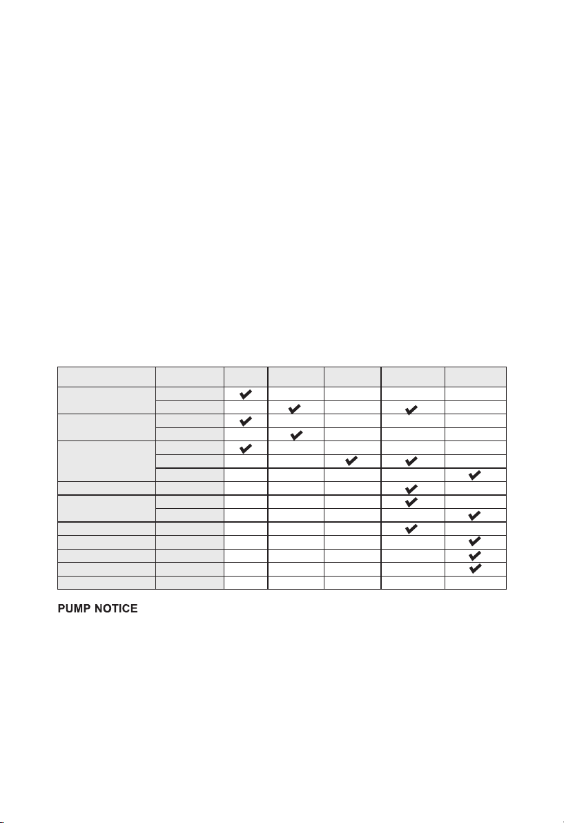
NOTES:
Item
Engine oil Oil level check
Replace
Reduction gear oil Oil level check
Replace
Air cleaner
Check
Clean
Replace
Deposit cup Clean
Spark plug Clean, adjust
Replace
Spark eliminator Clean
Idling Clean, adjust
Valve clearance Clean, adjust
Fuel tank & fuel filter Clean
Fuel supply line Check
Each time First month
or 20 hours
Each month
or 50 hours
Each 6 months
or 100 hours
Each year or
300 hours
11*
**
2
2
2
-12-
Following operations and maintenance will extend the service life of the pump:
1.After using 20 hours of the new machine, pour out the machine oil,
and add the appropriate amount of kerosene.
Operate the pump without load in 10-15 seconds,
then close the machine and pour out the kerosene, finally add the new oil.
2.Accumulative use after 100 hours,
change the oil in the same way like above.

TROUBLESHOOTING
PUMP TROUBLESHOOTING
TROUBLE PROBABLE CAUSE REMEDY
Fluctuating pressure
Pump sucking in air
Valves dirty, worn out or seized
Blocked jet
Check connection are tight
Contact customer helpline
Remove blockage using jet cleaning tool
Water leakage from pump Seals worn out Contact customer helpline
The pump does not reach the
required pressure
Pump sucking in air from
connections or hose
Check tightness of all connections
Suction/delivery valves are
clogged
Clear or replace valves.
Have machine checked by Service Centre
Unload valves are stuck Loosen and re-tighten regulating screw
Lance or nozzle worn out Check and/or replace
Pump is running but no water
delivery
Kinked inlet and or pressure hose
Blocked inlet filter
Blocked jet
Check, straighten and replace if required
Remove and clean filter
Remove blockage using the jet cleaning tool
ENGINE TROUBLESHOOTING
REPAIR
Tighten plug
Tighten bolt
Replace gasket
Pull rope sharply
Insufficient pulling speed for
starting rope
Clean tank
Clean fuel line with dealers advice
Supply fuel
Open tap
Remove carbon or dry spark plug
Spark plug dirty with
carbon or wet with fuel
Replace spark plug
Consult dealer
Faulty magneto
Pull rope sharply
Insufficient pulling
speed for starting rope
Check grade of fuel
Check the working conditions
Overheating
Overloaded
Wrong grade of fuel used
Improper adjustment of
carburetor
Damaged spark plug
Fuel tap not open
No fuel in tank
Clogged fuel line
Foreign matter in fuel tank
PROBABLE CAUSE
Loose spark plug
Loose cylinder head bolt
Damaged gasket
FUEL SYSTEM PROBLEMS
FUEL SYSTEM PROBLEMS
Poor
spark
Good
spark
Combustion
chamber
supplied with
fuel
No fuel
supplied to
combustion
chamber
Insufficient
compression
Sufficient
compression
Engine
won’t start
Low
engine
output
Engine
runs
erratically
FAULT
-13-

-14-

Other manuals for 130
3
This manual suits for next models
3
Table of contents
Other Bison Pressure Washer manuals


Popular Pressure Washer manuals by other brands


Kärcher
Kärcher K 2.97 M manual

Krüger Technology
Krüger Technology KHL120F instructions

EUROM
EUROM Force 1200 instruction manual

Powr-Flite
Powr-Flite PF1200RT Operator's manual & parts list

DeVilbiss Air Power Company
DeVilbiss Air Power Company MPG-1217 owner's manual

VITO
VITO PRO-POWER POWERWASH 150 HQ instruction manual