DB-200-5 7
Extreme pressure pulsations should be damped by fit-
ting pulsation mufflers.
4.4 Refrigerant / oil side
The whole system should be designed and operated in
order to guarantee that the maximum operating pres-
sure in the pressure vessel cannot be exceeded.
Pressure relief valves are essential if
• it is to be expected that the maximum operating
pressure will be exceeded due to external heat
sources (e.g. fire), or if
• the entire refrigerant charge of the plant is more than
90% of the receiver volume at 20°C (charge capa-
city). Receiver volume means the volume between
operationally lockable valves before and after a pres-
sure vessel. In case of two vessels being mounted in
series, it is the volume of both vessels and the con-
necting pipe.
In these cases relief devices should be installed that
lead the refrigerant or the oil to the low-pressure side of
the plant (emission reduction).
Safety switching device
According to the local regulations, safety switching
devices for pressure limiting must be provided.
4.5 Coolant side
The coolant should contain neither solids nor gases:
• Any solids must be separated out using suitable fil-
ters.
• The presence of gas should be avoided through suit-
able design measures.
Open circuits: The pressure vessel must not drain off
while not in use. For this reason, fit either
• a coolant regulator at the coolant outlet of the pres-
sure vessel, or
• a swan-neck at the outlet.
When using tap-water as a coolant, it is necessary to
check whether the installation of a pipe disconnector is
stipulated.
When cooling with seawater: If, due to local conditions,
the seawater in use can lead to scale or shell deposits,
suitable filters should be fitted. This also serves to pro-
tect the pipe lines from shell deposits.
4.6 Delivery condition
The pressure vessel is sealed in the delivery condition
and filled with inert gas. The inert gas overpressure is
0.2 .. 0.5 bar. All Rotalock and flange connections are
closed by blanking plates. These plates must be re-
moved before commissioning.
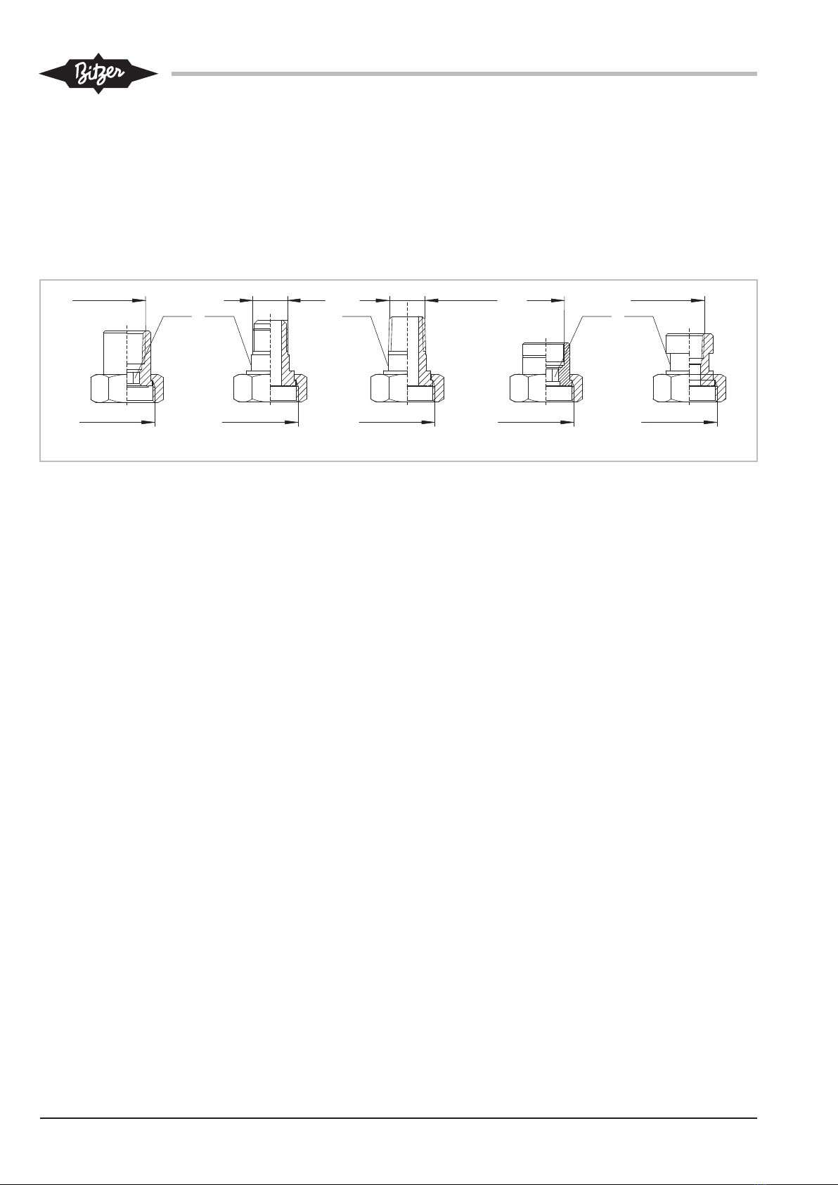
4.7 Connecting the pipelines
The pipe connections are suitable for pipes in all com-
mon dimensions in millimetres and inches. Brazed con-
nections have stepped diameters. The pipe will im-
merge more or less depending on its dimensions. If not
required the end with the largest diameter can be cut-
off.
DANGER
Risk of bursting the pressure device due to
mechanical stress.
Serious injuries are possible.
Connect the pipeline to the pressure unit without
stress!
First relieve the excess pressure from the pressure
vessel: Open the connections carefully.
WARNING
The pressure equipment is under pressure!
Serious injuries are possible!
Depressurise the pressure equipment!
Wear safety goggles!
Remove shut-off valves and/or solder connections.
NOTICE
Potential chemical reactions due to air penetra-
tion!
Install the open pressure vessel immediately in
the system.
Reseal the pressure vessel during installation breaks.
NOTICE
Do not overheat the shut-off valves!
Cool the valve body during and after the brazing
operation.
Maximum brazing temperature 700°C!
When brazing or welding, rinse the corresponding con-
ductive parts with inert gas.