6
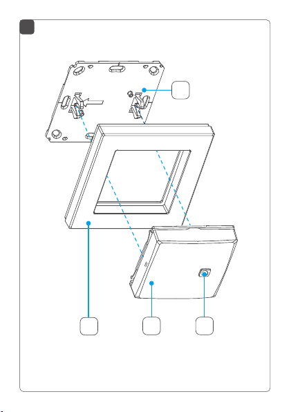
Package contents
Quantity Description
1 Daikin Home Controls Room Sensor
1 Clip-on frame
1 Mounting plate
2 Double-sided adhesive strips
2 Screws 3.0 x 30 mm
2 Plugs 5 mm
2 1.5 V LR03/micro/AAA batteries
1 Installation and operation manual
Documentation © 2022 Daikin Europe N.V., Belgium.
All rights reserved. This manual may not be reproduced in any
format, either in whole or in part, nor may it be duplicated or edited
by electronic, mechanical or chemical means, without the written
consent of the publisher.
Typographical and printing errors cannot be excluded. However,
the information contained in this manual is reviewed on a regular
basis and any necessary corrections will be implemented in the next
edition. We accept no liability for technical or typographical errors or
the consequences thereof.
All trademarks and industrial property rights are acknowledged.
Printed in Hong Kong.
Changes may be made without prior notice as a result of technical
advances.
4P687368-1
2022.04
Table of contents
1 Information about this manual.................................. 8
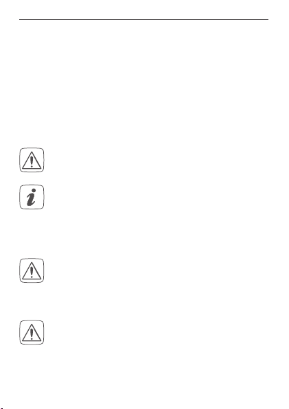
2 Hazard information................................................... 8
3 Daikin Home Controls ............................................ 10
4 Function and accessory overview .......................... 11
5 Start-up................................................................... 12
5.1 Connecting to the DHC Access Point.......................... 12
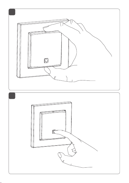
5.2 Mounting ..................................................................... 13
5.2.1 Adhesive strip mounting .................................. 13
5.2.2 Screw mounting............................................... 14
5.2.3 Flush-mounted box mounting .......................... 15
6 Replacing batteries................................................. 17
7 Troubleshooting...................................................... 18
7.1 Weak battery ............................................................... 18
7.2 Duty cycle ................................................................... 19
7.3 Errorcodesandashingsequences........................... 20
8 Restore factory settings.......................................... 22
9 Maintenance and cleaning ..................................... 23
10 General information about radio operation............. 24
11 Technicalspecications.......................................... 25