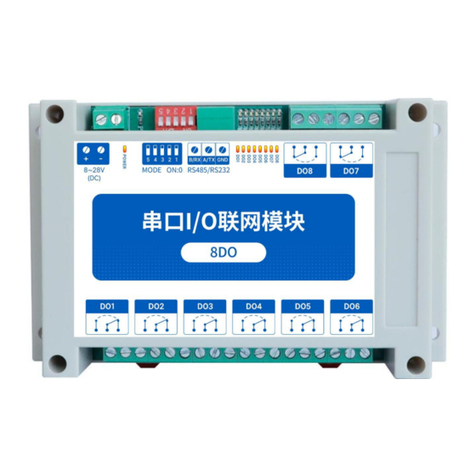
Ebyte MA02-XXCX0080 User manual

Chengdu Ebyte Electronic Technology Co.,Ltd. 【8DO】MA02-XXCX0080 User Manual
Copyright ©2012–2021,Chengdu Ebyte Electronic Technology Co.,Ltd.
第1页
【8DO】
MA02-XXCX0080

Chengdu Ebyte Electronic Technology Co.,Ltd. 【8DO】MA02-XXCX0080 User Manual
Copyright ©2012–2021,Chengdu Ebyte Electronic Technology Co.,Ltd.
第2页
Contents
1、Product profile..................................................................................................................................4
2、Quick entry.......................................................................................................................................5
2.1 Use preparation........................................................................................................................ 5
2.2Equipment wiring......................................................................................................................5
2.2.1Power supply wiring.......................................................................................................5
2.2.2 Communication wiringRS232........................................................................................ 6
2.2.3 Overall wiring schematic diagram................................................................................ 6
2.3 Software settings...................................................................................................................... 8
2.3.1 Device attachment...................................................................................................... 8
2.3.2 Equipment testing..........................................................................................................9
3、Product Overview.........................................................................................................................10
3.1 Specifications of the products................................................................................................ 10
3.2 Technical parameters........................................................................................................... 11
3.3 Port Description......................................................................................................................12
3.4 Dimensional drawing............................................................................................................. 13
3.5 Way to install.......................................................................................................................13
4、Product function............................................................................................................................. 14
4.1 Switched output DO............................................................................................................ 14
4.1.1Switched output DO illustrate...................................................................................... 14
4.1.2 Switch output DO mode settings.................................................................................14
4.2 Unit address............................................................................................................................15
4.2.1 unit address..................................................................................................................15
4.2.2 Hardware address (code dial switch).......................................................................... 15
4.2.3 Software address (offset address)................................................................................17
5、Port connection...............................................................................................................................17
5.1 Switch output DO port wiring................................................................................................17
5.1.1 The output terminal has direct control load (small power equipment within 1kW)... 17
5.2.2 Output Control Contactor (Contactor Control high power 220V equipment)............ 18
5.2.3 Output controls the contactor(Contactor control high power 380V equipment)......18
6、Software use................................................................................................................................... 19
6.1 Software use........................................................................................................................... 19
6.2 Introduction of software function...........................................................................................20
6.2.1 IODemo interface........................................................................................................20
6.2.2 Basic Setup Interface...................................................................................................23
6.2.3 Advanced Setup Interface............................................................................................24
6.3 Device status query................................................................................................................ 25
6.4 Device status control.............................................................................................................. 27
7、The Modbus is used in the..............................................................................................................29
7.1 List of registers.......................................................................................................................29
7.2 Directive Format (Part).......................................................................................................... 30
7.2.1 Read the DO output coil status....................................................................................30
7.2.2 Read to keep the register............................................................................................. 30
Chengdu Ebyte Electronic Technology Co.,Ltd. 【8DO】MA02-XXCX0080 User Manual
Copyright ©2012–2021,Chengdu Ebyte Electronic Technology Co.,Ltd.
第3页
7.2.3 Write a single hold register.......................................................................................31
7.2.4 Write about multiple hold registers............................................................................. 31
7.2.5 Write a single DO coil state.........................................................................................32
7.2.6 Write about the multiple DO coil states...................................................................... 32
Revisionhistory..................................................................................................................................... 33
Aboutus................................................................................................................................................ 33

Chengdu Ebyte Electronic Technology Co.,Ltd. 【8DO】MA02-XXCX0080 User Manual
Copyright ©2012–2021,Chengdu Ebyte Electronic Technology Co.,Ltd.
第4页
1、Product profile
MA02-XXCX0080 Support for configuration software or PLC,Control the 8-way relay switch
output (DO) via a serial port (RS232) issuing command,Serial port I/O networking module for
implementing remote control function(“ long-range IO”).
Features special
Modbus RTU protocol;
Support all kinds of configuration software / PLC/ touchscreen;
RS232 control IO;
DC 8~28V for power supply;
8 Road switch output DO(relay);
Switch output (DO) supports level mode, pulse mode;
Communication Potter rate 1200~115200(Default 9600),Support for custom settings;
Supports 1~247 From Station,The 5-bit dialing switch can set a 1~31 address code,More than
31 may be set up by the software.

Chengdu Ebyte Electronic Technology Co.,Ltd. 【8DO】MA02-XXCX0080 User Manual
Copyright ©2012–2021,Chengdu Ebyte Electronic Technology Co.,Ltd.
第5页
2、Quick entry
If there is a problem during the use process, click on the official website link :
https://www.ebyte.com/product-class.aspx
2.1 Use preparation
Serial port I/O networked devices (hereinafter referred to as "IO devices") before use,Computer,
converter, power supply, screwdriver and other related auxiliary materials should be prepared.The
details are as follows:
Table 2-1-1 Preparation list
Serial
number
Serial number
Serial number
Devices
Devices
Devices
Number
Number
Number
1
1
1
IO device
IO device
IO device
1
1
1
2
2
2
USB
turn-serial
port
converter
USB turn-serial port converter
USB turn-serial port
converter
2.2Equipment wiring
2.2.1Power supply wiring
Power supply, with either a DC 8~28V or a DC 12V or 24V power supply.

Chengdu Ebyte Electronic Technology Co.,Ltd. 【8DO】MA02-XXCX0080 User Manual
Copyright ©2012–2021,Chengdu Ebyte Electronic Technology Co.,Ltd.
第6页
Fig 2-2-1 Power supply wiring diagram
2.2.2 Communication wiringRS232
Fig 2-2-2 Communication RS232 wiring diagram
2.2.3 Overall wiring schematic diagram
(1)After electric on equipment,Power light (POWER)Often bright,Equipment power supply
is normal.
(2)Analog input AI wiring,As showConnect the signal generator to the analog input AI port.
(3)Switch Output the DO wiring,As show connect the load to the switch to output DO port.

Chengdu Ebyte Electronic Technology Co.,Ltd. 【8DO】MA02-XXCX0080 User Manual
Copyright ©2012–2021,Chengdu Ebyte Electronic Technology Co.,Ltd.
第7页
Fig 2-2-3 Overall wiring schematic diagram

Chengdu Ebyte Electronic Technology Co.,Ltd. 【8DO】MA02-XXCX0080 User Manual
Copyright ©2012–2021,Chengdu Ebyte Electronic Technology Co.,Ltd.
第8页
2.3 Software settings
2.3.1 Device attachment
Fig 2-3-1 The software interface
[spend] operating steps :
(1)Open the serial port,Find the corresponding device port number,The Potter rate is
default9600,Click "Open serial ial".
Fig 2-3-2 Open the serial port
(2)In the device window,Click "Search Device",The right log window begins to refresh
the search information.After the equipment column in the equipment window displays the
connected device,Click on the Stop Search " menu.Click the device again, and the connection is
successful.

Chengdu Ebyte Electronic Technology Co.,Ltd. 【8DO】MA02-XXCX0080 User Manual
Copyright ©2012–2021,Chengdu Ebyte Electronic Technology Co.,Ltd.
第9页
Fig 2-3-3 Connect the device
2.3.2 Equipment testing
Fig 2-3-4 Equipment testing
Fig 2-3-5 Actual test effect

Chengdu Ebyte Electronic Technology Co.,Ltd. 【8DO】MA02-XXCX0080 User Manual
Copyright ©2012–2021,Chengdu Ebyte Electronic Technology Co.,Ltd.
第10 页
3、Product Overview
3.1 Specifications of the products
List 3-1-1 specifications of the products
product model
specification
s
SwitchQua
ntity
inputDI
read
analogue
input AI
SwitchVolum
e outputDO
RS485
RS232
MA01-AXCX4020
4DI+2DO
4Road
—
2Road
●
×
MA02-AXCX4020
4Road
—
2Road
×
●
MA01-XACX0420
4AI+2DO
—
4Road
2Road
●
×
MA02-XACX0420
—
4Road
2Road
×
●
MA01-AACX2220
2DI+2AI+2D
O
2Road
2Road
2Road
●
×
MA02-AACX2220
2Road
2Road
2Road
×
●
MA01-AXCX4040
4DI+4DO
4Road
—
4Road
●
×
MA02-AXCX4040
4Road
—
4Road
×
●
MA01-XACX0440
4AI+4DO
—
4Road
4Road
●
×
MA02-XACX0440
—
4Road
4Road
×
●
MA01-AACX2240
2DI+2AI+4D
O
2Road
2Road
4Road
●
×
MA02-AACX2240
2Road
2Road
4Road
×
●
MA01-XXCX0080
8DO
—
—
8Road
●
×
MA02-XXCX0080
—
—
8Road
×
●

Chengdu Ebyte Electronic Technology Co.,Ltd. 【8DO】MA02-XXCX0080 User Manual
Copyright ©2012–2021,Chengdu Ebyte Electronic Technology Co.,Ltd.
第11 页
3.2 Technical parameters
Tables 3-2-1 technical parameters
Category
Name
Parameter
Power
Supply Voltage
Direct-current (DC)8~28V
working current
50mA @12V
Power supply
indicators
Green LED indicates
Serial Port
communication
interface
RS232
Baud rate
1200~115200 bps(默认 9600 bps)
Data bit
8(Regular)
Check bit
No calibration, odd, parity (none by default)
Stop bit
1(Fixed)
Protocol
Modbus RTU Protocol
Unit Address
1~247(Default address: 1)
DO Output
DO Way
8 Road
DO Output type
Type C relay (often open + often closed)
DO Output mode
Level mode, pulse mode
Relay contact capacity
30V/10A、250V/10A
Output instructions
Red LED indicates
Other
Product size
145 mm * 90 mm * 40mm (Long * width * height)
Product weight
250g ± 5g
Work
temperature&humidity
-40 ~+85℃、5%~95%RH(No clotting)
Storage
temperature&humidity
-60 ~+125℃、5%~95%RH(No clotting)
way to install
Installation of positioning hole and guide rail
installation

Chengdu Ebyte Electronic Technology Co.,Ltd. 【8DO】MA02-XXCX0080 User Manual
Copyright ©2012–2021,Chengdu Ebyte Electronic Technology Co.,Ltd.
第12 页
3.3 Port Description
Fig 3-3-1 Interface Fig
Table 3-3-1 port menu
NUM
PIN
Explain
Remark
1
+
Power +
Advise RVV 2*0.75 wire
2
﹣
Landing -
3
B/RX
RS232 parallelism RX(External
need cross)
Advise RVSP 3*0.5 wire
4
A/TX
RS232 parallelism TX(External
need cross)
5
GND
Signal Landing
6
DO1
Switch output channel1
Relays have regular open and
often closed ends
7
DO2
Switch output channel2
8
DO3
Switch output channel3
9
DO4
Switch output channel4
10
DO5
Switch output channel5
11
DO6
Switch output channel6
12
DO7
Switch output channel7
13
DO8
Switch output channel8

Chengdu Ebyte Electronic Technology Co.,Ltd. 【8DO】MA02-XXCX0080 User Manual
Copyright ©2012–2021,Chengdu Ebyte Electronic Technology Co.,Ltd.
第13 页
3.4 Dimensional drawing
Fig 3-4-1 Dimensional drawing
3.5 Way to install
Equipment supports positioning hole installation or rail
mode.
Fig 3-5-1 way to install

Chengdu Ebyte Electronic Technology Co.,Ltd. 【8DO】MA02-XXCX0080 User Manual
Copyright ©2012–2021,Chengdu Ebyte Electronic Technology Co.,Ltd.
第14 页
4、Product function
4.1 Switched output DO
4.1.1Switched output DO illustrate
The switch output DO, has level mode, pulse mode, follow mode (follow DI only).Type C relay
output (+ normally closed) and single output supports maximum load (contact capacity) of 30V/10A
or 250V/10A.
Each DO output design has an output indicator lamp (red LED indicator) indicating a broken output
port.When the LED indicator is on, the relay is engaged (often on, often closed off); when the LED
indicator is off, the relay is not engaged (often off, often closed
on).
Fig 4-1-1 The Switch outputs the DO interface
4.1.2 Switch output DO mode settings
(1)Level mode
Output according to the level set by the user, the switch characteristics is similar to the function
of self-locking switch.
(2)Pulse mode
After the switch output DO is opened, after keeping the set pulse width time (unit ms), the
switch output DO is automatically closed.Pulse width setting range 50~65535 (default 50).
(3)Follow mode
After the user sets the following mode, then set the following input terminal.The switch output
DO is consistent with the DI input.
Note: Multiple switch output DO terminals can be set to follow one DI input terminal, and one
switch output DO terminal cannot be set to follow multiple DI inputs.

Chengdu Ebyte Electronic Technology Co.,Ltd. 【8DO】MA02-XXCX0080 User Manual
Copyright ©2012–2021,Chengdu Ebyte Electronic Technology Co.,Ltd.
第15 页
4.2 Unit address
4.2.1 unit address
Device address composition: hardware address + software offset address
Fig 4-2-1 unit address
Unit address Default i: 32 (hardware address 31 + software address 1 = Unit address 32).
Unit address :Set range:1~247.
Hardware address: implemented by the dial switch (5-bit) dialing setting (factory default is 31).
Software address: implemented by "offset address" by configuration tool software (factory
default is 1).
Example:
If the hardware address is set to5,The Software address is set to113,so Unit address is 118.
4.2.2 Hardware address (code dial switch)
Fig 4-2-2 Hardware address (code dial switch)

Chengdu Ebyte Electronic Technology Co.,Ltd. 【8DO】MA02-XXCX0080 User Manual
Copyright ©2012–2021,Chengdu Ebyte Electronic Technology Co.,Ltd.
第16 页
Hardware address: dial switch can switch different hardware addresses, binary indicates the 5-bit
dial switch.The "5" direction indicates low, and the "1" direction indicates high.Hardware address
range adjustable range 0~31.
Description:
Example 1:Set the hardware address 0, with binary encoding.
Fig 4-2-3 Hardware address 0
Example 2:Set the hardware address 8, with binary encoding.
Fig 4-2-4 Hardware Address 8
Example 3:Set the hardware address 31, with a binary encoding.
Fig 4-2-5 Hardware Address 31
Hardware address, can be customized according to the actual situation, setting method as shown
in the above example.
If multiple devices are required to connect to a single RS232, a single bus can be hung on up to
32 devices only through the hardware address (set the hardware address).If you need to connect a
single RS232 with greater than 32 devices, up to 247 devices on a single bus by setting the software
address (offset address).
After changing the address, the new address requires a power restart before taking effect.

Chengdu Ebyte Electronic Technology Co.,Ltd. 【8DO】MA02-XXCX0080 User Manual
Copyright ©2012–2021,Chengdu Ebyte Electronic Technology Co.,Ltd.
第17 页
4.2.3 Software address (offset address)
Software address: Users can set it differently according to the scene.The software address is set to
1~224 (Unit address:1~247) and the default software address is 1.
After changing the address, the new address requires a power restart before taking effect.
Changing the software address shall be implemented by using the configuration tool software, as
shown in Fig:
Fig 4-2-7 Software address (offset address)
5、Port connection
5.1 Switch output DO port wiring
5.1.1 The output terminal has direct control load (small power equipment within 1kW)
Fig 5-1-1 Direct control of the load wiring diagram for the output terminal

Chengdu Ebyte Electronic Technology Co.,Ltd. 【8DO】MA02-XXCX0080 User Manual
Copyright ©2012–2021,Chengdu Ebyte Electronic Technology Co.,Ltd.
第18 页
5.2.2 Output Control Contactor (Contactor Control high power 220V equipment)
Fig 5-2-2 Wiring diagram of the output terminal control contactor
Note :The above figure shows the example of the contact coil 220 voltage AC 2 V,The coil voltages may vary between the
contactors.
5.2.3 Output controls the contactor(Contactor control high power 380V equipment)
Fig 5-2-3 Wiring diagram of the output terminal control contactor
Note:In the above figure, the contact coil 220 voltage V as an example,The coil voltages may vary between the contactors.

Chengdu Ebyte Electronic Technology Co.,Ltd. 【8DO】MA02-XXCX0080 User Manual
Copyright ©2012–2021,Chengdu Ebyte Electronic Technology Co.,Ltd.
第19 页
6、Software use
6.1 Software use
The Configuration tool software is a drive-free installation,Double-click directly.The exe file
is available immediately when it is open.
Fig 6-1-1 Software installation file
Fig 6-1-2 The software installation successfully opened the interface

Chengdu Ebyte Electronic Technology Co.,Ltd. 【8DO】MA02-XXCX0080 User Manual
Copyright ©2012–2021,Chengdu Ebyte Electronic Technology Co.,Ltd.
第20 页
6.2 Introduction of software function
6.2.1 IODemo interface
Fig 6-2-1 Software IO presentation interface
(1)Device window
Displays the current connection device information (No. No number, equipment model,
equipment address, firmware version).
Fig 6-2-2 Device window interface
(2)Serial parameter window
Displays the serial port parameter information (port, port rate, data bit, check bit, stop bit,
etc.) and open the serial port.
Table of contents
Other Ebyte Modem manuals

Ebyte
Ebyte E62-DTU (433D30) User manual

Ebyte
Ebyte NB124S User manual

Ebyte
Ebyte E870-E1 User manual

Ebyte
Ebyte E90-DTU User manual

Ebyte
Ebyte E95-DTU User manual

Ebyte
Ebyte MA02-AAC 2240 Series User manual

Ebyte
Ebyte E90-DTU User manual

Ebyte
Ebyte NB124ES User manual

Ebyte
Ebyte E821-RTU User manual

Ebyte
Ebyte E90-DTU User manual

Ebyte
Ebyte E890-470LG27 User manual

Ebyte
Ebyte ME31-AAAX2240 User manual

Ebyte
Ebyte ME31-XXXA0006 User manual

Ebyte
Ebyte E840-DTU User manual

Ebyte
Ebyte E840-DTU User manual

Ebyte
Ebyte E32-DTU User manual

Ebyte
Ebyte E830 Series User manual

Ebyte
Ebyte E810-DTU User manual

Ebyte
Ebyte E95-DTU User manual

Ebyte
Ebyte ECAN-E01 User manual