Black Box ServTray KVT415A-R2 User manual

KVT415A-R2
BL A C K B OX®
Control your 4-post rack- or cabinet-mounted USB
or PS/2 server with the compact, easy-to-use
ServTray.
Includes a keyboard, mouse, LCD panel, and KVM module housed
in an industry-standard 19" 1U-height rack drawer.
ServTray
KVT415A-R2
KVT417A-R2
KVT419A-R2
Order toll-free in the U.S.: Call 877-877-BBOX (outside U.S. call 724-746-5500)
FREE technical support 24 hours a day, 7 days a week: Call 724-746-5500 or fax 724-746-0746
Mailing address: Black Box Corporation, 1000 Park Drive, Lawrence, PA 15055-1018
Web site: www.blackbox.com • E-mail: info@blackbox.com
Customer
Support
Information

724-746-5500 | blackbox.com
Page 2 KVT415A-R2
724-746-5500 | blackbox.com
FCC and IC RFI Statements
Federal Communications Commission and Industry Canada Radio Frequency Interference
Statements
This equipment generates, uses, and can radiate radio-frequency energy, and if not installed and used properly, that is, in strict
accordance with the manufacturer’s instructions, may cause interference to radio communication. It has been tested and found to
comply with the limits for a Class A computing device in accordance with the specifications in Subpart B of Part 15 of FCC rules,
which are designed to provide reasonable protection against such interference when the equipment is operated in a commercial
environment. Operation of this equipment in a residential area is likely to cause interference, in which case the user at his own
expense will be required to take whatever measures may be necessary to correct the interference.
Changes or modifications not expressly approved by the party responsible for compliance could void the user’s authority to
operate the equipment.
This digital apparatus does not exceed the Class A limits for radio noise emission from digital apparatus set out in the Radio
Interference Regulation of Industry Canada.
Le présent appareil numérique n’émet pas de bruits radioélectriques dépassant les limites applicables aux appareils numériques
de la classe A prescrites dans le Règlement sur le brouillage radioélectrique publié par Industrie Canada.

724-746-5500 | blackbox.com
724-746-5500 | blackbox.com Page 3
KVT415A-R2
NOM Statement
Instrucciones de Seguridad
(Normas Oficiales Mexicanas Electrical Safety Statement)
1. Todas las instrucciones de seguridad y operación deberán ser leídas antes de que el aparato eléctrico sea operado.
2. Las instrucciones de seguridad y operación deberán ser guardadas para referencia futura.
3. Todas las advertencias en el aparato eléctrico y en sus instrucciones de operación deben ser respetadas.
4. Todas las instrucciones de operación y uso deben ser seguidas.
5. El aparato eléctrico no deberá ser usado cerca del agua—por ejemplo, cerca de la tina de baño, lavabo, sótano mojado o cerca
de una alberca, etc.
6. El aparato eléctrico debe ser usado únicamente con carritos o pedestales que sean recomendados por el fabricante.
7. El aparato eléctrico debe ser montado a la pared o al techo sólo como sea recomendado por el fabricante.
8. Servicio—El usuario no debe intentar dar servicio al equipo eléctrico más allá a lo descrito en las instrucciones de operación.
Todo otro servicio deberá ser referido a personal de servicio calificado.
9. El aparato eléctrico debe ser situado de tal manera que su posición no interfiera su uso. La colocación del aparato eléctrico
sobre una cama, sofá, alfombra o superficie similar puede bloquea la ventilación, no se debe colocar en libreros o gabinetes
que impidan el flujo de aire por los orificios de ventilación.
10. El equipo eléctrico deber ser situado fuera del alcance de fuentes de calor como radiadores, registros de calor, estufas u otros
aparatos (incluyendo amplificadores) que producen calor.
11. El aparato eléctrico deberá ser connectado a una fuente de poder sólo del tipo descrito en el instructivo de operación, o como
se indique en el aparato.
12. Precaución debe ser tomada de tal manera que la tierra fisica y la polarización del equipo no sea eliminada.
13. Los cables de la fuente de poder deben ser guiados de tal manera que no sean pisados ni pellizcados por objetos colocados
sobre o contra ellos, poniendo particular atención a los contactos y receptáculos donde salen del aparato.
14. El equipo eléctrico debe ser limpiado únicamente de acuerdo a las recomendaciones del fabricante.
15. En caso de existir, una antena externa deberá ser localizada lejos de las lineas de energia.
16. El cable de corriente deberá ser desconectado del cuando el equipo no sea usado por un largo periodo de tiempo.
17. Cuidado debe ser tomado de tal manera que objectos liquidos no sean derramados sobre la cubierta u orificios de ventilación.
18. Servicio por personal calificado deberá ser provisto cuando:
A: El cable de poder o el contacto ha sido dañado; u
B: Objectos han caído o líquido ha sido derramado dentro del aparato; o
C: El aparato ha sido expuesto a la lluvia; o
D: El aparato parece no operar normalmente o muestra un cambio en su desempeño; o
E: El aparato ha sido tirado o su cubierta ha sido dañada.

724-746-5500 | blackbox.com
Page 4 KVT415A-R2
724-746-5500 | blackbox.com
Trademarks Used in this Manual
Black Box and the Double Diamond logo are registered trademarks of BB Technologies, Inc.
Centronics is a registered trademark of Centronics Corporation.
PS/2 is a registered trademark of International Business Machines Corporation.
UL is a registered trademark of Underwriters Laboratories Inc.
Any other trademarks mentioned in this manual are acknowledged to be the property of the trademark owners.
We‘re here to help! If you have any questions about your application
or our products, contact Black Box Tech Support at 724-746-5500
or go to blackbox.com and click on “Talk to Black Box.”
You’ll be live with one of our technical experts in less than 30 seconds.

724-746-5500 | blackbox.com
724-746-5500 | blackbox.com Page 5
KVT415A-R2
Table of Contents
Table of Contents
Chapter Page
1. Specifications ................................................................................................................................................................. 6
2. Overview........................................................................................................................................................................ 7
2.1 Introduction ............................................................................................................................................................ 7
2.2 What’s Included....................................................................................................................................................... 7
2.3 KVM Switch Module Compatibility .......................................................................................................................... 8
2.3 Universal Rear Mounting Brackets............................................................................................................................ 8
3. Assembly and Installation ............................................................................................................................................. 10
4. Operation..................................................................................................................................................................... 16
5. Troubleshooting ............................................................................................................................................................17
5.1 Contacting Black Box..............................................................................................................................................17
5.2 Shipping and Packaging......................................................................................................................................... 17

724-746-5500 | blackbox.com
Page 6 KVT415A-R2
724-746-5500 | blackbox.com
Chapter 1: Specifications
1. Specifications
Active Display Area: KVT415A-R2: 9"H x 12"W (22.8 x 30.4 cm);
KVT417A-R2: 10.6"H x 13.3"W (27 x 33.8 cm);
KVT419A-R2: 11.8"H x 14.8"W (30.1 x 37.6 cm)
Approvals: CE, FCC for the product; UL®, TUV, CE for power supply
Backlight Unit: KVT415A-R2: 2 CCFLs edge-light (top/bottom);
KVT417A-R2, KVT419A-R2: 4 CCFLs edge-light (top/bottom)
Brightness (cd/m^2): KVT415A-R2: 250 (center); KVT417A-R2: 350 (center); KVT419A-R2: 300 (center)
Contrast Ratio (Typical): KVT415A-R2: 500:1;
KVT417A-R2: 1000:1;
KVT419A-R2: 2000:1
Display Color (RGB 6-bits data): KVT415A-R2, KVT417A-R2: 262 K colors;
KVT419A-R2: 16.7 M colors
Display Mode: Normally white
Input Signal: RGB analog, H/V separate
Pixel Pitch: KVT415A-R2: 0.297 mm (H) x 0.297 mm (V);
KVT417A-R2: 0.264 mm (H) x 0.264 mm (V);
KVT419A-R2: 0.294 mm (H) x 0.294 mm (V)
Plug-n-Play VESA: VESA DDC 2B
Resolution: KVT415A-R2: 1024 x 768 @ 60 Hz;
KVT417A-R2, KVT419A-R2: 1280 x 1024 @ 60 Hz
NOTE: For optimum video performance, VGA resolution should be set to 1024 x 768 (for the KVT415A-R2) or 1280 x 1024 (for
the KVT417A-R2 or KVT419A-R2).
Viewing Angle (Typical): KVT415A-R2: -70 to +70 (H), -60 to +60 (V);
KVT417A-R2: -80 to +80 (H), -80 to +80 (V);
KVT419A-R2: -85 to +85 (H), -85 to +85 (V)
Connectors: (1) Centronics®female
Temperature: Operating: 32 to 122° F (0 to 50° C);
Storage: -4 to +140° F (-20 to +60° C)
Humidity (Relative): Operating: 95%;
Storage: 95%
Power Consumption (Maximum, Typical): KVT415A-R2: 33 watts;
KVT417A-R2: 37 watts;
KVT419A-R2: 40 watts
Power: 12 VDC (from external 100–240-VAC power adapter), 47–63 Hz
Size: KVT415A-R2: 1.75"H (1U) x 15"W x 23.7" to 45.3"D (4.4 x 48.3 x 60.2 to 115.1 cm);
KVT417A-R2: 1.75"H (1U) x 17"W x 23.7" to 45.3"D (4.4 x 48.3 x 60.2 to 115.1 cm);
KVT419A-R2: 1.75"H (1U) x 19"W x 23.7" to 45.3"D (4.4 x 48.3 x 60.2 to 115.1 cm)
Weight: KVT415A-R2: 21 lb. (9.5 kg);
KVT417A-R2: 23 lb. (10.4 kg);
KVT419A-R2: 25 lb. (11.3 kg)

724-746-5500 | blackbox.com
724-746-5500 | blackbox.com Page 7
KVT415A-R2
Chapter 2: Overview
2. Overview
2.1 Introduction
Each ServTray Kit includes a ServTray™(KVT415A-R2, KVT417A-R2, or KVT419A-R2), a KVM module (KVT6S1UV, KVT4S8PV,
KVT4S8UV, KVT4S16PV, KVT4S16UV, KVT8DVIU, KVT1IP1UV, KVT1IP81UV, KVT1IP16UV, KVT8CATUV, KVT16CATUV,
KVT1IP8CATUV, KVT1IP16CATUV, or KVT4IP16CATUV), and a Universal Rear Mounting Bracket Extension Kit. This manual
describes how to use the ServTray and the Universal Rear Mounting Brackets, and a separate manual (included with your kit)
explains how to use the KVM module.
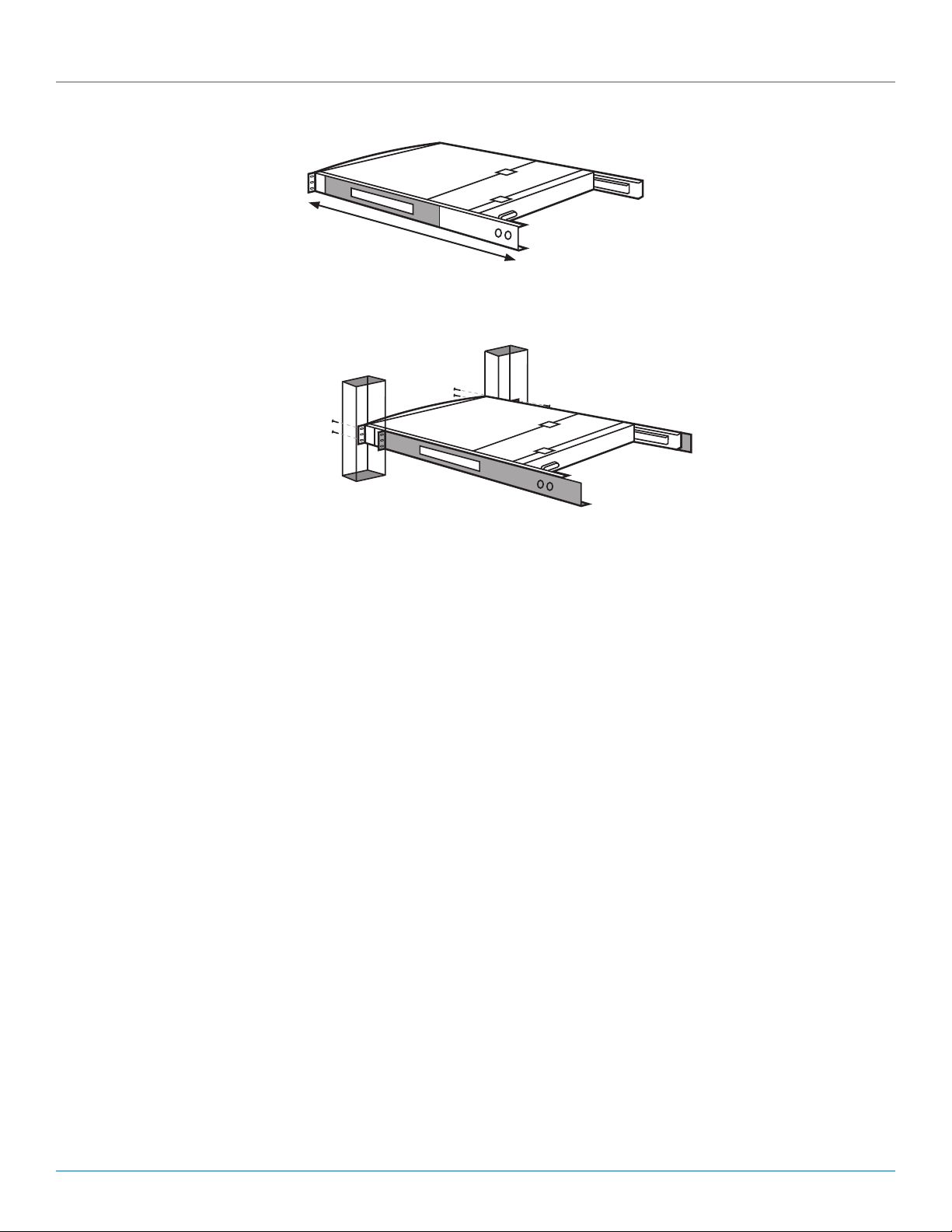
Control your 4-post-rack- or cabinet-mounted USB or PS/2®server with the compact, easy-to-use ServTray. It consists of a
keyboard, mouse, LCD panel, and KVM module housed in an industry-standard 19" 1U-height rack drawer (see Figure 2-1).
Three models are available: the ServTray with a 15" LCD panel (KVT415A-R2), the ServTray with a 17" LCD panel (KVT417A-R2),
and the ServTray with a 19" LCD panel (KVT419A-R2). All models feature a full 105-key, low-profile, sturdy keyboard and touch
pad with an ergonomically designed hand rest. The KVT415A-R2 has a maximum resolution of 1024 x 768, and the KVT417A-R2
and KVT419A-R2 have a maximum resolution of 1280 x 1024.
Install the ServTray in 4-post racks or cabinets that are 23.7" to 45.3"D (60.2 to 115.1 cm). When installing the ServTray, you’ll
need to use the Universal Rear Mounting Brackets (described in Section 2.4) that are included in your ServTray Kit.
A KVM module is also included with the ServTray. To control more than one USB or PS/2 server, connect the ServTray to one of
the other KVM tray modules listed above.
The KVM module comes with a universal Centronics®36-pin connector; use it to connect the module to the console drawer. The
module has a barrel connector for power (or a locking power connector for the CATx modules). The large screws are used in
place of 10-32 or 12-24 screws (described in Chapter 3, not included) if required by your rack.
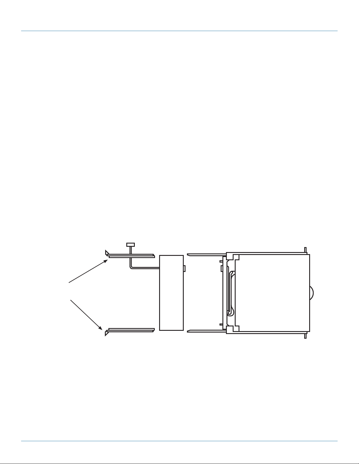
Power supply
*KVM module
(see NOTE below)
Universal rear
mounting brackets
1U slide drawer with
keyboard, touch pad,
and 15", 17", or 19"
LCD monitor
(KVT415A-R2,
K V T417A-R2, or
KVT419A-R2)
*NOTE: KVM modules include KVT6S1UV, KVT4S8PV, KVT4S8UV, KVT4S16PV, KVT4S16UV, KVT8DVIU, KVT1IP1UV, KVT1IP81UV,
KVT1IP16UV, KVT8CATUV, KVT16CATUV, KVT1IP8CATUV, KVT1IP16CATUV, and KVT4IP16CATUV.
Figure 2-1. ServTray Kit components (left to right): Uiniversal rear mounting brackets,
KVM Module with power supply, and 1U slide drawer.
2.2 What’s Included
• (1) ServTray 15", 17", or 19" LCD console (LCD panel, keyboard, and mouse pad console drawer)
• (1) KVM module with power supply (based on product code)
• (1) universal rear rail kit (includes [2] brackets, [2] extensions, and [8] screws)
• (10) 0.19" x 0.43" (0.5 x 1.1 cm) screws

724-746-5500 | blackbox.com
Page 8 KVT415A-R2
724-746-5500 | blackbox.com
Chapter 2: Overview
• (10) 0.12" x 0.24" (0.3 x 0.6 cm) screws
• This user’s manual
Accessories that you might or will need to purchase include:
• 12-24 or 10-32 nuts/bolts (you might need these to mount the KVM tray in the rack/cabinet)
2.3 KVM Switch Module Compatibility
• KVT6S1UV (1-Port DVI/VGA USB and PS/2 Module, part number KVT6S1UV with user’s manual)
• KVT4S8PV (8-Port VGA USB and PS/2 Module, part number KVT4S8PV with user’s manual)
• KVT4S8UV (8-Port VGA USB and PS/2 Module, part number KVT4S8UV wiht user’s manual)
• KVT4S16PV (16-Port VGA PS/2 Module, part number KVT4S16PV with user’s manual)
• KVT4S16UV (16-Port VGA USB and PS/2 Module, part number KVT4S16UV with user’s manual)
• KVT1IP1UV (1-Port USB and PS/2 IP enabled Module, part number KVT1IP1UV with user’s manual)
• KVT1IP8UV (8-Port VGA USB and PS/2 IP enabled Module, part number KVT1IP8UV with user’s manual)
• KVT1IP16UV (16-Port VGA USB and PS/2 IP enabled Module, part number KVT1IP16UV with user’s manual)
• KVT8CATUV (8-Port CX CATx Module, part number KVT8CATUV with user’s manual)
• KVT16CATUV (16-Port CX CATx Module, part number KVT16CATUV with user’s manual)
• KVT1IP8CATUV (8-Port CX CATx Module, part number KVT1IP8CATUV with user”s manual)
• KVT1IP16CATUV (16-Port CX CATx Module, part number KVT1IP16CATUV with user’s manual)
• KV4IP16CATUV (16-Port CX CATx Module, part number KVT4IP16CATUV with user’s manual)
2.4 Universal Rear Mounting Brackets
Figure 2-2 shows the rear bracket pair, and Figures 2-3 and 2-4 show the ServTray in its maximum and minimum extension
positions.
Figure 2-2. Rear bracket pair.
NOTE: The lengths in Figures 2-3 and 2-4 are the depths measured between the front pole and rear pole inside a 4-post rack or
cabinet, not the outside depth of the enclosure.
45.3"
(115.1 cm)
Figure 2-3. The maximum depth of the unit.

724-746-5500 | blackbox.com
724-746-5500 | blackbox.com Page 9
KVT415A-R2
Chapter 2: Overview
23.7"
(60.2 cm)
Figure 2-4. The minimum depth of the unit.
Open rack
post 1
Open rack
post 2
ServTray
Figure 2-5. ServTray installed on an open rack.

724-746-5500 | blackbox.com
Page 10 KVT415A-R2
724-746-5500 | blackbox.com
Chapter 3: Assembly and Installation
3. Assembly and Installation
1. Choose a proper position in the cabinet for the rack drawer.
2. Using eight counter-sunk screws (included), attach the extensions (included with your ServTray kit) to both sides of the KVM
switch module. See Figures 3-1 through 3-5. The wide-edged plastic extension should be on the top side (see Figure 3-5).
NOTE: The CATx KVM Switch Modules will only accept between (2) and (4) mounting screws on each extension, depending on
kit part numbers.
Rear brackets
Extensions
Figure 3-1. Rear brackets and extensions.
KVM module
Extensions
(4) counter-sunk
screws
Figure 3-2. Extensions and KVM module.
Extension
Switch module
Figure 3-3. Attaching the extensions to one side of the KVM switch module.

724-746-5500 | blackbox.com
724-746-5500 | blackbox.com Page 11
KVT415A-R2
Extension on side
of switch module Switch module
Figure 3-4. KVM switch module with extensions attached.
KVT6S1UV
The wide-edged
plastic extension
should be on the
top side.
NOTE: Unit may appear
different based
on ordering options.
Figure 3-5. Back view of module with extensions attached.
Chapter 3: Assembly and Installation

724-746-5500 | blackbox.com
Page 12 KVT415A-R2
724-746-5500 | blackbox.com
Chapter 3: Assembly and Installation
3. Remove the safety stopper from the console drawer (see Figure 3-6). The safety stopper keeps the drawer from sliding out
during transportation.
Console drawer
Safety stopper
Figure 3-6. Locating and removing the safety stopper.
WARNING: After the safety stopper is removed, the drawer may slide out when tilted. This could cause serious injury; keep the
drawer assembly level to avoid this.
4. Slide the rear bracket into both sides of the unit. Make sure that the two wheels with screws are inside the bracket’s track
while sliding in the rear bracket. See Figure 3-7.
ServTray
Rear bracket
Rear bracket
Bracket track
Figure 3-7. Install the rear bracket onto the ServTray KVM Tray’s extensions.

724-746-5500 | blackbox.com
724-746-5500 | blackbox.com Page 13
KVT415A-R2
Chapter 3: Assembly and Installation
5. Use four 10-32 or 12-24 screws (not included) to fasten the console drawer onto the front brackets. (See Figure 3-8.) The metal
brackets shown in the figure support the console’s rear side.
Rear bracket
Front bracket
Front bracket
Console drawer
Figure 3-8. Securing the console drawer to the cabinet’s front brackets.
6. Push the KVM switch module evenly towards the drawer. See Figure 3-9.
Figure 3-9. Pushing the module towards the drawer.

724-746-5500 | blackbox.com
Page 14 KVT415A-R2
724-746-5500 | blackbox.com
Chapter 3: Assembly and Installation
7. Slide out the console drawer. Push the KVM module evenly toward the drawer and secure both units using the attached
thumbscrews. See Figure 3-10.
Thumbscrews (permanently
attached to the tray)
Console drawer
KVM module
Figure 3-10. Securing the KVM module to the console drawer.
8. Make sure the Centronics connectors on the KVM module and attached cable are firmly mated. See Figure 3-11.
Centronics
connector
on cable
5⁄16" (8 mm)
Figure 3-11. Centronics connectors.
9. Connect the power supply to the barrel connector on the KVM module.
10. For operation, pull out the drawer from the 4-post rack or cabinet and latch it in the extended position. A locking mechanism
locks the drawer when it’s pulled out, pushed in, or folded down. When not in use, push in the drawer, then fold down, lock,
and secure the display.

724-746-5500 | blackbox.com
724-746-5500 | blackbox.com Page 15
KVT415A-R2
Chapter 3: Assembly and Installation
11. Once the ServTray is installed in the 4-post rack or cabinet, you can connect it to a computer. The KVM module’s connectors
attach to the KVM connectors on a PS/2 CPU via the 3-in-1 (PS/2, PS/2, VGA) Cable (included), or they connect to the HD15
and keyboard/mouse connectors on a USB CPU via the 2-in-1 (USB, VGA) Cable (included), or they connect to the DVI and
keyboard/mouse connectors on a USB CPU via the 2-in-1 (USB, DVI) cable. All cables are shown in Figure 3-12. If you choose
to use the Digital Video Interface, connect the DVI cable between the target PC and the KVM Switch Module.
2-in-1 Cable
(included)
3-in-1 Cable
(included)
HD15 female
connector
(2) 6-pin mini DIN
male connectors
(2) 6-pin mini DIN
male connectors
HD15 male
connector
HD15 female
connector
HD15 male
connector
USB Type B
connector
USB Type A
connector
This side connects
to the computer/
server.
This side attaches to
the ServTray unit’s
KVM module.
This side attaches
to the ServTray
unit’s KVM
module This side connects
to the computer/
server.
2-in-1 Cable
(included)
USB Type B
connector
USB Type A
connector
DVI-I male
connector
DVI-I male
connector
This side attaches
to the ServTray
unit’s KVM
module
This side connects
to the computer/
server.
Figure 3-12. Cable for connecting the KVM module to a computer.
NOTE: These cables are included only with the 1-Port VGA/DVI PS2/USB (KVT6S1UV) module. All other modules have the VGA/
PS2 and VGA/USB cables.

724-746-5500 | blackbox.com
Page 16 KVT415A-R2 724-746-5500 | blackbox.com
Chapter 4: Operation
4. Operation
Once the ServTray is installed and connected to a PS/2 or USB CPU or ServSwitch, it’s ready for operation. Control the unit via the
buttons on the LCD panel (labeled 1 and 2 in Figure 4-1) and the LCD panel power switch (labeled 3 in Figure 4-1). Monitor the
status via the keyboard status indicators (labeled 4, 5, and 6 in Figure 4-1).
1
6
5
4
3
2
1
2
Figure 4-1. The ServTray’s components.
1. Use the LCD panel menu buttons (1 in Figure 4-1) to activate the OSD menu to set the LCD panel as an ordinary LCD montior.
2. Use the LCD panel adjustment buttons (2 in Figure 4-1) to adjust settings for the LCD panel.
3. Switch the power to the LCD panel on or off via the power switch (3 in Figure 4-1).
4. Use the keyboard status indicators (Num Lock, Caps Lock, and Scroll Lock) to view status.
• The Num Lock Key LED (labeled 4) shows the Keyboard Num Lock Status (on or off).
• The Caps Lock Key LED (labeled 5) shows the Keyboard Caps Lock Status (on or off).
• The Scroll Lock Key LED (labeled 6) shows the Keyboard Scroll Lock Status (on or off).
5. Use the touch pad (see Figure 4-2) to simulate a wheel mouse. The touch pad’s area to the right side of the two small
triangular marks is the simulated scroll area. Move your finger along this area to scroll up or down on the computer’s screen.
The touch pad area enables you to move the cursor anywhere on your computer’s screen by sliding your finger along this area.
Area for
touch pad
Left button
Area for
scroll wheel
Right button
Figure 4-2. Touch pad.

724-746-5500 | blackbox.com 724-746-5500 | blackbox.com Page 17
Chapter 5: Troubleshooting
5. Troubleshooting
5.1 Contacting Black Box
If you determine that your ServTray is malfunctioning, do not attempt to alter or repair the unit. It contains no user-serviceable
parts. Contact Black Box Technical Support at 724-746-5500 or info@blackbox.com.
Before you do, make a record of the history of the problem. We will be able to provide more efficient and accurate assistance
if you have a complete description, including:
• the nature and duration of the problem.
• when the problem occurs.
• the components involved in the problem.
• any particular application that, when used, appears to create the problem or make it worse.
5.2 Shipping and Packaging
If you need to transport or ship your ServTray:
• Package it carefully. We recommend that you use the original container.
• If you are returning the unit, make sure you include everything you received with it. Before you ship for return or repair,
contact Black Box to get a Return Authorization (RA) number.

724-746-5500 | blackbox.com
Page 18 KVT415A-R2
724-746-5500 | blackbox.com
NOTES

724-746-5500 | blackbox.com
724-746-5500 | blackbox.com Page 19
KVT415A-R2
NOTES

724-746-5500 | blackbox.com
About Black Box
Black Box Network Services is your source for an extensive range of networking and infrastructure products. You’ll find everything
from cabinets and racks and power and surge protection products to media converters and Ethernet switches all supported by
free, live 24/7 Tech support available in 30 seconds or less.
© Copyright 2011. All rights reserved.
BLACK BOX®
Black Box Tech Support: FREE! Live. 24/7.
Tech support the
way it should be.
Great tech support is just 30 seconds away at 724-746-5500 or blackbox.com.
KVT415A-R2, version 2
This manual suits for next models
2
Table of contents
Other Black Box Computer Accessories manuals