724-746-5500 | blackbox.com724-746-5500 | blackbox.com 724-746-5500 | blackbox.com
FOPM-210 and FOPM-250 Quick Start Guide FOPM-210 and FOPM-250 Quick Start GuideFOPM-210 and FOPM-250 Quick Start Guide
Page 3Page 2 Page 4
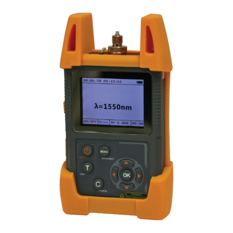
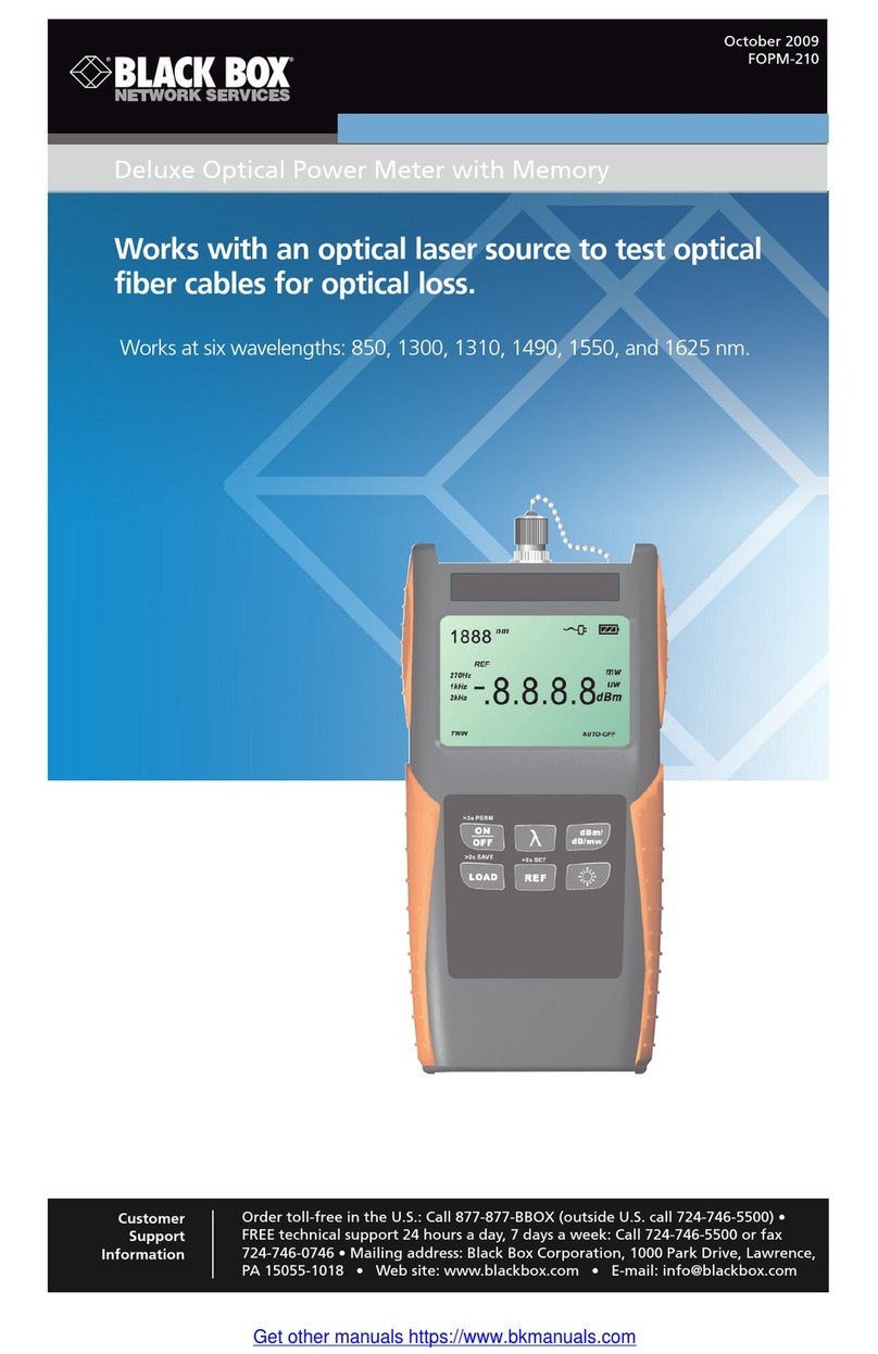
1. Display and Keypad
Figure 1 shows the optical power meter’s display and
keypad.
Interchangeable
connector
LCD screen
Figure 2 shows the power meter’s LCD display and
Table 2 describes its functions. Table 3 shows the
battery indicator status.
2
8
1
65
3
7
9
Figure 2. LCD.
Table 2. LCD functions.
Number Function
1 Wavelength Reference
2 AC adapter
3 Battery charge
4 Measurement unit
5 Auto-off
6 Power value
7 Frequency
8 Reference value
9 Auto-wavelength
recognition
Table 3. Battery indicator status.
Status Icon Description
Full Battery at 100% capacity
2 Bars Battery at 50–75% capacity
1 Bar Battery at 25–50% capacity
Empty Battery at 0–25% capacity*
* Battery icon flashes when power is almost depleted.
Connect the AC adapter to recharge the battery.
2. Keypad Functions, LCD Functions, and
Battery Indicator Status
Table 1 describes the optical power meter’s keys.
Table 1. Keypad functions.
No. Key Function
Number Key Function
1 Switches tester on/off. Press and
hold for more than two seconds
while turning on to disable the
auto-off feature.
2 Press to set the wavelength.
Select from six possible wave-
lengths: 850, 1300, 1310, 1490,
1550, and 1625 nm. Press and
hold to activate auto-wavelength
recognition.
3 Press to select the measurement
mode. Three modes are available:
dBm for the power value, dB for
the relative value, and mw for the
logarithmic value. (HI/LO will be
displayed if the measured power
value is out of range.)
4 Press to display the last record
stored. Press and hold to store
the current test value.
5 Press for less than two seconds to
display the wavelength reference
level. Press and hold for two more
seconds to set a new wavelength
reference level.
6 Press to switch backlighting on/
off.
Figure 1. Display and keypad.
DC input jack
Battery fully charged LED
External power/
recharging LED
Figure 2. Bottom of power meter.
4
1
2
3
4
5
6
