Page 6 724-746-5500 | blackbox.com
Page 7
724-746-5500 | blackbox.com
Installation ProcedureDFCS XG Standalone
This User Manual describes the functions of the DFCS XG Rev 2.0.
Product Overview
The DFCS XG is a 10 Gigabit, protocol-transparent media converter with two pluggable
transceiver ports. The DFCS XG can be used as a copper-to-ber converter, a ber mode
converter, a WDM transponder or a ber repeater supporting the three Rs (regeneration,
retiming and reshaping).
The DFCS XG can be used in Telecom or Enterprise applications where 10 Gigabit media
conversion and ber extension is required. The product supports 100% trafc throughput
and has no packet size restrictions.
XFP to XFP (LMC11002A)
XFP to XFP models are protocol transparent within the range of 9.95Gbps to 11.32Gbps,
providing interoperability with common protocols including: 10G Ethernet, 10G SONET/SDH,
10G Fibre Channel and 10G OTN (G.709).
XFP to XFP models support two types of XFP transceivers - those which provide internal
clocking (more common) and those which require an external clock source (less common).
The transceivers installed in the LMC11002A must have matching speeds.
If both XFPs are internally clocked, the XG will automatically support rates from 9.9Gbps to
11.3Gbps.
If one or both transceivers requires external clocking, the XG will support rates from 9.9Gbps to
11.3Gbps. In this case, the user must select the speed using the DIP switches in Figure 3.
SFP+ to XFP (LMC11022A)
SFP+ to XFP models are compatible with 10G Ethernet only.
SFP+ to SFP+ (LMC11012A)
SFP+ to SFP+ models are compatible with 10G Ethernet only.
Installation Procedure
1) Congure DIP-switches
2) Install Standalone Module and Connect Cables
3) Verify Operation
1) CONFIGURE DIP-SWITCHES
DIP-SWITCH BANK 1
The location of DIP-switch Bank 1 is on the front of the module between the two ports.
The function of DIP-switch Bank 1 is outlined in Figure 1.
Figure 1: DIP-switch BANK 1 Denitions
SW1 - P1 LOOPBACK “P1-LB”
When this DIP-switch is in the DOWN position (factory default), Port 1 (P1) Loopback is
disabled. When this DIP-switch is in the UP “P1-LP” position, Loopback is enabled on P1.
When enabled, all data received on P1 is transmitted out P1 and all data received on Port 2
(P2) is dropped. No data is transmitted on P2 when Loopback is enabled on P1.
SW2 - P2 LOOPBACK “P2-LB”
When this DIP-switch is in the DOWN position (factory default), P2 Loopback is disabled. When
this DIP-switch is in the UP “P2-LP” position, Loopback is enabled on P2. When enabled, all
data received on P2 is transmitted out P2 and all data received on P1 is dropped. No data
is transmitted on P1 when Loopback is enabled on P2.
NOTE: For the LMC11002A models, the availability of the Loopback feature is dependent
on the capability of the installed XFP. XFPs with XFI-side Loopback feature are required.
Simultaneous Loopback of P1 and P2 is not supported on the XFP/SFP+ and XFP/XFP
models.
SW3, SW4 - RATE SELECTION
These switches are for XFP to XFP (LMC11002A) model only with XFP transceivers requiring
external clocking. All other congurations including LMC11022A, LMC11012A and the
LMC11002A with internal clocking XFPs must use the factory default setting of DOWN +
DOWN.
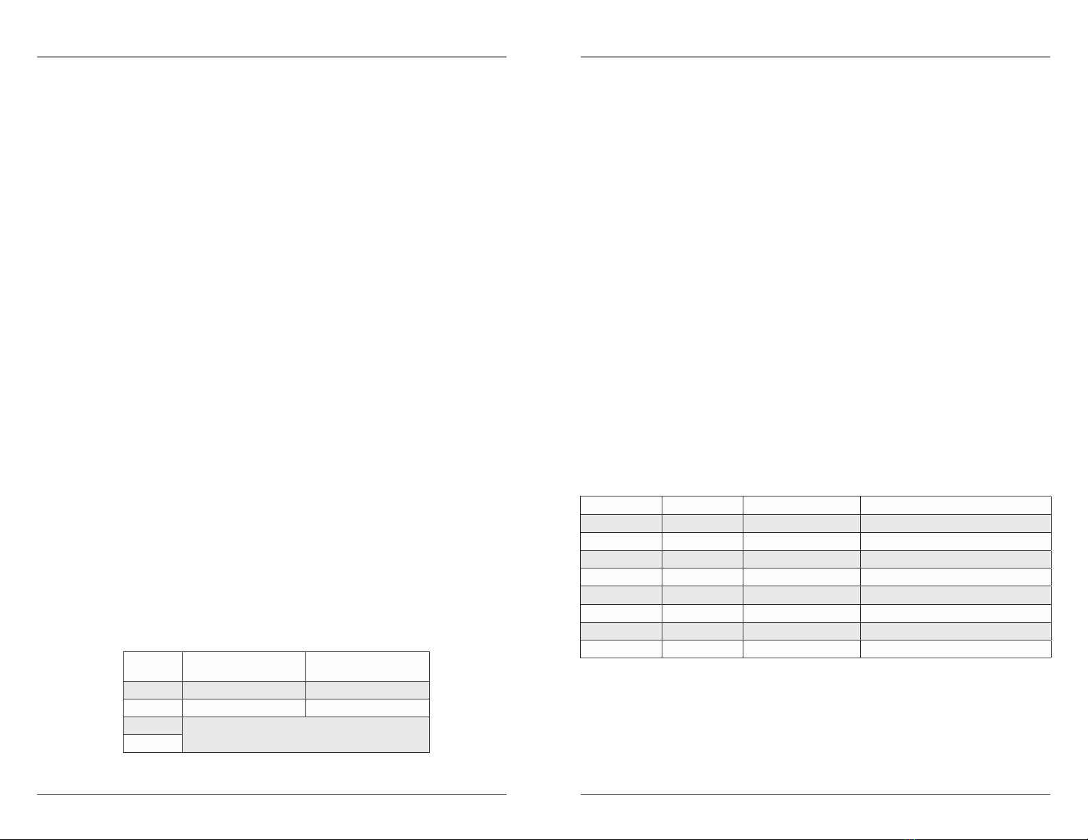
These two switches, in conjunction with Jumper J6, congure the operating data rate of
the XG with XFPs requiring external clocking. Congure the module to the data rate that
corresponds to the transport protocol used.
Jumper “J6” is located on the module directly behind DIP switch Bank 1. The jumper is Open
by default. To change the jumper setting, use a Phillips screwdriver to remove four screws
which secure the covert to the base. Remove the cover to access the jumper.
Jumper “J6” SW3 SW4 Speed Mode
Open LEFT/DOWN LEFT/DOWN 10G Ethernet (10.3125 Gb/s)
Open LEFT/DOWN RIGHT/UP 10G SONET/SDH (9.95328 Gb/s)
Open RIGHT/UP LEFT/DOWN 10G Fiber Channel (10.51875 Gb/s)
Open RIGHT/UP RIGHT/UP 10G OTN (G.709) (10.70923 Gb/s)
Closed LEFT/DOWN LEFT/DOWN 10GbE w/ FEC (11.049 Gb/s)
Closed LEFT/DOWN RIGHT/UP 10GbE w/ FEC stuff bytes (11.095 Gb/s)
Closed RIGHT/UP LEFT/DOWN 10GbFC w/ FEC (11.270 Gb/s)
Closed RIGHT/UP RIGHT/UP 10GbFC w/ FEC stuff bytes (11.317 Gb/s)
Figure 2: DIP-switch BANK 1 Rate Selection
Switch LEFT/DOWN
(Default) RIGHT/UP
SW1 Normal P1 Loopback Enabled
SW2 Normal P2 Loopback Enabled
SW3 Rate Selection
(See Figure 3)
SW4