manuals.online logo
Brands
  1. Home
  2. •
  3. Brands
  4. •
  5. Black Box
  6. •
  7. Modem
  8. •
  9. Black Box ME375A User manual

Black Box ME375A User manual

ME375A
ANAREMPATT
INTERFACE CONN.
PWRRTSTDRDDCDTEST
BLACK BOX
RESET
PATTREMANADIG
TESTDCD LOS ERRRDTDRTSPWR
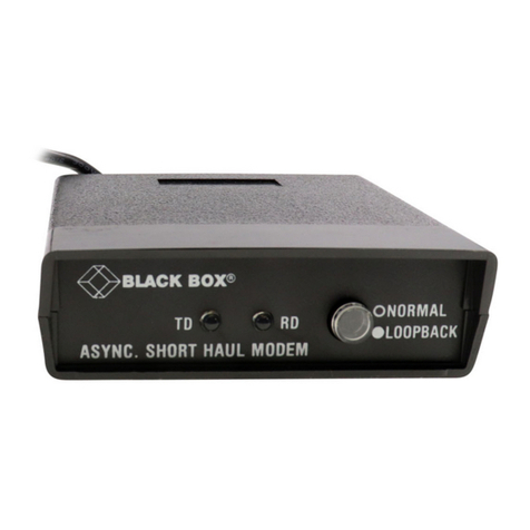
ASYNC/SYNC 2-WIRE SHORT HAUL MODEM
DIG
ERR LOS
1 2 3 4 5 6 7 8
9
DATA RATE
SELECTION 0 = 600 bps
1 = 1.2 Kbps
2 = 2.4 Kbps
3 = 4.8 Kbps
4 = 9.6 Kbps
5 = 19.2 Kbps
6 = 38.4 Kbps
7 = 48 Kbps
8 = 56 Kbps
9 = 64 Kbps
A = 128 Kbps
POS BAUD EXT
INT
LBT
CLK SOURCE
DIS
EN
DIS
EN
CHASSIS GND
DIS
CON
Interfaces: ME375 models: 2-wire telco, EIA RS-232;
ME376 models: 2-wire telco, ITU-TSS (CCITT) V.35
Protocols: DTE side: Synchronous or Asynchronous
Line side: 2B1Q encoding
Clock Source: Internal, External (from DTE), or received (from other unit), user-selectable.
Data Format: 7 or 8 data bits; 1 or 2 stop bits; even, odd, or no parity (user-selectable).
Operation: Line side: Full duplex with echo cancellation.
Data Rate: 128, 64, 56, 48, 38.4, 19.2, 9.6, 4.8, 2.4, 1.2, or .6 Kbps.
Transmission Level: Up to 14 dBm.
User Controls: (5) Front-mounted:
(4) Pushbuttons: DIG (local digital loopback), ANA (local analog loopback),
REM(remote digital loopback), and PATT (test pattern);
(1) Recessed RESET switch;
(6) Internal Jumpers:
(1) 7-position DIP switch for protocol, data format, and signaling options;
(1) Rotary switch for data rate;
(4) Jumpers for clock source, loopback testing, and ground connection.
Diagnostics: V.54--compliant loopback tests:
Local analog loopback (switch- or signal-triggerable);
Local digital loopback (switch-triggerable);
Remote digital loopback (switch- or signal-triggerable).
Connectors: ME375 models: (1) RJ-45 female, (1) 3-clip terminal block, and (1) DB25 female;
ME376 models: (1) RJ-45 female, (1) 3-clip terminal block, and (1) 34-pin M-block female.
Power: From internal power supply through included or alternate 5-ft. (1.5m) power cord:
Input: 103.5 to 131.5 VAC, 47 to 63 Hz
Output: 5VA
LINE
4 52
GND
1. Insert screwdriver into square hole.
2. Raise inserted screwdriver, putting
pressure on the ramp within the square
hole. The wire clamp within the round
hole will open.
3. Insert the stripped end of the wire and
remove the screwdriver.
INSERTING WIRE INTO THE CLIPS
INTRODUCTION:
The Async/Sync 2-Wire Short Haul Modem (A/S2W SHM) operates synchronously or asynchronously at high speeds (600 bps to 128 Kbps) and in full duplex over one pair of dedicated telephone lines. It has a range of 3.4 miles (5.5 km) over 26-AWG
wire. The A/S2W SHM operates in full duplex over 2 wires by using the adaptive "echo-canceling" technique. Because it also uses 2B1Q line coding, it can achieve the range mentioned above no matter what the data rate is.
The A/S2W SHM incorporates interface circuits for the terminal/computer, an adaptive echo-canceler, an automatic adaptive equalizer, a modulator, and a demodulator. It is couples to the telephone line through an isolation transformer, which protects
against AC or DC overvoltages. The protection circuitry would enable the unit to operate even if DC were accidentally connected to the line.
The A/S2W SHM has diagnostic capabilities: It can perform local analog loopback and local and remote digital loopback. The operator at either end of the line may test both modems and the line in the remote digital loopback mode. Loopback can be
controlled with either the unit's front-panel pushbuttons or signals passed through the DTE (PC, data-terminal) interface.
CONFIGURATION AND INSTALLATION:
PLACEMENT:
The Async/Sync 2-Wire Short Haul Modem is designed to be placed on a tabletop, shelf, or bench, and is delivered completely assembled. (No provisions are made for bolting the A/S2W SHM to any surface). The A/S2W SHM should be installed
within 1.5 m (5 ft) of a grounded AC outlet and must be situated within 25 ft. (7.6 m--ME376 models) or 50 ft. (15 m--ME375models) of the associated data terminal. Allow at least 36" (90 cm) of clearance in front of the unit so you can access it
during operation and maintenance. Make sure that there is at least 4" (10 cm) of clearance behind the unit for signal lines and interface cables.
SETTING THE INTERNAL CONTROLS:
Before you install any cabling and definitely before you plug in the unit, you should set the Async/Sync 2-Wire Short Haul Modem's internal controls to suit your application. (If you don't feel comfortable about doing this yourself, get an experienced
technician to do it or to help you). To access the internal controls, first make sure the unit is disconnected from the AC power, then unscrew the two screws on the unit's rear panel and slide the bottom half of the unit out form beneath its cover.
CONNECTING THE DATA CABLES:
1. Connect the twisted-pair transmission line to the two clips marked LINE (or Pins 4 and 5 of the RJ-45 connector) and (optionally) the cable shield to the clip marked GND (or Pin 2 of the RJ-45 connector). If you are using the connecting line to
the clips, refer to the Wire-Insertion Details on the first page. We highly recommend that for your transmission line you use twisted-pair cable capable of supporting high data rates, especially Category 3 or better, in order to prevent crosstalk.
Our product code for a type of cable that fits the bill, bulk unterminated Category 5 UTP, is EYN717A (specify the length you want).
2. Run the DTE-side cable from the DTE to the A/S2W SHM. If your A/S2W SHM is an ME375 model, this cable should be straight-through-pinned and 50 or fewer feet (15.2 or fewer meters) long; it should also have a DB25 female connector on
the DTE end and a DB25 male connector on the A/S2W SHM end. (Our product code for this type of cable is ECM25C; specify the length you want and "male-female" genders).
If your A/S2W SHM is an ME376 model, this cable should be straight-through-pinned and 25 or fewer feet (7.6 or fewer meters) long; it should also have a 34-pin M-block male connector on the A/S2W SHM end. (Our product code for this type
of cable is EYN450; specify the length and genders you want).
OPERATION:
On page 1, shows the front panel of the Async/Sync 2-Wire Short Haul Modem, including all of the controls and LED indicators mounted on it. These controls and indicators are described below.
DIG: Press this Local Digital Loopback button to cause the local unit to loop received data and clock signals from the line back out of its own transmitter. This is equivalent to activating remote digital loopback on the remote unit. Press this button
again to terminate local digital loopback.
ANA*: Press this Local Analog Loopback button to cause the local unit to loop its transmitter output back into its own receiver. Press this button again to terminate local analog loopback. while the unit's LLB jumper is set to EN, you can also control
this type of loopback by raising and lowering the LL signal from the DTE on the appropriate pin for your interface.
REM*: Press this Remote Digital Loopback button to cause the remote unit to loop received data and clock signals back out of its own transmitter. (Data Set Ready goes low when this happens). Press this button again to terminate remote digital
loopback. While the unit's RLB jumper is set to EN, you can also control this type of loopback by raising and lowering the RL signal from the DTE on the appropriate pin for your interface.
PATT: Press this Pattern button to cause the local unit to send the remote unit a continuous Bit Error Rate Test Pattern. Press this button again to stop sending the test pattern.
RESET: Carefully press a long thin object such as a tack or the end of a paper clip into this recessed switch to reset the unit. Do this to clear abnormal conditions (the indication of an error condition, for example) instead of unplugging the unit and
plugging it back in.
* The ANA and REM buttons are not affected by the settings of the RLB and LLB jumpers. Even if those jumpers are set to DIS (Disabled), you can still control loopback testing with these buttons.
Continued on next page.
FRONT-PANEL INDICATORS AND THEIR FUNCTIONS:
PWR: Green LED is steadily lit while power is present.
RTS: Yellow LED is steadily lit while the Request to Send (RTS) signal from the DTE is high.
TD: Yellow LED is steadily lit while the local unit transmits steady SPACE. It flickers while the local unit transmit data.
RD: Yellow LED is steadily lit while the local unit receives steady SPACE. It flickers while the local unit receives data.
DCD: Yellow LED is steadily lit while:
a.) The local and remote units are in sync, and the local unit's DCD switch is set to "DCD"
b.) The local and remote units are in sync, the local unit's DCD switch is set to "CNT", and the remote unit has RTS high.
LOS: Red LED is steadily lit when synchronization between the local and remote units are lost.
ERR: Red LED is steadily lit when the local units PATT button is in the ON position (depressed) and the unit detects an error in the BERT pattern.
TEST: Yellow LED is steadily lit while the local units internal BERT is active (the PATT button is depressed) or the unit is in any of the three loopback modes.
POWER-UP, NORMAL OPERATION, AND POWER DOWN:
Making sure that you follow the guidelines in the previous section, power up the Async/Sync 2-Wire Short Haul Modem by plugging its AC power cord to an working AC outlet. (The unit has no power switch. To power it down, unplug it). The PWR LED
should light, indicating that the unit is on. If the local and remote A/S2W SHM units are both operating and transmitting data, the unit's front-panel indicators should look like this:
PWR: Steadily lit
TD: Steadily lit or flickering depending on the data being transmitted.
RD: Steadily lit or flickering depending on the data being received.
RTS: Steadily lit or dark depending on the status of the RTS signal from the local DTE.
DCD: If the local unit's DCD jumper is set to DCD, steadily lit; if the local unit's DCD jumper is set to CNT,
steadily lit or dark depending on the status of the RTS signal from the remote unit.
LOS: Flashing until the units synchronize with each other, then dark.
ERR: Flashing until the units synchronize with each other, then dark.
TEST: Flashing until the units synchronize with each other, then dark.
If the LED's don't look like this, make sure that:
1. One A/S2W SHM's CLOCK jumper is set to internal (INT) or external (EXT) clock, and the other units CLOCK jumper is set to loopback (LBT) clock.
2. Both units four front-panel pushbuttons are in the OFF position (not depressed).
Once a A/S2W SHM begins operating normally, it will continue to do so indefinitely without needing to be attending, except when occasional monitoring of LED indicators is required.
POSITION/LABEL POSSIBLE SETTINGS FACTORY DEFAULT
Position 1 Async or Sync Operation Sync
ON = ASYNC
OFF = SYNC
Position 2 8 or 7 Data Bits 8 bits
ON = 8 bits
OFF = 7 bits
Position 3 Parity Enabled/Disabled Disabled
ON = Enabled
OFF = Disabled
Position 4 Even or Odd parity Even
ON = Even
OFF = Odd
Position 5 1 or 2 stop bits 1 bit
ON = 1
OFF = 2
Position 6 * DCD independent or controlled by RTS DCD independent
ON = DCD
OFF = CNTL
Position 7 ** DSR always ON or follows DTR DSR ON
ON = DSR
OFF = DTR
* If DIP Switch Position 6 is set to :
1.) DCD: The DCD signal is ON as long as the local unit is in proper
synchronization with the remote unit. The DCD signal is OFF when
digital loopback is active or when there is no synchronization (for
example, while the unit is receiving the remote loopback command).
2.) CNT: The local unit's DCD signal follows the remote unit's RTS signal.
** If DIP Switch Position 7 is set to:
1.) DSR: The DSR signal is ON as long as the local unit is receiving AC
power; it does not indicate the existence of a communication channel
or the status of the remote site.
2.) DTR: The local unit's DSR signal follows the remote unit's DTR signal.
FUNCTION/LABEL POSSIBLE SETTINGS FACTORY DEFAULT
Clock-Source (CLOCK) Jumper For master units, select either INT
internal timing (INT) or external
timing (EXT).
For slave units, always select
loopback (received) timing (LBT)
Local Loopback (LLB) Jumper Enable/Disable control of local DIS
analog loopback testing with
signals from the DTE.
Remote Loopback (RLB) Jumper * Enable/Disable control of remote DIS
digital loopback testing with signals
from the DTE.
Chassis Ground (CHASS_GND) Tie Signal Ground to Chassis CON
Jumper (Protective, Frame) Ground or
isolate the two grounds from
each other.
Only connect the RLB and LLB jumpers (that is, set them to EN [enabled]) if you want to be able to turn local
analog or remote digital loopbacks on and off from the DTE using the proper RS-232 or V.35 signals. The
settings of these jumpers have no effect on the ANA and REM pushbutton switches on the unit's front-panel; you
will be able to control loopback testing with those buttons whether these jumpers are connected or not. (There
is no way to control local digital loopback through the local DTE interface; you must use the DIG button to do
that.)
DIP SWITCH SETTINGS:
Other Black Box Modem manuals

Black Box Tote-a-Fax 542 User manual

Black Box

Black Box Tote-a-Fax 542 User manual

Black Box MDS932AE-10BT User manual

Black Box

Black Box MDS932AE-10BT User manual

Black Box MD1276A User manual

Black Box

Black Box MD1276A User manual

Black Box SHM 128 User manual

Black Box

Black Box SHM 128 User manual

Black Box ME260A User manual

Black Box

Black Box ME260A User manual

Black Box MDR220A User manual

Black Box

Black Box MDR220A User manual

Black Box 32457 User manual

Black Box

Black Box 32457 User manual

Black Box SHM-NPR User manual

Black Box

Black Box SHM-NPR User manual

Black Box MDR24x User manual

Black Box

Black Box MDR24x User manual

Black Box ME1240A-F User manual

Black Box

Black Box ME1240A-F User manual

Black Box MD1620A User manual

Black Box

Black Box MD1620A User manual

Black Box ME801A User manual

Black Box

Black Box ME801A User manual

Black Box ME570A-MST-R2 User manual

Black Box

Black Box ME570A-MST-R2 User manual

Black Box ME800A-R2 User manual

Black Box

Black Box ME800A-R2 User manual

Black Box ME0002A-V35 User manual

Black Box

Black Box ME0002A-V35 User manual

Black Box MT240A-R2 User manual

Black Box

Black Box MT240A-R2 User manual

Black Box MD1970A User manual

Black Box

Black Box MD1970A User manual

Black Box MD5010A User manual

Black Box

Black Box MD5010A User manual

Black Box 40418 User manual

Black Box

Black Box 40418 User manual

Black Box ME570A-MST User manual

Black Box

Black Box ME570A-MST User manual

Black Box 3600 User manual

Black Box

Black Box 3600 User manual

Black Box SME-422 User manual

Black Box

Black Box SME-422 User manual

Black Box Mobile Linc-Up User manual

Black Box

Black Box Mobile Linc-Up User manual

Black Box TL304A User manual

Black Box

Black Box TL304A User manual

Popular Modem manuals by other brands

Telit Wireless Solutions FT980 Series user guide

Telit Wireless Solutions

Telit Wireless Solutions FT980 Series user guide

ATL AM2048A OS user guide

ATL

ATL AM2048A OS user guide

Vernier VE user manual

Vernier

Vernier VE user manual

NetComm Vodafone MachineLink 3G Configuration guide

NetComm

NetComm Vodafone MachineLink 3G Configuration guide

Four-Faith F2203 user manual

Four-Faith

Four-Faith F2203 user manual

Huawei webConnect user guide

Huawei

Huawei webConnect user guide

VitalWell VW801 user manual

VitalWell

VitalWell VW801 user manual

THOMSON TCM470 user manual

THOMSON

THOMSON TCM470 user manual

MLis MLB-Z4001 user manual

MLis

MLis MLB-Z4001 user manual

Altec AL7020S Series Designer's guide Designer's guide

Altec

Altec AL7020S Series Designer's guide Designer's guide

Motorola SURFboard SB3500 user guide

Motorola

Motorola SURFboard SB3500 user guide

MaxStream XTend-PKG-U quick start guide

MaxStream

MaxStream XTend-PKG-U quick start guide

ZyXEL Communications MAX-306M1 user guide

ZyXEL Communications

ZyXEL Communications MAX-306M1 user guide

AeroComm CL4490 user manual

AeroComm

AeroComm CL4490 user manual

Huawei E3531 manual

Huawei

Huawei E3531 manual

T-Mobile W'n'W Stick IV user manual

T-Mobile

T-Mobile W'n'W Stick IV user manual

MobiMax AirCard 910 3G installation guide

MobiMax

MobiMax AirCard 910 3G installation guide

NETGEAR CM400 Installation

NETGEAR

NETGEAR CM400 Installation

manuals.online logo
manuals.online logoBrands
  • About & Mission
  • Contact us
  • Privacy Policy
  • Terms and Conditions

Copyright 2025 Manuals.Online. All Rights Reserved.