Force America SSC6100 CAN ULTRA User manual
SSC6100
Spreader Control
Operation Manual
Firmware Version
0.54

SSC6100 Operation Manual
i
Table of Contents
Table of Contents ............................................................................................. i
Features and Controls .................................................................................... 1
LCD Screen ............................................................................................................................ 1
Operator Interface ................................................................................................................. 2
The Operation Screen ..................................................................................... 2
Navigation Controls .............................................................................................................. 3
Soft Switch Panes ................................................................................................................. 4
Header Bar ............................................................................................................................. 5
Data Items .............................................................................................................................. 6
Left Window Area .................................................................................................................. 7
Right Window Area ............................................................................................................... 7
Startup and Shutdown .................................................................................... 8
Startup.................................................................................................................................... 8
Driver ID ................................................................................................................................. 8
ESTOP .................................................................................................................................. 10
Shutdown ............................................................................................................................. 10
Backlighting and Speaker Volume ............................................................... 11
Spreading Modes .......................................................................................... 11
Standby ................................................................................................................................ 11
Blast ..................................................................................................................................... 12
Loop Modes ......................................................................................................................... 12
Operating Modes ........................................................................................... 13
Spreader On / Off ................................................................................................................ 13
Implements .......................................................................................................................... 14
Materials Menu .............................................................................................. 15
Spreading Modes .......................................................................................... 16
No Application Mode .......................................................................................................... 16
Granular / Prewet Application Mode ................................................................................. 16
Prewet / Spray Bar Application Mode ............................................................................... 18
Direct Liquid Application Mode ......................................................................................... 19
Simultaneous Granular / Prewet / Direct Application Mode ........................................... 20
Directional Spinner Mode................................................................................................... 22
Tow Plow Granular Mode ................................................................................................... 23
Tow Plow Direct Liquid Application Mode ....................................................................... 24
Dust Control Mode .............................................................................................................. 25
Herbicide Mode ................................................................................................................... 26

SSC6100 Operation Manual
ii
Unload Materials ................................................................................................................. 27
Simulated Speed ................................................................................................................. 28
Temperature Compensation .............................................................................................. 28
Joystick Operation ........................................................................................ 29
Patrol Commander® Ultra Joysticks ................................................................................ 29
CommandAll® Single Joystick .......................................................................................... 29
General Joystick Operation ............................................................................................... 30
PreCise®MRM ARC Air and Road Temperature ......................................... 33
Cameras ......................................................................................................... 33
Auxiliary Modes ............................................................................................. 34
Aux Power Mode ................................................................................................................. 34
Distance Measure ............................................................................................................... 35
Data Menu ...................................................................................................... 36
Current Totals ..................................................................................................................... 36
Season Totals ...................................................................................................................... 36
Error Log .............................................................................................................................. 37
Clearing Totals and Logs ................................................................................................... 37
PreCise®MRM Over-the-Air Communications ............................................ 37
Cell Status ........................................................................................................................... 37
GPS Status .......................................................................................................................... 37
Spreader Error Conditions ........................................................................... 38
Range Error ......................................................................................................................... 38
Feedback Error .................................................................................................................... 38
Feedback Error / Open Loop ............................................................................................. 39
Low Material ........................................................................................................................ 39
Low Liquid ........................................................................................................................... 39
Directional Spinner Feedback Error ................................................................................. 39
System Errors and Warnings ....................................................................... 40
Pop-up Errors ...................................................................................................................... 40
Header Bar Errors and Warnings ...................................................................................... 45
Joystick Error Codes .......................................................................................................... 49
Diagnostic Menu ............................................................................................ 50
Licensing and Source Code Availability ..................................................... 51
Appendix A – GNU General Public License, Version 2 .............................. 52
Appendix B - Data Items complete listing ................................................... 55
FORCE America Contact Information .......................................................... 59
1
Features and Controls
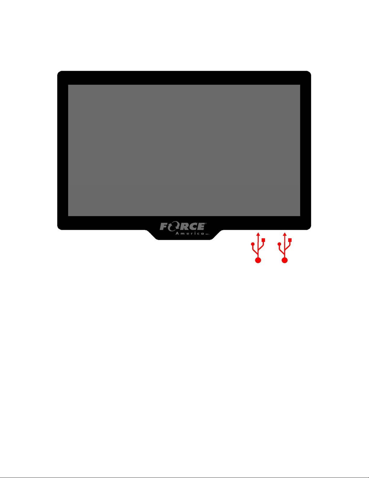
LCD Screen
The main system component of the 6100 is the 10” LCD touchscreen which displays operating
parameters, optional camera views and allows selection and adjustment of the various operating
modes.
It also features two USB ports on the lower right surface that can be used for system upgrades,
saving and loading calibration settings, as well driver identification. The locations of these are
shown by the red USB symbols.

2
Operator Interface
The Operator Interface provides controls for many functions of the SSC6100 control system. It is
designed to provide ergonomic and tactical controls while operating the vehicle. The specific
functions of the knobs, joystick, and pushbuttons for each operating mode are described in the
associated sections of this manual.
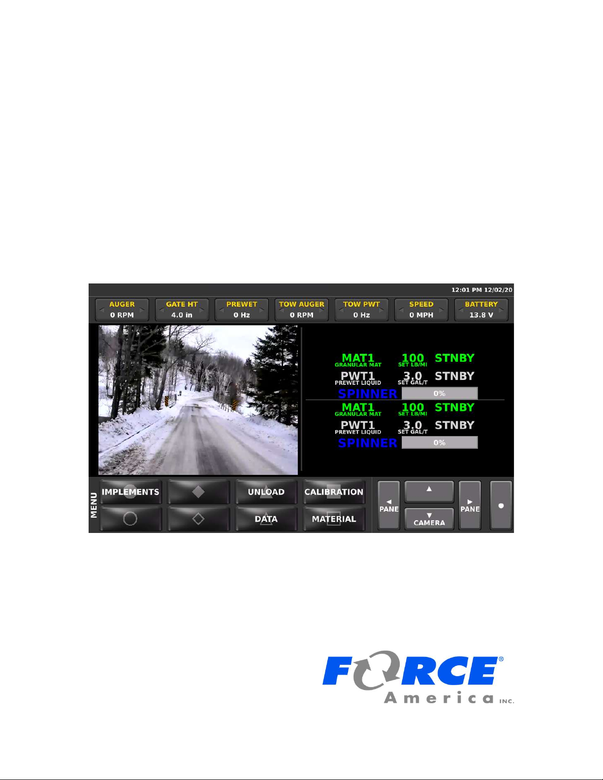
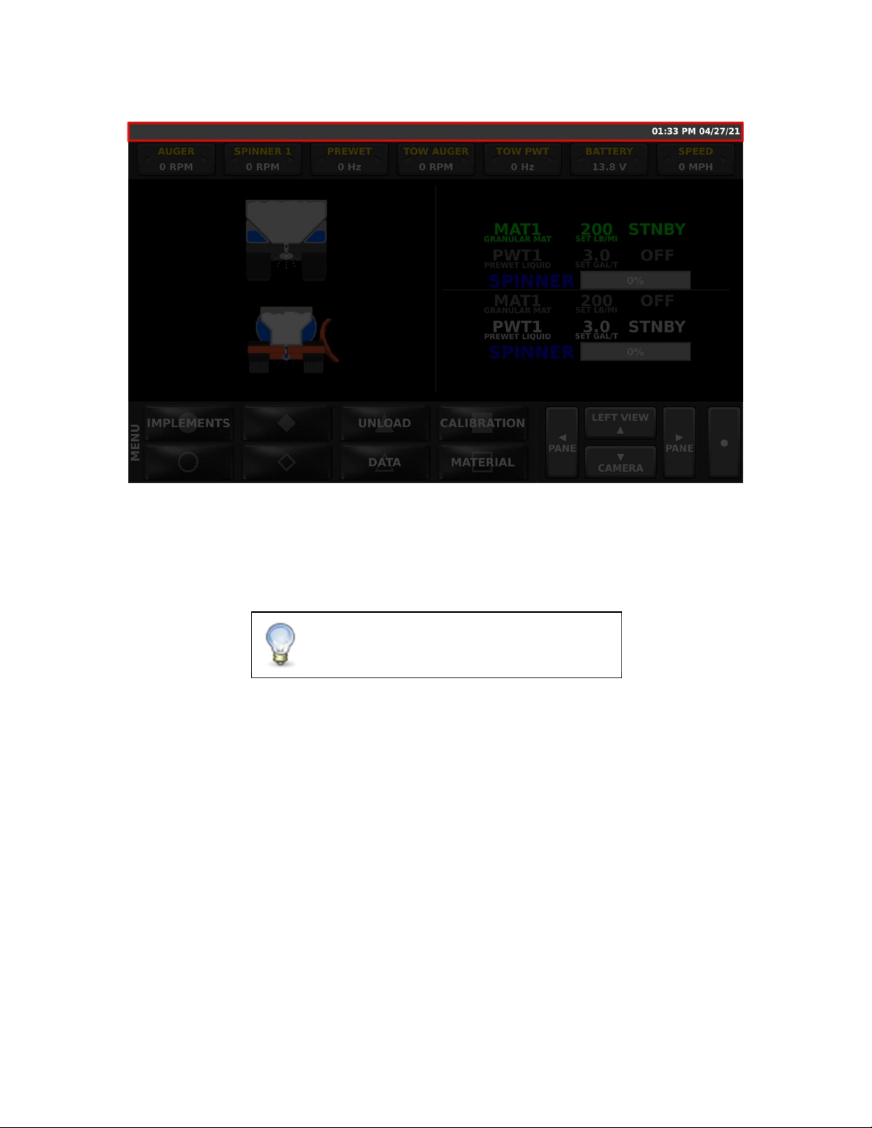
The Operation Screen
The Operation Screen is the main screen of the SSC6100, and provides controls for all of the
system functions as well as access to the Data, Calib, Unload, and Material Selection menus. It
is divided into six distinct areas described below.
3
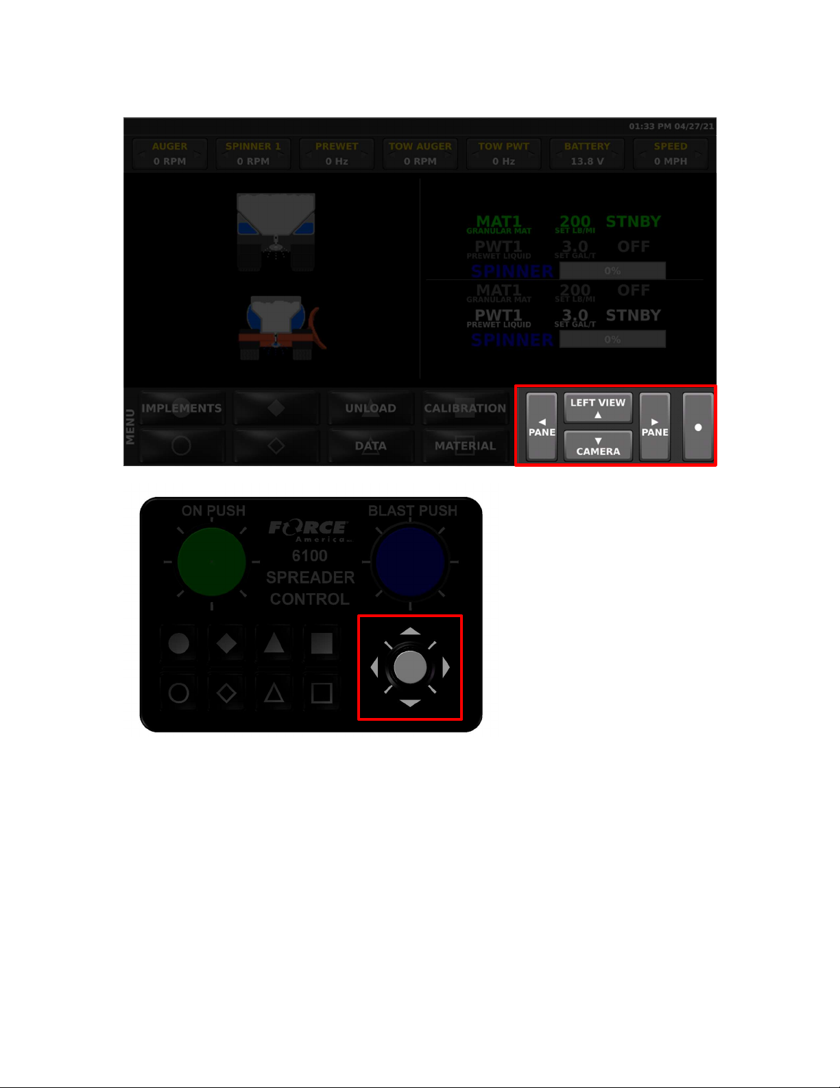
Navigation Controls
The touch screen navigation controls area and Nav Stick joystick provides a way to change
between views on the screen, select panes of Soft Switches, and make adjustments to settings.
The up, down, left, right, and select functions can be done using Nav Stick on the operator
interface or also with the touchscreen on the display.
4
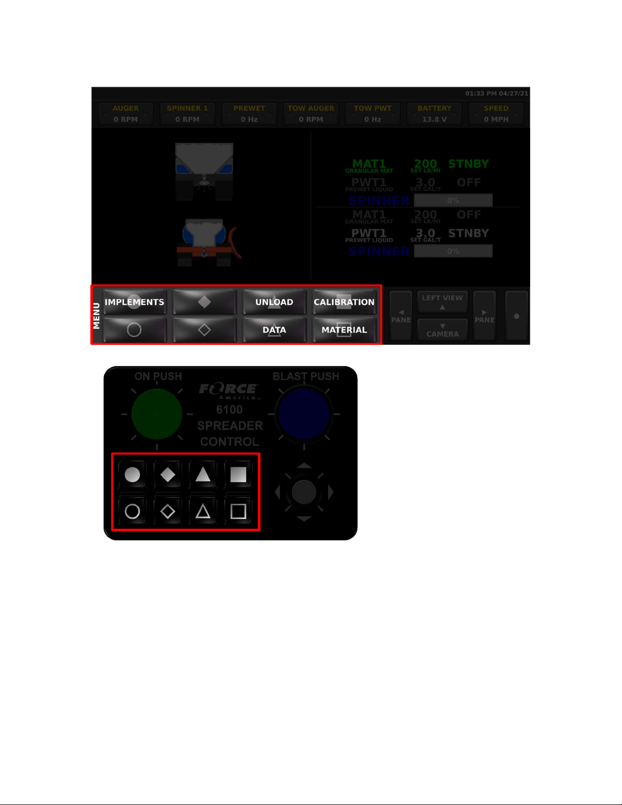
Soft Switch Panes
The touchscreen soft switch pane area and the associated buttons on the operator interface
provides access to an array of various switch functions. The name of the current pane is
displayed on the lower left corner of the screen.
The left and right navigational controls scroll between the available panes of Soft Switches. The
individual Soft Switches can be operated either by touching the Soft Switch button on the screen
or pressing the associated button on the operator interface. Soft Switches that toggle a function
Off and On indicate when the function is On by showing the button text in Green.
The number of and types of soft switch panes varies with each configuration of the system. Each
section of this manual will describe the function of each of the Soft Switches on their associated
switch pane(s).
5
Header Bar
The Header Bar appears across the top of the screen. System Time and Date will be displayed
on the right side of the Header Bar. The time is set automatically, including any Daylight Savings
Time changes your time zone supports.
The header bar also can show system status, warning, and error messages. If two or more
system status messages are active, the messages will sequence through each one.
For more information on specific warnings or
errors see Header Bar Errors and Warnings on
page 45.
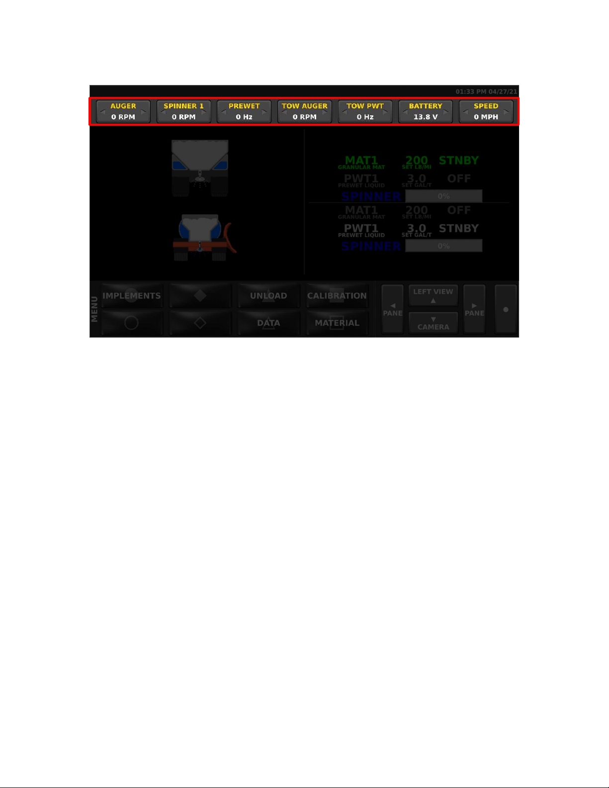
6
Data Items
Directly below the header bar is a row of data items that can be customized to show a number of
different types of information. Tap the left or right triangles to choose what information is
displayed on each item. For a list of all the available data items and their description, see
Appendix B - Data Items complete listing on page 55.

7
Left Window Area
The left window can display a variety of information depending on how the system is configured.
By default, it displays an image of the currently active spreader system on the vehicle. If enabled,
this window can also display road and air temperature, a joystick guide if applicable, and camera
images. Pressing up on the Nav Stick, or the up arrow on the Nav Stick Pushbutton will cycle
through the possible options for this window. Pressing down on the Nav Stick, or the down arrow
on the Nav Stick Pushbutton will cycle through camera images, if equipped.
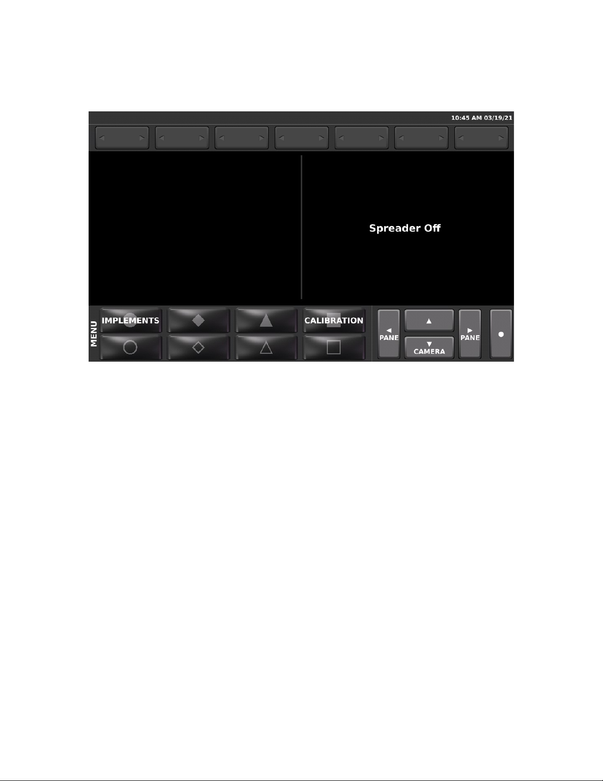
Right Window Area

8
The right window by default displays spreader rate information. If enabled, this window can also
display camera images. Pressing down on the Nav Stick Pushbutton, or the down arrow on the
Nav Stick will cycle through camera images, if equipped. If the spreader power switch is off, the
spreader screen with display “Spreader Off”.
Startup and Shutdown
Startup
The 6100 automatically powers up with the vehicle dash key ignition. As the system boots, it will
display a splash screen with a bar graph that tracks the boot progress until it is ready for
operation.
Driver ID
If Driver ID mode is enabled, the SSC6100 will require the user to log in before the system will
operate the spreader features. Joystick functions can still be operated without logging in.
Spreader material and usage data is recorded for the currently logged in driver. Be sure to use
the LOGOUT button on the MENU Softswitch pane when finished to ensure that all data is
recorded under the correct driver.
Three methods of identification are supported depending on which one has been selected in
Calibration.

9
Driver ID Key
This method requires a USB driver key to log in to the system. Insert a pre-programmed USB
Driver ID Key into either of the USB ports on the lower right side of the screen. Additional driver
ID keys can be programmed in the Calibration menu. See the SSC6100 Calibration manual for
more information.
Numeric Driver ID Entry
Alphanumeric Driver ID Entry
For the Numeric or Alphanumeric Driver ID modes, enter your numeric Driver ID using the on-
screen keypad and press the Enter button.
Pressing the ABC or 123 button toggles the entry screen between letters and numbers. The
Underscore button may also be used as part of the password text.

10
ESTOP
The SSC6100 has an emergency stop feature that is activated by pressing the red ESTOP
pushbutton located near the Operator Interface control. When ESTOP is activated the screen
shows the red Emergency Stop Activated message and a buzzer sounds. In addition, all outputs
are immediately shut off, the system enters Standby mode, and if the system is configured with a
Low Oil PTO or diverter valve, these will be shut off as well.
To cancel the ESTOP, rotate the red ESTOP pushbutton clockwise and let it pop back out. After
ESTOP mode is cleared, follow the ESTOP Cleared, System Reactivating warning message to
ensure that the vehicle is clear of personnel before pressing the Nav Stick to reactivate the
system outputs.
Shutdown
The 6100 automatically begins a shutdown process when power is no longer detected from the
key switch. A built-in timer prevents the system from shutting down during engine starting.
To reduce the risk of death or injury, ensure
that all personnel are clear from moving
machinery before activating outputs.
11
Pressing the Nav Stick Pushbutton will bypass the timer and immediately start the shutdown
process.
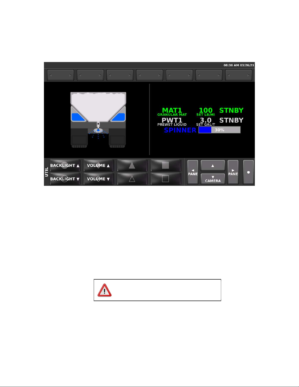
Backlighting and Speaker Volume
The intensity of the LCD backlighting and volume of the speaker can be adjusted on the UTIL
Soft Switch pane. As the speaker volume is adjusted, the speaker sounds a tone to show how
loud or soft the setting is.
Spreading Modes
Standby
Standby mode is generally used to start and stop the spreader at specific points on the route.
The SSC6100 system starts up in Standby mode with all the spreader outputs deactivated.
Pressing the Green knob on the Operator Interface toggles spreader in and out of Standby mode.
The Actual rates shown on the screen will read “STNBY” to indicate when the spreader is in
Standby mode. When the system is out of Standby and the vehicle is moving, the actual rates
will be displayed in this area.
Note that some menus and functions require that the 6100 to be in standby mode for them to be
accessed. Check to make sure the spreader is in Standby mode if you are having difficulty
accessing a certain function.
To reduce the risk of death or injury, ensure
that all personnel are clear from moving
machinery before activating outputs.
12
Blast
Blast is a spreader feature that is generally used to run the outputs at a higher than normal rate in
order to “Blast” a portion of road with extra material. Blast is activated by pressing the Blue knob.
Depending on the calibration settings, the blast mode may be set up to operate on a timer or
distance function that keeps the blast active for a certain amount of time or distance. The blast
mode in this case can be cancelled by pressing the Blue knob a second time.
When Blast is activated, the granular row will display the word “BLAST” instead of the material
name.
Note that activating blast while the vehicle is not moving will activate the outputs.
Loop Modes
The SSC6100 can apply most materials in one of three loop modes:
Closed-Loop Mode
Closed-Loop Mode is the default operating mode for spreading material. It uses the
vehicle speed and sensors on the material outputs to measure actual rates and apply
adjustments on the fly to increase material application accuracy. Outputs will
automatically start and stop with the vehicle.
Open-Loop Mode
Open-Loop Mode uses vehicle speed and a calculation to control the material outputs.
Because it doesn’t use a feedback sensor it is not as accurate as Closed Loop. Outputs
will automatically start and stop with the vehicle.
Manual Mode
Manual Mode does not vary its output rate with vehicle speed. Instead, granular or
prewet liquid material is applied at a constant rate. Materials spread in manual mode are
spread less accurately than in open-loop or closed-loop mode. Outputs do not start and
stop with the vehicle.
To reduce the risk of death or injury, ensure
that all personnel are clear from moving
machinery before activating outputs.
13
Operating Modes
Spreader On / Off
The 6100 system operates many aspects of the hydraulic system including joystick and spreader
functions. For off-season use where the spreader controls are not required, a Spreader Power
rocker switch can be used to remove the spreader functions from the operation screen and
prevent outputs from being activated.
This switch is located near the operator interface controls. When this spreader switch is off, the
operation screen appears as shown.
14
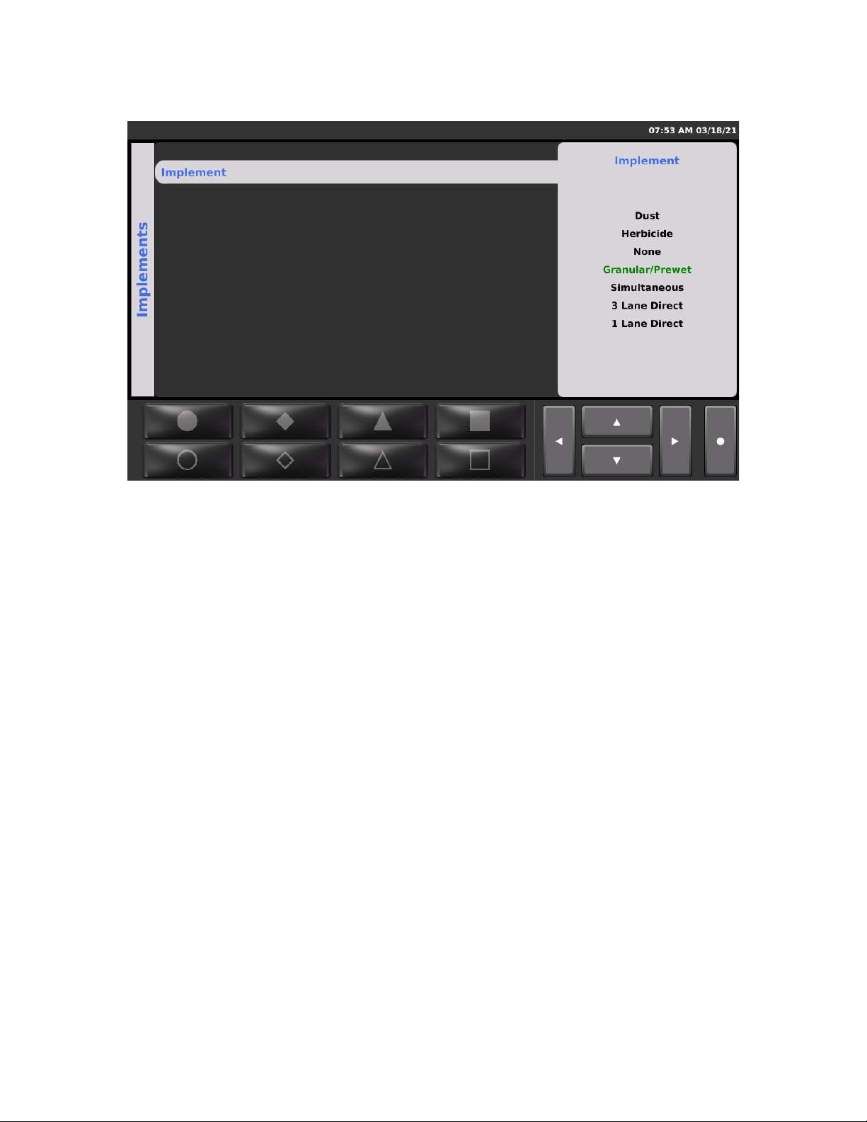
Implements
The SSC6100 system can optionally be configured to operate multiple types of equipment
allowing the vehicle to be tailored for spreading various materials or performing seasonal work.
These configurations are called Implements.
If your system supports multiple configurations there will be an Implements button on the MENU
Soft Switch pane. Press this button to choose between the available Implement configurations
using the Nav Stick controls
Note that the system must be in standby and the vehicle speed must be less than 5 MPH,
including Simspeed.
Each system is custom programmed at the factory to fit the specific needs of each vehicle. For
changes to the implements or how they behave, please contact a FORCE America
Representative for assistance.

15
Materials Menu
The Material Selection Menu allows you to choose between different materials for each of the
spreading modes. The list of available materials is configured and calibrated for each mode in
the Calibration settings.
To access the Materials Menu and make changes, scroll to the MENU Soft Switch pane and
press the Material Soft Switch. Use the Navigation Up and Down Controls to select a material
and press the Nav Stick to enter the menu.
Note that if the material you wish to select is not visible, exit the Material menu and select a
different Implement using the Implement menu.
Choose the desired material by name and press the Nav Stick button to select and activate that
material.
If temperature compensation mode is enabled, a Temperature Profile menu will allow selection
between one of three optional compensation profiles.
Exit the Material menu using the Navigation Control Left direction.
16
Spreading Modes
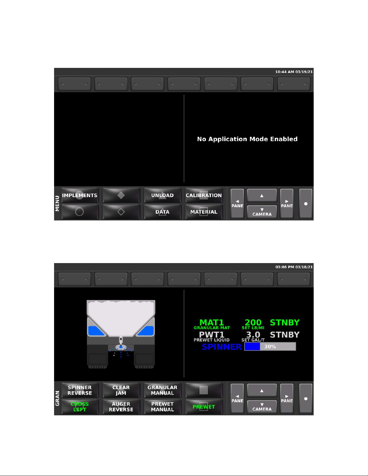
No Application Mode
Selecting an Implement type of “None” is generally used to disable seasonal functions and
prevent accidental activation of hydraulic functions. In this mode, the spreader functions will not
run, but Joystick functions will still operate normally.
Granular / Prewet Application Mode
This mode applies granular material with the option to apply prewet.

17
The green text contains information about the granular material, its set rate, and its actual output
rate. The granular rate is adjusted using the Green knob on the Operator Interface.
The white text contains information about your prewet material, its set rate, and its actual output
rate. The Prewet rate is adjusted by rotating the Nav Stick knob, if applicable. If the prewet
system is configured for gravity feed, no rates will be displayed. When the Prewet Soft Switch is
off, this line is grayed out and shows “OFF” for the actual rate.
The blue text and bar graph shows the relative spinner speed in percentage. The spinner speed
is adjusted using the Blue knob on the Operator Interface.
Granular and Prewet Soft Switches
The GRAN Soft Switch pane controls the granular functions. It may have additional options
available depending on how the system is configured. The following table describes each option.
SPINNER REVERSE Reverses the rotational direction of the spinner
CLEAR JAM Momentarily reverses the auger to attempt to clear a jam. The
auger reverses only for as long as the button is held.
GRANULAR MANUAL Toggles granular manual mode Off and On
CROSS LEFT / RIGHT Toggles between a left and right cross conveyor direction
AUGER REVERSE Toggles the direction of the auger to spread material in the
opposite direction.
PREWET MANUAL Toggles the Prewet manual mode material Off and On
PREWET Toggles the Prewet output Off and On
Adjustable Gate Mode
The granular system can be set up to use an adjustable gate mode. In this mode, the height of
the conveyor gate can be varied to cover a wider range of spreading rates. For accurate
spreading, it is important that the SSC6100 spreader control gate setting matches the actual
height of the gate.
Note that spreading with an incorrect gate heigh will result in inaccurate material rates and
inaccurate material usage data.
To remind users to check the gate height, a “Check Gate Setting” pop-up message box appears
whenever the material is changed. Press the Nav Stick pushbutton to clear the message box and
then use the Gate Height menu option to enter the correct gate height for the current gate setting
on the conveyor.
Two Position Gate Mode
For additional assurance that the correct gate height is set, the SSC6100 can be configured to
use a two position gate with sensors. In this mode, each material is set in calibration to use an
either “low” or “high” gate setting. When a material is selected, electrical sensors on the gate
confirm whether the gate is in the correct position. If it is in the wrong position for the selected
Other manuals for SSC6100 CAN ULTRA
4
Table of contents
Other Force America Control System manuals


 user manual")


