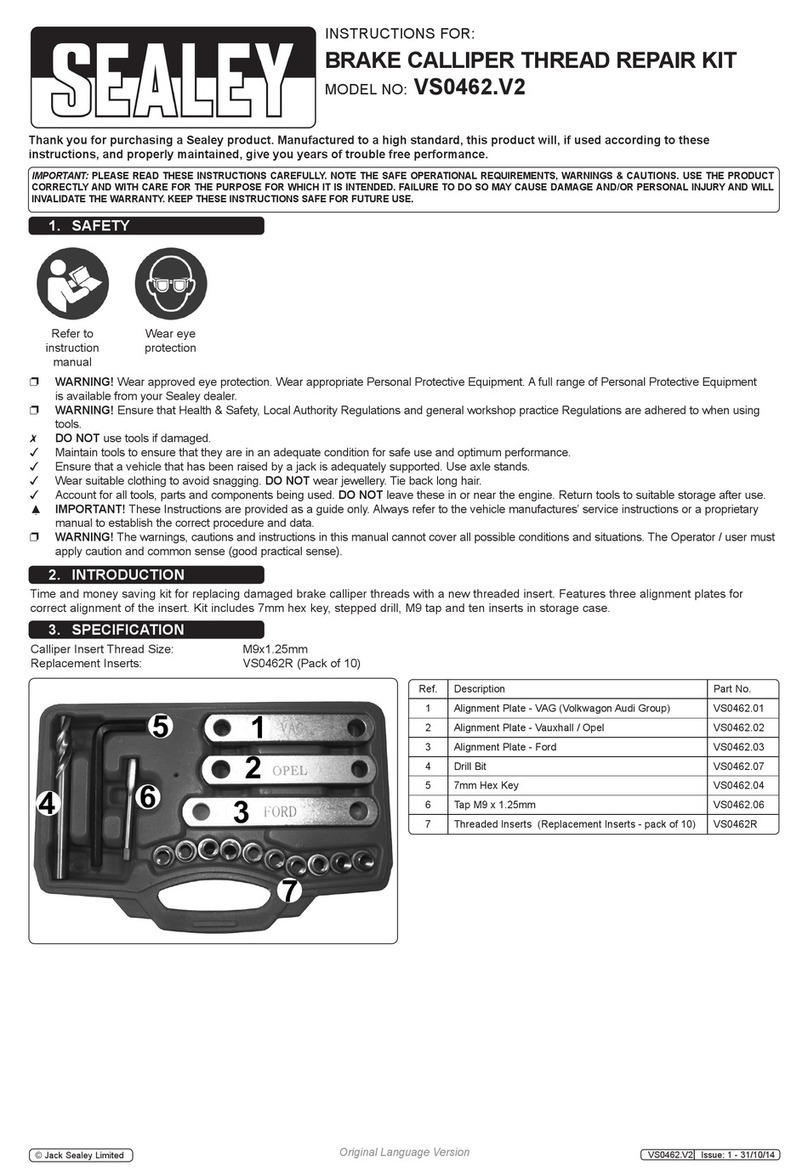
Black Hawk Automotive Wheel Dolly BH8075 Instructions for use

!ADVERTENCIA
• Leer, comprender, y seguir las instrucciónes antes de utilizar el aparato.
• El manual de instrucciónes y la información de seguridad deben estar comunicado en lengua del operador
antes del uso.
• No seguir estas indicaciónes puede causar daños personales o materiales.
Model Capacity
BH8075 1500 lb
SFA Companies
10939 N. Pomona Ave. Kansas City, MO 64153
Wheel Dolly
Operating Instructions & Parts Manual
Made in PRC
BH8075-M0 rev 12/07
Blackhawk Automotive is a Licensed Trade Mark Made by SFA Companies, Kansas City, MO
This is the safety alert symbol. It is used to alert you to potential personal injury hazards.
Obey all safety messages that follow this symbol to avoid possible injury or death.
!
Read this manual and follow all the Safety Rules and Operating Instructions before using this product.

2
Main Frame
Front Caster
Load Leveler
Chain
Handle
Support Strap
Hydraulic Unit
Figure 1 - Wheel Dolly Components
SAFETY and GENERAL INFORMATION
Save these instructions. For your safety, read, understand, and follow the information provided with and on this wheel
dolly before using. The owner and/or operator of this equipment shall have an understanding of this equipment and
safe operating procedures before attempting to use. The owner and/or operator shall be aware that use and repair
of this product may require special skills and knowledge. Instructions and safety information shall be conveyed in
the operator’s native language before use of this product is authorized. If any doubt exists as to the safe and proper
use of this wheel dolly, remove from service immediately.
Inspect before each use. Do not use if broken, bent, cracked, or damaged parts (including labels) are noted. Any
wheel dolly that appears damaged in any way, operates abnormally or is missing parts, shall be removed from service
immediately and the manufacturer notified. If you suspect that the product was subjected to a shock load (a load
dropped suddenly, unexpectedly upon it), immediately discontinue use until it has been checked by a factory authorized
service center (contact distributor or manufacturer for list of Authorized Service Centers). It is recommended that an
annual inspection be done by qualified personnel. Labels and owner’s manuals are available from manufacturer.
PRODUCT DESCRIPTION
Hydraulic wheel dolly is designed to facilitate the removal and installation of pneumatic tires and wheel assemblies
found on many trucks, buses and trailers. This is NOT suitable for use as a wheel and tire puller. It is designed ONLY
for use in removing up to rated capacity tire and wheel assemblies which are not bound and/or seized up at the brake
drum or hub assemblies. This device is designed to be used in conjunction with jacks and jack stands
NEVER load this device with more than the weight of the wheel assembly to be removed! ENSURE that the
vehicle is securely positioned and supported by mechanical means such as a pair of appropriately rated
jack stands or cribbing and blocking.
NEVER use a wheel dolly as a wheel pulling device. Before transporting wheel assembly ensure that it is
free from the hub or drum assembly and that it is secured to the wheel dolly using the provided securing means.
NEVER load this device with more than the weight of the wheel assembly to be removed!
!
!
Lifting Arms
Saddle Handle
Sleeve
Hydraulic Unit
Oil Filler
Plug
Handle
Release
Valve

3
Figure 2 - Assembly Illustration for Model BH8075
PREPARATION
Assembly (refer to Fig. 1 & 2)
1. Attach 3 1/2" caster (1) to left and right main frame (2 & 3) with bolts & washers (4).
2. Attach 5" caster (5) to rear support (6), with bolts, washers & nuts (7).
3. Insert left main frame (2) into right main frame (3).
4. Attach upright (8) and rear support (6) into the main frame assembly (2 & 3) with two bolts &
nuts (9) and four bolts, washers & nuts (10).
5. Attach support straps (11) to the mouting ears of upright and main frame with bolts, washers
and nuts (12).
6. Attach hydraulic unit (13) onto the upright assembly (8).
7. Insert load leveler handle (14) to rear support (6) with pin and cotter pin (15 & 16).
8. Attach the chain (17) onto upright assembly.
BEFORE USE
1. Verify that the product and the application are compatible, if in doubt call Blackhawk tech. service (816) 891-
6390.
2. Before using this product, read the operator's manual completely and familiarize yourself thoroughly with the
product, its components and recognize the potential hazards associated with its use.
3. To familiarize yourself with basic operation; position the hydraulic unit upright as shown in Fig. 1, engage the
release valve with the slotted portion of the provided handle, then turn the release valve:
a. Clockwise until firm resistance is felt to further turning. This is the ‘CLOSED’ release valve position used to
raise the load.
b. Counter-clockwise, but no more than 1 turn from the closed position. This is the ‘OPEN’ release valve position
used to lower the load.
4. With saddle fully lowered, remove the oil filler plug. Insert the handle into the handle sleeve; then pump 6 to 8
full strokes. This will help release any pressurized air which may be trapped within the reservoir. Check oil level.
Proper oil level is level with the oil filler plug hole. Adjust as needed, reinstall the oil filler plug.
5. Place the hydraulic unit to the wheel dolly as shown in Fig. 1. Position the hydraulic unit such that the saddle
mates with the provided indentation.
6. Check to ensure that wheel dolly rolls freely, that the pump and release valve operate smoothly. Raise and lower
the unloaded wheel dolly throughout the lifting range before putting into service. Replace worn or damaged parts
and assemblies with Factory Authorized Replacement Parts only.
13
17
14
16
9
15
6
5
7
12
4
Size of Hardware Kits Qty
3 bolt M8x16 8
lock washer
M8 8
7 bolt M8x16 4
lock washer M8 4
nut M8 4
9 bolt M12x100 2
nut M12 2
10 bolt M14x110 4
washer M14 4
nut M14 4
12 bolt M8x34 4
lock washer M8 4
nut M8 4
3
8
10
11
12

4
To avoid crushing and related injuries and or property damage:
• Read, understand and follow all printed materials provided with and on this wheel
dolly
• Do Not exceed rated capacity.
• Before positioning wheel dolly, ensure that the vehicle is securely positioned and
supported by mechanical means such as a pair of appropriately rated jack stands or
cribbing and blocking.
• Use only on smooth, hard and level surfaces capable of sustaining the load.
• Chock each unlifted wheel assembly in both directions.
• Be alert and sober when using this product! Never operate this equipment when
under the influence of drugs or alcohol.
• Before moving, lower the load to the lowest possible point and assure that the load
is centered and secured with a load restraint device.
• Only attachments and/or adapters supplied by the manufacturer shall be used.
• No alterations shall be made to this product.
• Never use hydraulic unit (jack) as a stand alone device.
• Apply load as close to the vertical position of the lifting member as possible.
!WARNING

5
OPERATION
Vehicle Preparation
1. Locate vehicle on a hard, level surface, such as reinforced concrete, large enough to accommodate vehicle, jacks,
jack stands, and wheel dolly.
2. Set the emergency brake unless the rear drum, tire and wheel are all to be removed as an assembly.
3. Chock all unlifted tires in both directions AND take every precaution necessary to ensure the set up is stable and
will prevent all inadvertent vehicle movement.
Raising The Lifting Arms
1. Close release valve by turning it with slotted portion of handle clockwise until firm resistance is felt to further
thread engagement.
Follow the vehicle manufacturers recommended removal and installation procedures for tire, wheel, hub,
or axle assemblies as needed! DO NOT remove more than is recommended by the vehicle manufacturer!
2. After the tire, wheel assembly has been loosened from the hub or axle and is ready to be removed, position the
dolly under the assembly to be removed. Pump until load reaches desired height. Adjust lift arm tilt such that the
tire, wheel assembly will nest securely between the lift arms without falling forward (toward the front wheels).
Loading the Wheel Dolly
NEVER load this device with more than the weight of the wheel assembly to be removed!
ENSURE that the vehicle is securely positioned and supported by mechanical means such as a pair of
appropriately rated jack stands or cribbing and blocking.
NEVER use a wheel dolly as a wheel pulling device. Before transporting wheel assembly. Ensure that it
is free from the hub or drum assembly and that it is secured to the wheel dolly using the provided restraint
device.
When the weight of the loosened tire, wheel assembly is supported by the wheel dolly, Carefully roll the wheel dolly
away from the drum or axle. When the assembly is clear, immediately secure the tire/wheel assembly with the
provided chains.
Lowering
1. Engage and slowly turn the release valve counterclockwise, but never more than 1 full turn.
Transporting Loaded Wheel Dolly
1. Ensure that wheel assembly is secured to the wheel dolly by means of the provided chains.
2. When wheel assembly has cleared the hub or the axle, lower the lift arms to the lowest position that will still allow
wheel dolly wheel and caster movement.
3. Push or pull to desired location.
Follow the vehicle manufacturers recommended removal and installation procedures for tire, wheel, hub,
or axle assemblies as needed!
If the operating handle is worn, operates abnormally, or will not positively engage the release valve,
immediately discontinue use of the jack until a replacement handle assembly can be acquired.
!
!
!
!
!
SPECIFICATIONS
Model Rated
Capacity
Lifting
Range
Hydraulic
Lift
Dimension
( L x W x H)
Lifting Arm
Dimension Tilt Range
BH8075 1500 lb. 2 1/4" ~ 11" 5" 43 1/2" x 43" x 34 7/8" 25 7/8" x 25 1/4" -2.5o~ 10o
This manual suits for next models
1
Table of contents
Other Black Hawk Automotive Tools manuals
