Black BLK-HD4E User manual

Quick Start Guide
Products: BLK-HD4E, BLK-HD4D, BLK-HD8D, BLK-HD10D, BLK-HD16D
BLK-HD4D (4 channels) and BLK-HD8D (8 channels)(upper)
BLK-HD10D (10-channel hybrid) and BLK-HD16D (16 channels)
PLEASE READ THIS GUIDE BEFORE USING YOUR RECORDER, and always follow
the instructions for safety and proper use. Save this guide for future reference.
BLK-HD4E, BLK-HDxxD_RQ
© 2013 Observint Technologies, Inc.
BLK-HD4E (4 channels)

Page 2
Specications*
BLK-HD4E BLK-HD4D BLK-HD8D BLK-HD10D BLK-HD16D
720p * 60 fps /
1080p * 28 fps
720p * 60 fps /
1080p * 28 fps
720p * 120 fps /
1080p * 62 fps
Analog: D1 realtime
HD: 720p * 60 fps /
1080p * 30 fps
720p * 240 fps /
1080p * 112 fps
Channels 4 channel 4 channel 8 channel 10 channels 16 channel
Input level
8 channels composite,
1.0 Vp-p, 75 Ω
2 channels HDcctv /
HD-SDI
HDcctv / HD-SDI
VGA
HDMI
HD-SDI - - - - 1 channel
LOOP ---8 channels -
BNC ---1 channels -
Spot --- 4 channels -
4 channel line input
1 channel line output
4 channel line input
1 channel line output
4 channel line input
1 channel line output
10 channel line input
1 channel line output
16 channel line input
1 channel line output
4 channels 4 channels 8 channels 10 channels 16 channels
1 alarm out 1 alarm out 2 alarm out 4 alarm out 4 alarm out
240F @ D1, half-D1, &
CIF
1280 x 720 60 fps 60 fps 120 fps 60 fps 240 fps
1920 x 1080 28 fps 28 fps 60 fps 30 fps 112 fps
Display
1, 4 1, 4 1, 4, 8 1. 4 1, 4, 8, 16
x1/4 ~ x32 x1/4 ~ x32 x1/4 ~ x16 x1/4 ~ x32 x1/4 ~ x8
Interface Type
Capacity of 1 HDD
Internal HDD No. 2 1 (2 in DVRs without
DVD-RW)
1 (2 in DVRs without
DVD-RW)
2 (4 in DVRs without
DVD-RW)
2 (4 in DVRs without
DVD-RW)
Serial ATA I
2TB (maximum)
1 HDMI, resolutions up to 1080p
G.711 (ADPCM)
H.264
QUADPLEX (Playback/Record/Network/Backup)
5 grades
Playback
Multi-Decoding
Playback speed
Search Mode
Storage HDD
Timeline, Event, Archive, Log
Pre Recording
Post Recording
Frame Rate ( /Sec)
Minimum 15 seconds, maximum 20 minutes
Minimum 10 seconds, maximum 60 seconds
Realtime
Recording Mode
Motion Detection
Recording by Channel Resolution
Continuous / Schedule / Motion/ Sensor/ Manual
Motion detection setup by grid
Yes
Record
Compression
Multi-Operation
Analog Resolution
HD Resoluti on
Recording Quality Grade
Audio Input / Output
Audio CODEC
Alarm Sensor Input (NC/NO selectable)
Alarm Output
ITEM
Recording performance
Video
Input
Output
HDcctv / HD-SDI
1 VGA, resolutions up to 1080p,

Page 3
*Specications and exterior design are subject to change without notice.
BLK-HD4E BLK-HD4D BLK-HD8D BLK-HD10D BLK-HD16D
USB ash drive
USB external HDD
Network
1 RS-485 1 RS-485 1 RS-485 2 RS-485 2 RS-485
1 1 1 2 2
640 x 360 x 120 fps
320 x 180 x 120 fps
640 x 360 x 120 fps
320 x 180 x 120 fps
640 x 360 x 240 fps
320 x 180 x 240 fps
1280 x 720 x 120 fps
640 x 360 x 120 fps
1280 x 720 x 240 fps
640 x 360 x 240 fps
Power
6.6 lb (3 kg) / 9.9 lb
(4.5 kg)
13.38” x 10.31” x 2.48”
(340 x 262 x 63 mm)
By Alarm, Motion, Video Loss, HDD error
USB ash drive, remote network
Yes
12 Vdc, 5 A
41 °F - 104 °F (5 °C ~ 40 °C)
0 - 90 % RH
Yes (free DDNS)
10/100/1000BASE-T Ethernet (RJ-45)
Live, Search, Backup, PTZF, Remote Setup, Remote Upgrade, Two Way Audio
Live, Search, PTZF, two way audio
Live, Search, Backup, PTZF, Remote Setup, Remote Upgrade, two way audio
1
2 (front 1, rear 1)
Video and still image
GUI
Weight / Gross weight 9 lb (4.1 kg) / 13.6 lb (6.2 kg) 15.0 lb(6.80 kg) / 19.8 lb (8.98 kg)
Dimension (w xh xd )
14.96” x 13.38” x 2.83”
(380 mm x 340 mm x 71.9 mm)
17.00” x 16.92” x 3.86”
(431.8 mm x 429.8 mm x 98.0 mm)
Power Supply Voltage 100~120 Vac / 200~240 Vac, 50/60 Hz, 280 W
Allowable Operating Temperature
Allowable Operating Humidity
Features
DLS (Day Light Saving)
Internal Beep
Firmware Upgrade
NTP
Yes
Network Streaming
Network
Access
Web Viewer (1:1)
3G Mobile Viewer (1:1)
Multi-sites monitoring SW (1:n)
Serial port
Console (RS-232C)
PTZ control
Termination
Network
Dynamic DNS
Network Interface
User I/F
Menu Display
Input Method Front panel buttons, remote control, mouse, keyboard
ITEM
eSATA
USB Port
Backup

Page 4
Product Components
The package contains the DVR unit and the components shown below.
DVR Unit
BLK-HD4D, BLK-HD8D
BLK-HD10D, BLK-HD16D
Client Software CD
Remote Control
Battery1.5V (AAA x 2EA)
Quick Guide
(User Guide as PDF on Client
Software CD)
Data Power Cable
Mounting Bracket & Screws
HDD Mounting Screws
Power Adaptor (DC12V 5A ) &
Power Cable (110V or 220V)
Mouse
BLK-HD4E

Page 5
BLK-HD4E
Front panel indicators and controls
Front Panel LEDs
No. Name Description
A HDD Indicates that the system is accessing the hard disk.
B POWER Indicating that the system is switched on.
Front Panel Buttons
No. Name Description
1
2
In playback mode, press to rewind the recording. Press again to increase the rewind speed.
3
Press to select an audio mode:
MUTE – Mute all 4 channels.
SINGLE - Highlighted channel only.
MIX - Mix all 4 channels.
4
Jump/step backward. In playback mode, the playback position moves 60 seconds backward.
5
In playback mode, press to fast forward the recording. Press again to increase the fast forward speed.
6
Press to enable/disable ALARM operation.
7
Jump/step forward. In playback mode, the playback position moves 60 seconds forward.
8
Press to start or stop manual recording.
In live display mode, press to open the SEARCH menu.
1 2,3 4,5 6 7 8,9
1011 12 13 14 15 16
17 18 1920
A B
9
In playback mode, press to play/pause the footage.

Page 6
No. Name Description
10
Press to open the SETUP menu.
11
Enable/disable the automatic sequence of display of channels in full screen, quad, 9-split display
mode.
12
Press to control Pan/Tilt/Zoom operations.
13
Press to capture video in jpeg format in live or playback mode.
14 (LEFT) Press to move left or to change the values in Setup mode. It is also used as the number 4 when
entering password.
15 (UP) Press to move up the menu in Setup mode. It is also used as the number 1 when entering password.
16 (RIGHT) Press to move right or to change the values in Setup mode. It is also used as the number 2 when
entering password.
17 (DOWN) Press to move down the menu in Setup mode. It is also used as the number 3 when entering
password.
18
Press to select desired menu item or to store the setup value.
19
Press for temporary storage of the changed value or to return to the previous menu screen.
20 USB port To save a snapshot image or video clip on a USB ash drive, or upgrade mware with a USB ash
drive, rst connect the USB ash drive to the USB port.

Page 7
BLK-HD4D, BLK-HD8D
Front panel indicators and controls
Front Panel LEDs
No. Name Description
A CH1~4, 8 Indicates that the channel is being recorded.
B HDD Indicates that the system is accessing the hard disk.
C ALARM Indicates that sensor(s) is/are triggered or motion is detected.
D NETWORK Indicates that a network client is connected
E BACKUP Indicates that a USB or DVD-RW device contains stored data
F POWER Indicating that the system is switched on.
Front Panel Buttons
No. Name Description
1
Channel keys. For channel10, press the 0 key. For channel 11, press the +10then the 1keys. For
channel 16, press the +10 then the 6 keys.
2
In playback mode, press to rewind the recording. Press again to increase the rewind speed.
3
Press to select an audio mode:
MUTE – Mute all 4 channels.
SINGLE - Highlighted channel only.
MIX - Mix all 4 channels.
4
Jump/step backward. In playback mode, the playback position moves 60 seconds backward.
5
In playback mode, press to fast forward the recording. Press again to increase the fast forward speed.
6
Press to enable/disable ALARM operation.
7
Jump/step forward. In playback mode, the playback position moves 60 seconds forward.
8
Press to start or stop manual recording.
9
In live display mode, press to open the SEARCH menu.

Page 8
No. Name Description
10
In playback mode, press to play/pause the footage.
11
Press to open the SETUP menu.
12
Enable/disable the automatic sequence of display of channels in full screen,quad, 9-split display
mode.
13
Press to control Pan/Tilt/Zoom operations.
14
Press to capture video in jpeg format in live or playback mode.
15 (LEFT) Press to move left or to change the values in Setup mode. It is also used as the number 4 when
entering password.
16 (UP) Press to move up the menu in Setup mode. It is also used as the number 1 when entering password.
17 (RIGHT) Press to move right or to change the values in Setup mode. It is also used as the number 2 when
entering password.
18 (DOWN) Press to move down the menu in Setup mode. It is also used as the number 3 when entering
password.
19
Press to select desired menu item or to store the setup value.
20
Press for temporary storage of the changed value or to return to the previous menu screen.
21 USB port To save a snapshot image or video clip on a USB ash drive, or upgrade rmware with a USB ash
drive, rst connect the USB ash drive to the USBport.
22 OPEN/CLOSE Press to open or close the disk tray.
23 DVD drive To save video, insert a CD-R/DVD-R
BLK-HD4E / BLK-HD4D back panel connectors
BLK-HD4D back panel connectors
No. NameDescription
1 Fan Airow outlet
2 HDCCTV / 1.0 INPUTS HD-SDI video inputs
3 AUDIO IN / AUDIO OUT 4 RCA connectors for audio input
1 RCA connector for audio output
4 HDMI HDMI video out.

Page 9
No. NameDescription
5 RS-232 interface Used for testing only.
6 VGA Connector for a VGA monitor.
7 eSATA port Connector for external storage
8 ETHERNET RJ-45 connector for LAN connection.
9 USB Use with a USB ash drive to archive still images and videos, and upgrade rmware, or use to
connect a USB mouse to the DVR
10 RS-485, sensor and alarm terminations RS-485 PTZ camera control terminals. Refer to the User Manual for more information.
11 POWER SOCKET Connect DC12V 5A power adaptor
BLK-HD8D back panel connectors
No. Name Description
1 HDCCTV 1.0 1 - 8 Inputs HD-SDI input
2 AUDIO IN / AUDIO OUT 8 RCA connectors for audio input, 1 RCA connector for audio output
3 RS-232 interface Used for testing only.
4 VGA Connector for a VGA monitor
5 HDMI HDMI video out
6 USB Use with a USB ash drive to archive still images and videos, and upgrade rmware, or use to connect
aUSB mouse to the DVR.
7 Sensor / alarm terminations See description below.
8 RS-485 RS-485 PTZ camera control terminal
9 ETHERNET RJ-45 connector for LAN connection
10 eSATA port Connector for external storage
11 POWER SOCKET Connect DC12V 5A power adaptor

Page 10
BLK-HD10D, BLK-HD16D
Front panel indicators and controls
Front Panel LEDs
No. NameDescription
A HDD Indicates that the system is accessing the hard disk.
B RECORD Indicates that the system is recording video.
C ALARM Indicates when a sensor is triggered or motion is detected.
D NETWORK Indicates that a network client is connected.
E BACKUP Indicates that a USB or DVD-R/W storage device is storing images or video.
Front Panel Buttons
Front Panel Buttons
No. Name Description
1 POWER Power ON/OFF
2 NUMBER Channel select keys. For channel “10”, press the “0” key. For channel “11”, press the “+10” key and the “1” key.
For channel “16”, press the “+10” key and the “6” key.
3 SEQ Enable/disable the automatic display of channels in full screen, quad, and 9-split screen mode.
4 PTZ Press to control pan/tilt/zoom operations.
5 SETUP Press to open the SETUP menu.
6 BACKUP Press to capture video in jpeg format during display during live or playback mode.
7 REW Press to rewind in playback mode.
8 F/REV Jump/step backwards. In playback mode, the jump moves 60 seconds back.
9 F/ADV Jump/step forwards. In playback mode, the jump moves 60 seconds forward.
10 FF Press to fast forward in playback mode.
11 REC Press to start or stop manual recording.
12 SEARCH
PLAY/PAUSE
During LIVE display mode, press to open the SEARCH menu.
During PLAYBACK mode, press to play or pause.
13 (UP) Press to move up the menu in SETUP mode. When entering a password, it inserts a 1.
14 (RIGHT) Press to move right or to change the values in SETUP mode. When entering a password, it inserts a 2.
15 (DOWN) Press to move down the menu in Setup mode. When entering a password, it inserts a 3.

Page 11
No. Name Description
16 (LEFT) Press to move left or to change the values in Setup mode. When entering a password, it inserts a 4.
17 SEL Press to select the highlighted menu item or store the setup value.
18 ESC Press for temporary storage of the changed value or to return to the previous menu screen.
19 USB Port Use with a USB flash drive to archive still images and videos and upgrade firmware, or use to connect a USB
mouse to the DVR.
BLK-HD10D back panel connectors
No. Name Description
1 VIDEO IN 8 BNC connectors for composite video input (NTSC/PAL) Channels 1 - 8
2 LOOP 8 BNC connectors for video output (loop back)
3 RS-485 1st and 2nd ports for RS-485 network (camera and controller)
4 SPOT 4 composite video outputs for spot monitoring
5 SENSOR IN 8 terminations for sensor device connection
6 AUDIO IN /
AUDIO OUT
8 connectors for audio input (channels 1 - 10)
1 connector for audio output
7 VIDEO IN 2 HD-SDI connectors for video input (channels 9. 10)
8 VGA Connector for a VGA monitor
9 HDMI OUT Main video out (1920 X 1080)
10 USB Use with a mouse or for backup
11 RS-232 Not used at this time
12 ALARM OUT 2 terminations for alarm device connection. Provides simple on/o switching with a relay (0.5 A / 125 Vac, 1 A / 30 Vac)
13 ETHERNET RJ-45 connector for LAN connection
14 eSATA port 2 eSATA ports for archive of still images or videoto an external HDD. Connector for external storage
15 RS-485 RS-485 A and B network termination switches ON/OFF
16 POWER SOCKET Connect 110 ~ 250 Vac power

Page 12
BLK-HD16D back panel connectors
No. Name Description
1 VIDEO IN HDCCTV 1.0 video input. Channels 1 - 8, 9 - 16.
2 AUDIO IN
AUDIO OUT
Audio input. Channels 1 - 4, 5 - 16
1 channel audio out
3 SENSOR IN Sensor in terminations
4 VIDEO OUT HDCCTV 1.0 video output
5 RS-232C For testing only
6 VGA Connector for a VGA monitor
7 HDMI HDMI video out
8 USB
9 RS-485 RS-485 termination for PTZ camera control
10 ETHERNET RJ-45 connector for LAN connection
11 eSATA port Connector for external storage
12 RS-485 RS-485 A and B network termination switches ON/OFF
13 POWER SOCKET Connect 110 ~ 250 Vac power
Remote Control
No. Name Description
1 ID When a remote control ID number is set in the DVR, input the DVR ID number.
2 REC To start and stop manual recording
3 Number To select channel (1, 2, .. 16) or to enter DVR ID number.
4 F/REW During playback - Tomovethe playback position 60 seconds backward.
During pause - To move the playback position 1 frame backward.

Page 13
No. Name Description
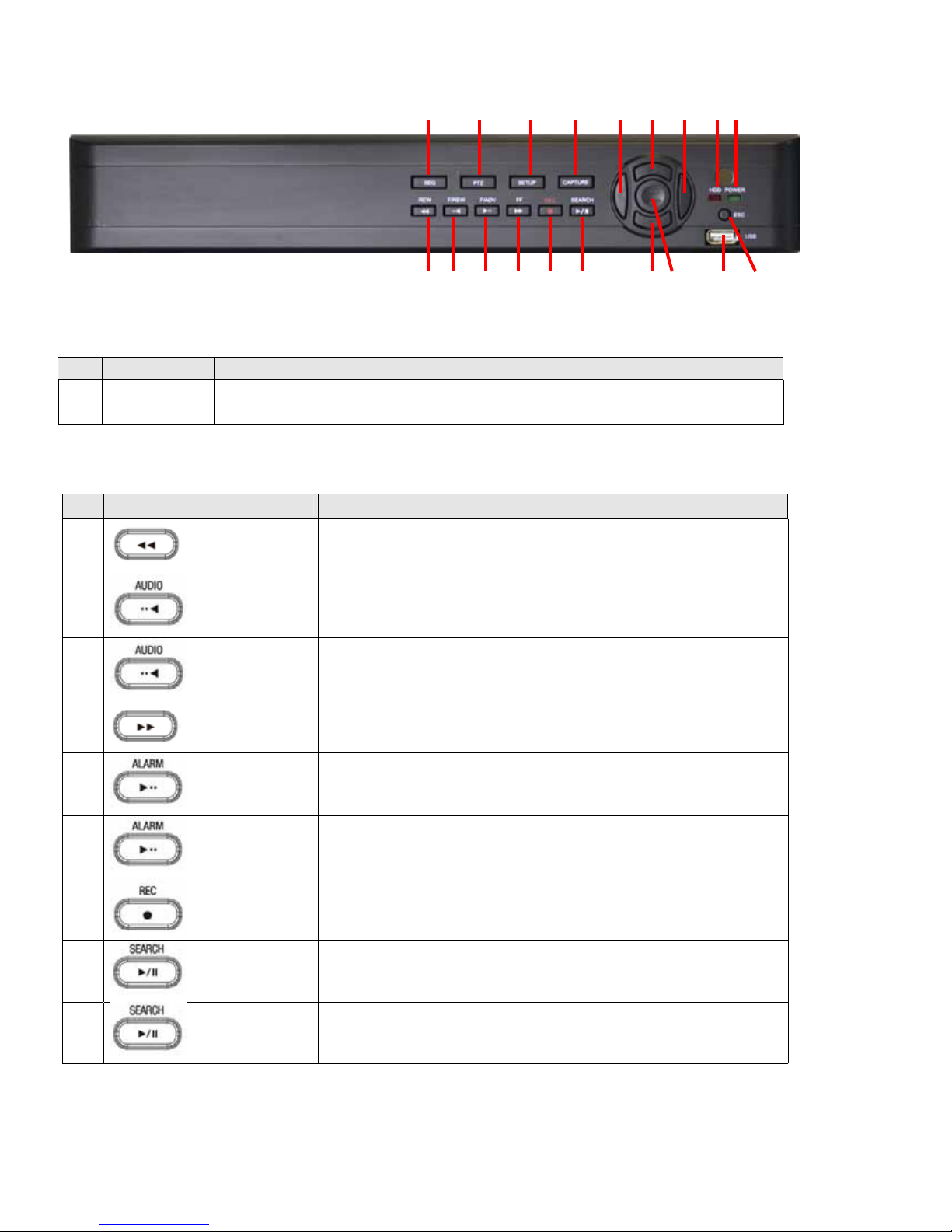
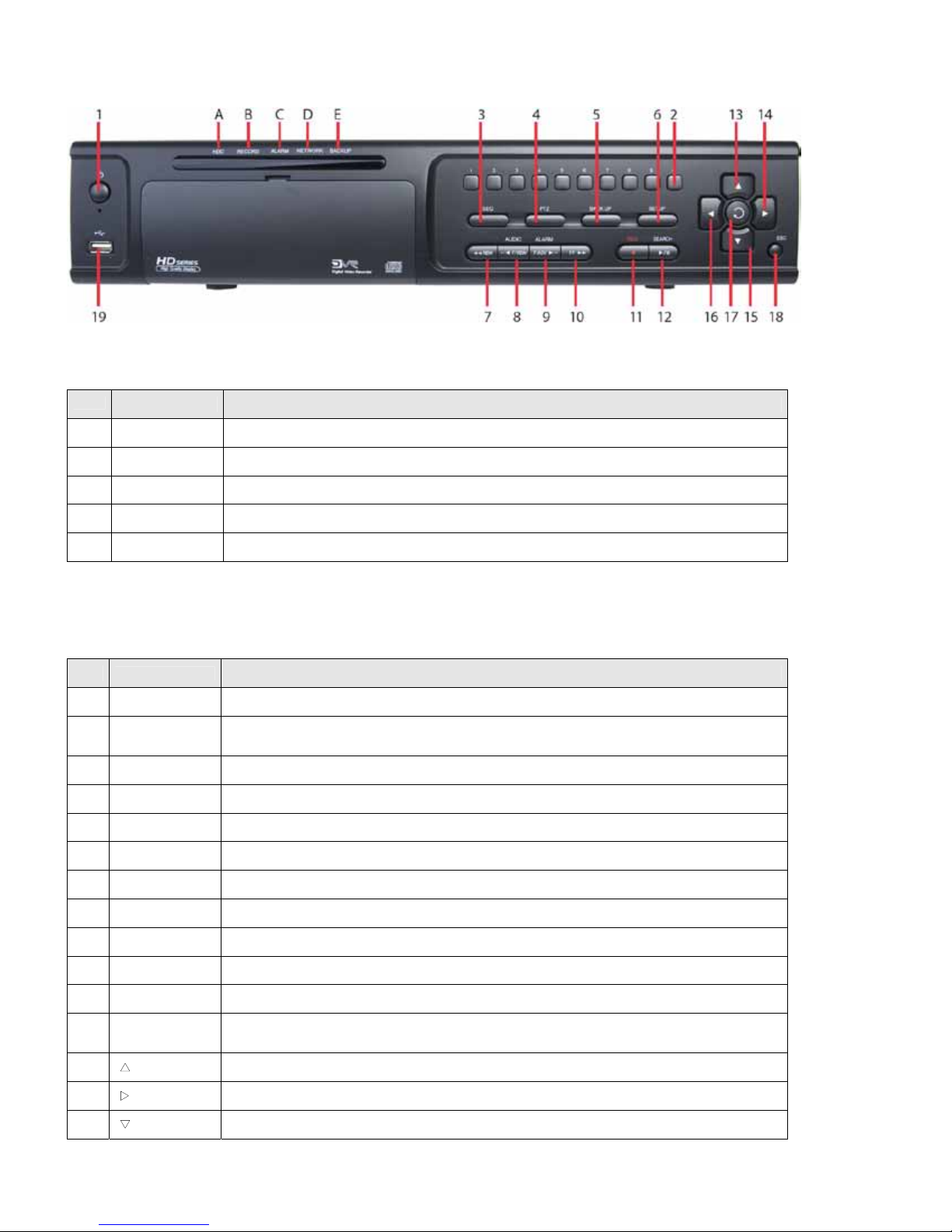
5 F/ADV During playback - Tomovethe playback position 60 seconds forward.
During pause - To movethe playback position 1 frame forward.
6 REW To rewind the recording. Press again to increase the rewind speed.
7 PLAY/PAUSE To play or to pause the footage in playback mode.
8 FF To fast forward the recording. Press again to increase the fast forward speed.
9 Control button Press to move the menu items or select channel.
10 SETUP To open the SETUP menu.
11 SEARCH To open the search menu.
12 ESC During setting - To return toprevious menu screen.During playback - To exit from playback System Lock – To lock a system
when pressing ESC button for 5 seconds. System Unlock – To unlock a system when pressing ESC button for 5 seconds.
13 BACKUP To start operations of backup in live or playback mode. (The same function button as CAPTURE on the front panel of DVR)
14 SEQ To start auto sequencing of the screen in full screen mode. (Toggle)
System Installation and Setup
Follow the steps below to install and setup your system. For more information, refer to the user manual provided on the CD.
1. Plan your entire installation carefully, considering:
Position of the cameras to eectively cover your surveillance targets. Avoid locations and orientations where bright
light might shine on or reect onto the camera lens.
Security of the camera and the cabling to the DVR. Is it easy for an intruder to disable the cameras?
Location of the DVR. Is it in a secure location? Is the temperature and humidity within specications?
2. Install your cameras in accordance with the manufacturer’s instructions.
3. Connect the video/audio and power extension cables to the cameras, then route them to the location of the DVR. Note
that video extension cables connectors are usually dierent at each end; the end with the male power connector attaches
to the camera drop cable, the end with the female power connector attaches to the power source and DVR.
4. Place the DVR on a clean, at surface. Do not apply power to the DVR at this time.
Plug the USB mouse to the USB port on the DVR.
Connect a monitor to the VGA or HDMI connector on the back of the DVR.
5. Connect the video extension cable from each camera to a video port on the back of your DVR.
If the camera location has a microphone, also attach the audio cable to an audio input connector on the back of the
DVR.
6. Attach the power extension cable to the cameras to the recommended power source to power them on.
7. Power on the DVR.
Connect the power adapter to the DC12V power connector on the back of the DVR.
Power on the monitor.
Connect the power cable to the power adapter and to a standard 120 VAC outlet. When the DVR is powering on, an
initialization window will appear.
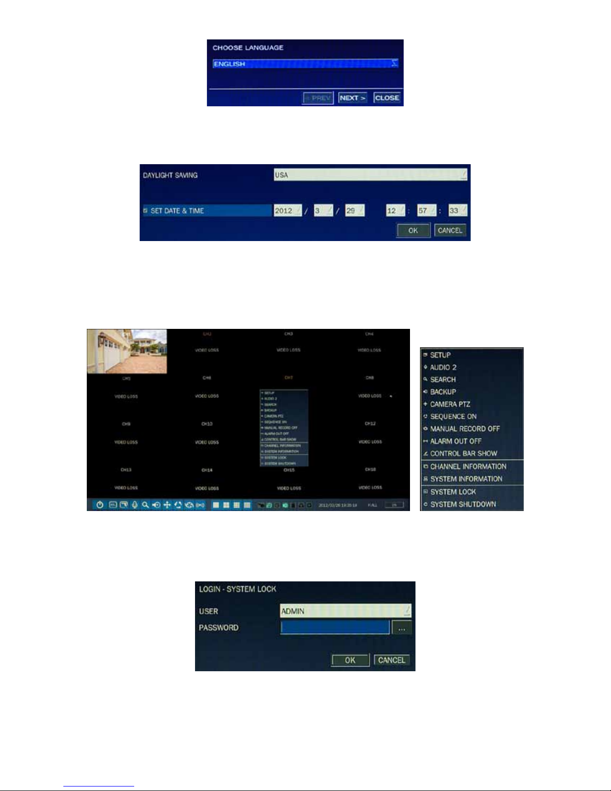
8. When the CHOOSE LANGUAGE window opens, use the mouse to open the dropdown list, select the language you prefer
to use, then click Next. NOTE: You can also change the language setting later through the SETUP menus.

Page 14
9. In the DAYLIGHT SAVING window, use the mouse to open the dropdown menus and select the DLS region, date and time.
When the correct date and time is shown, click Next. NOTE: The date and time setup in the DVR is used to timestamp
recorded video recordings. It is very important that this be set correctly if video recordings are used as evidence.
10. When the main screen opens, you should see a video image from each camera. Use this image to rene the manual
settings of the camera. These settings include the camera direction, and may include focus, zoom, and other settings.
11. Right click the mouse anywhere on the DVR screen then click SETUP, or press the SETUP button on the front panel to
access the SETUP menu.
If a LOGIN window opens, click the virtual keyboard button (at the right of the password entry eld) to open the keyboard
window. Use the keyboard to click in the default ADMIN password, “1111”, then click OK. In the LOGIN window, click OK
again to open the DVR SETUPmenus.
12. Congure the SETUP menus to customize the DVR settings for your system. Refer to the user manual included on the CD
for more information about DVR Setup and system conguration settings.

Page 15
Network Connections
LAN Connection – Using a crossover cable without a switching hub
Connect to the system directly using a crossover type network cable.
LAN Connection – Using a switching hub
Connect to the system using a hub (switching hub) and an Ethernet cable (10BASE-T/100BASE-TX CAT 5 LAN cable).

Page 16
Internet (ADSL) Connection
Connect to the system using a router or ADSL modem and an Ethernet cable (10BASE-T/100BASE-TX CAT 5 LAN cable).
Smartphone Access
When your DVR is congured for access across the Internet, you can remotely monitor and control
you video security using the free smartphone app Blackhawk. This app features:
View from 1 to 16 cameras
View images in portrait or landscape (single channel)
Monitor multiple locations
3G/Wi-Fi compatible
Playback Search
For more information, and to download and install the app, go to:
Apple®iPhone®, iPod touch®, or iPad®: http://itunes.apple.com/app/blackhawk-for-iphone/id422091119?
Android™ phones: http://www.androidzoom.com/android_applications/tools/blackhawk_tlcv.html
Other manuals for BLK-HD4E
1
This manual suits for next models
4
Table of contents
Other Black DVR manuals

Black
Black 4 Channel DVR User manual

Black
Black BLK-DH200400DH User manual

Black
Black BLK-DH200400DHDVD User manual

Black
Black BLK-DH200400D User manual

Black
Black BLK-HD4D User manual

Black
Black BLK-DH200400DH User manual

Black
Black BLK-DH200400DH User manual

Black
Black BLK-HD4E User manual

Black
Black BLK-SY10 Series User manual

Black
Black BLK-DH200400D User manual