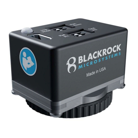
Blackrock Microsystems CerePlex m User manual

Manufacturer
630 Komas Drive | Suite 200
Salt Lake City | UT 84108 | USA
P +1 (801) 582-5533 | F +1 (801) 582-1509
www.blackrockmicro.com
Revision 5.00 / LB-0729 – CerePlex µ IFU – 2020/08
© 2020 Blackrock Microsystems, LLC
CerePlex µ
Instructions for Use

Revision 5.00 / LB-0729 – CerePlex µ IFU
© 2020 Blackrock Microsystems, LLC
2
Table of Contents
Warnings and Precautions .................................................... 3
Warnings ........................................................................................ 3
Precautions ..................................................................................... 3
Specifications ........................................................................ 4
What This Manual Covers ..................................................... 6
Hardware ............................................................................... 7
Blackrock CerePlex µ 32 Headstage Pin-out .................................. 7
Blackrock CerePlex µ 16 Headstage Pin-out .................................. 7
CerePlex µ Headstage LED ............................................................ 8
CerePlex µ Headstage Motion Sensing .......................................... 8
CerePlex µ Headstage Adaptor ...................................................... 9
Motion Sense Switch .................................................................. 10
LED Switch ................................................................................ 10
Impedance Switch ...................................................................... 10
CerePlex µ Headstage Cabling .................................................. 10
Instructions for Assembly .................................................... 11
Cleaning, Maintenance, and Disposal................................. 11
Cleaning ....................................................................................... 11
Maintenance ................................................................................. 11
Disposal ........................................................................................ 11
Magnetic Resonance .......................................................... 11
Troubleshooting .................................................................. 12
Warranty .............................................................................. 13
Return Merchandise Authorization (RMA) .......................... 13
Support ................................................................................ 14
Complaints .................................................................................... 14

Revision 5.00 / LB-0729 – CerePlex µ IFU
© 2020 Blackrock Microsystems, LLC
3
Warnings and Precautions
Warnings
Do not touch any exposed electrical conductors when the CerePlex µ
connector is attached to devices on subject’s head as this may result in
inducing electric charge to the neural tissue. Irreversible damage may
occur.
Do not use the CerePlex µ in the presence of flammable anesthetic
agents or any other reagents.
Avoid strong static discharges from sources like television or computer
monitors because they can damage the electrical components of the
system.
Keep the CerePlex µ away from liquids. Contact with water, shower
spray, or wet surfaces can lead to the subject receiving an electrical
shock.
Connection of external instruments to the CerePlex µ may compromise
electrical safety.
Always use antistatic or electrostatic discharge (ESD) safe gloves when
connecting the CerePlex µ.
Use only the supplied Blackrock Microsystems components (Cerebus™
system & Digital Hub128 or CerePlex Direct, CerePlex µ Cable).
Substitution of components not supplied by Blackrock Microsystems may
affect system performance and subject safety.
Use caution when placing cables and other connectors to minimize the
likelihood of tripping or accidentally pulling on cables. Pulled cables may
cause damage to the CerePlex µ or any other connected devices.
Precautions
Read this entire manual prior to using the device.

Revision 5.00 / LB-0729 – CerePlex µ IFU
© 2020 Blackrock Microsystems, LLC
4
Specifications
Model Name
Blackrock CerePlex µ
32
-
Channel PN
-
9714
Power Requirements
+5 VDC, 70 mA maximum load
Resolution
16-bit ADC. 250 nV/bit
Sampling Frequency
30 kHz
Mode of Operation
Continuous
Input Frequency Range
0.3 Hz – 7.5 kHz
Input Impedance Range
1300 MΩ @ 10 Hz, 13 MΩ @ 1 kHz
Maximum Input Voltage
± 8.169 mV with respect to reference
Ingress Protection
Ordinary Equipment, not fluid resistant, IP20
Operating Environment
10˚C to 40˚C, 5 to 95% R.H. (non-condensing)
Storage Environment
-20˚C to 50˚C, 5 to 100% R.H. (non-condensing)
Input
Connector
36-pin Omnetics part number A79023-001
Headstage Weight (without cable)
1.2g
Headstage Dimension
s
13 mm x 20 mm

Revision 5.00 / LB-0729 – CerePlex µ IFU
© 2020 Blackrock Microsystems, LLC
5
Model Name
Blackrock CerePlex µ 16
-
Channel PN
-
9162
Power Requirements
+5 VDC, 70 mA maximum load
Resolution
16-bit ADC. 250 nV/bit
Sampling Frequency
30 kHz
Mode of Operation
Continuous
Input Frequency Range
0.3 Hz – 7.5 kHz
In
put Impedance Range
1300 MΩ @ 10 Hz, 13 MΩ @ 1 kHz
Maximum Input Voltage
± 8.169 mV with respect to reference
Ingress Protection
Ordinary Equipment, not fluid resistant, IP20
Operating Environment
10˚C to 40˚C, 5 to 95% R.H. (non-condensing)
Storage Environment
-20˚C to 50˚C, 5 to 100% R.H. (non-condensing)
Input Connector
18-pin Omnetics part number A79015-001
Headstage Weight (without cable)
1g
Headstage Dimensions
13 mm x 20 mm

Revision 5.00 / LB-0729 – CerePlex µ IFU
© 2020 Blackrock Microsystems, LLC
6
What This Manual Covers
The Blackrock CerePlex µ provides an interface between the Cerebus recording system
or the CerePlex Direct recording system for high fidelity transmission and recording of
extracellular spikes and local field potentials from the brain. The Blackrock CerePlex µ
converts analog signals to digital format right at the recording site which dramatically
reduces the noise introduced to the signal during transmission. Moreover, the motion
sensor on the CerePlex µ provides 3-axis accelerometer and 3-axis gyroscope at the
headstage.

Revision 5.00 / LB-0729 – CerePlex µ IFU
© 2020 Blackrock Microsystems, LLC
7
Hardware
Blackrock CerePlex µ 32 Headstage Pin-out
Blackrock CerePlex µ 16 Headstage Pin-out
Figure 3-1–Top, CerePlex µ Input Connector Pin-Out. Be sure to note the side of the
headstage that has the Omnetics date code to ensure the correct orientation.

Revision 5.00 / LB-0729 – CerePlex µ IFU
© 2020 Blackrock Microsystems, LLC
8
CerePlex µ Headstage LED
Two infrared LEDs on the headstage can be used for video tracking using
Blackrock’s Neuromotive video tracking system. The LEDs can be turned on or
off via the CerePlex µ Headstage Adaptor (see below).
CerePlex µ Headstage Motion Sensing
The motion sensing can be turned on and off via the HDMI adaptor. The
CerePlex µ 32-Channel will occupy two 32-channel banks in Central when the
Motion Sense Switch is ON; however, only the first 7 channels of the second
bank will be occupied. For instance, if CerePlex µ is recording neural signal data
on channels 1 to 32, channels 33-37 will contain the motion data when the When
the Motion Sense Switch is OFF, the CerePlex µ 32-Channel will only occupy
one 32-channel bank. The CerePlex µ 16-Channel will always occupy one 32-
channel bank in Central regardless of the position of the Motion Sense Switch.
Refer to the table in Figure 3-3 for the motion data channel mapping and the axis
orientations of each sensor.
The table in Figure 3-3 shows the full-scale range for the motion sensors to allow
conversion to the appropriate units. As with the neural data, motion data is saved
to a file as 16-bit signed integers. When reading the file, multiply the
accelerometer channels by 1.22 x 10⁻⁴ to convert the 16-bit integers to g, and
the gyroscope channels by 0.0305 to convert the 16-bit integers to °/s.
Figure 3
-
2
–
CereP
lex µ LED location
Figure 3-3–Motion sensor axis orientations, channel mapping, and conversion
factors

Revision 5.00 / LB-0729 – CerePlex µ IFU
© 2020 Blackrock Microsystems, LLC
9
Sensor Axis
Channels in Central
µ 32
Channels in Central
µ 16
Full
-
scale Range
Accelerometer X
34
18
± 4 g
Accelerometer Y
35
19
± 4 g
Accelerometer Z
33
17
± 4 g
Gyroscope X
38
22
± 1000 °/s
Gyroscope Y
39
23
± 1000 °/s
Gyroscope Z
37
21
± 1000 °/s
CerePlex µ Headstage Adaptor
The CerePlex µ headstage adaptor provides a simple and easy way to control
the headstage. The three switches on the adaptor allow the user to control the
LED on/off, motion sensing on/off, and impedance on/off. See Figure 3-4 for
switch locations.
Figure 3-4–CerePlex µ Adaptor Switch Setup. | = ON position; O = OFF position.

Revision 5.00 / LB-0729 – CerePlex µ IFU
© 2020 Blackrock Microsystems, LLC
10
Motion Sense Switch
The switch is located at the side of the adaptor and sends motion data
when the switch is in the ON position
LED Switch
The two IR LEDs on the headstage will illuminate when this switch is in
the ON position.
Impedance Switch
To select impedance mode, toggle the switch to the ON position. The
CerePlex µ headstage should not be in Impedance mode while
attempting to record neural signals. In Impedance mode, the CerePlex µ
delivers to each electrode sequentially a 1 kHz, 1 nA peak-to-peak
current for 100 ms. The CerePlex µ impedance measurements are
accurate for electrodes between 10 kOhm and 2 MOhm.
In order to measure electrode impedances with the CerePlex µ the
Central software must be configured to measure impedances using
CerePlex Family headstages. This is only required once, unless the
setting is subsequently changed. In the Central software, click on the
TOOLS drop down box then select OPTIONS. Under Auto Impedance
Interface, select “CerePlex Family”. Click OK. Next, click on the
IMPEDANCE TESTER button. Populate the dialog box that appears on
the screen if desired. Impedance values should be displayed on the
screen. To exit impedance mode, close the Impedance Tester window,
toggle the switch to OFF.
CerePlex µ Headstage Cabling
Cables are available in 1.5 ft and 2.5 ft lengths. Multiple cables can be
daisy chained to create longer cable lengths. Note that, both connectors
on the cable are keyed. Align the connectors before making connections
to avoid damage to the pins.

Revision 5.00 / LB-0729 – CerePlex µ IFU
© 2020 Blackrock Microsystems, LLC
11
Instructions for Assembly
1. If using a Cerebus recording system, turn off the power on the Digital Hub 128
before connecting. If using a CerePlex Direct, turn off the power before
connecting.
2. Plug the input connector on the CerePlex µ into the connector attached to the
electrodes or signal simulator.
3. Connect the cable to the CerePlex µ and the CerePlex µ adaptor.
4. Plug the HDMI connector on the adaptor to the connector on the back of the
Digital Hub 128, or the front of the CerePlex Direct.
5. Make sure the connections are secured.
6. Turn on the power of the Digital Hub 128 or the CerePlex Direct.
7. After recording, turn off the Digital Hub 128 or CerePlex Direct before any
disconnection.
Cleaning, Maintenance, and Disposal
Cleaning
The CerePlex µ may be cleaning with isopropyl alcohol (70%). Do not apply
pressure to the circuit board or you may damage it. Let dry completely before
use.
Maintenance
The CerePlex µ does not require maintenance.
Disposal
All devices, both used and unused, should not be disposed with household
waste. Return to a recycling point for electric and electronic devices.
Magnetic Resonance
The CerePlex µ has not been evaluated for safety and compatibility in the MR
environment. The CerePlex µ has not been tested for heating, migration, or image
artifact in the MR environment.

Revision 5.00 / LB-0729 – CerePlex µ IFU
© 2020 Blackrock Microsystems, LLC
12
Troubleshooting
Problem Symptom Failure Potential fix
Poor Signal to
Noise Ratio /
Noisy Signal
A typical high-passed
noise band is less than
+/- 30 microvolts or
approximately 60
microvolts peak to
peak (roughly 10 root
mean squared). If the
signal that you are
receiving is noisier than
this, it could be due to
a number of factors
Poor contact
between device
electrode connector
Electrode connections:
Ensure the electrode
has good ground
contact with the
subject. Check that the
reference wires are
exposed to tissue
Motion data is
not being
continuously
transmitted to
Central
Moving the headstage
does not create any
varying signal on
channels 17–23 for the
16-channel µ or on
channels 33–39 for the
32-channel µ
The HDMI adapter is
not transmitting
motion data from the
µ’s onboard
accelerometer to the
Direct or Digital Hub
Make sure the Motion
Sense Switch is in the
ON position. You can
also try unplugging the
HDMI Adapter from the
CerePlex Direct or the
Digital Hub, and
plugging it back in
Motion data comes
through intermittently
The µ cable’s wire
carrying motion data
has become
compromised
Switch out the µ cable
if one is available
Non-Green
Light on Digital
Hub Bank
The indicator light on
the Digital Hub for the
bank that the CerePlex
µ is attached to should
be green.
If it is not green, it
could mean that
your device is
damaged or
malfunctioning or it
could mean that you
are using an
unapproved or
damaged digital
data cable between
the Digital Hub and
the CerePlex µ
Try changing the cable
to a Blackrock
approved cable
It could also mean
that the Digital Hub
is malfunctioning
Try changing which
bank that the CerePlex
µ is connected to. If the
problem persists,
contact Blackrock
Support for assistance

Revision 5.00 / LB-0729 – CerePlex µ IFU
© 2020 Blackrock Microsystems, LLC
13
Warranty
Blackrock Microsystems (“Blackrock”) warrants its products are free from defects in
materials and manufacturing for a period of one year from the date of shipment. At its
option, Blackrock will repair or replace any product that does not comply with this
warranty. This warranty is voided by: (1) any modification or attempted modification to
the product done by anyone other than an authorized Blackrock employee; (2) any
abuse, negligent handling or misapplication of the product; or (3) any sale or other
transfer of the product by the original purchaser.
Except for the warranty set forth in the preceding paragraph, Blackrock provides no
warranties of any kind, either express or implied, by fact or law, and hereby disclaims all
other warranties, including without limitation the implied warranties of merchantability,
fitness for a particular purpose, and non-infringement of third-party patent or other
intellectual property rights.
Blackrock shall not be liable for special, indirect, incidental, punitive, exemplary or
consequential damages (including without limitation, damages resulting from loss of use,
loss of profits, interruption or loss of business or other economic loss) arising out of non-
compliance with any warranty. Blackrock’s entire liability shall be limited to providing the
remedy set forth in the previous paragraph.
Return Merchandise Authorization
(RMA)
In the unlikely event that your CerePlex µ needs to be returned to Blackrock for repair or
maintenance, do not send any equipment back without a Return Merchandise
Authorization Number. An RMA number will be issued to you by a Blackrock
representative. If you need to obtain an RMA number, you may contact a product
support representative at +1 (801) 582-5533 or by emailing
support@blackrockmicro.com.
Once an RMA number has been issued, it is important to safely pack the returned item
for shipping back to Blackrock. It is preferred that you save the original boxes and
packing materials that your system arrived in for return shipment. Please address the
package as follows:
Blackrock Microsystems, LLC
ATTN: RMA#
630 S. Komas Dr., Suite 200
Salt Lake City, UT 84108 USA
Tel: +1 (801) 582-5533

Revision 5.00 / LB-0729 – CerePlex µ IFU
© 2020 Blackrock Microsystems, LLC
14
Support
Blackrock prides itself in its customer support. For additional information on this product
or any of our products, you can contact our Support team through the contact
information below:
Manuals, Software Downloads, and Application Notes
www.blackrockmicro.com/technical-support
Complaints
When filing a complaint, please provide the product description, product number,
software version, lot number, complainant's name and address, and the nature of
the complaint.
Issues or Questions
www.blackrockmicro.com/technical-support
support@blackrockmicro.com
U.S.: +1 (801) 582-5533
The CerePlex µ is not for use on human subjects.
Table of contents
Other Blackrock Microsystems Control Unit manuals
Popular Control Unit manuals by other brands
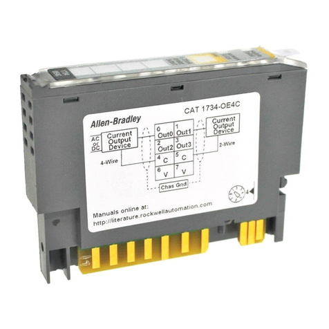
Rockwell Automation
Rockwell Automation 1734-OE4C installation instructions
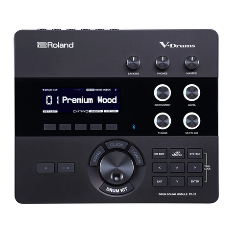
V Expressions
V Expressions Roland TD-27 quick start guide
Force Computers
Force Computers SYS68K/CPU-40 user manual
K1EL
K1EL Morse Tutor Board user manual
BENDIX
BENDIX PP-7 TRAILER SUPPLY VALVE manual
VECTOR CONTROLS
VECTOR CONTROLS TRI2 Series Operation manual
