manuals.online logo
Brands
  1. Home
  2. •
  3. Brands
  4. •
  5. GMI
  6. •
  7. Control Unit
  8. •
  9. GMI TB-D5001 User manual

GMI TB-D5001 User manual

Characteristics: Technical Data:
Features:
Ordering Information:
Image:
TB-D5001
HRT-003
Supply:
24 Vdc nom (20 to 30 Vdc) reverse polarity protected, redundant terminal blocks,
OR diodes to select higher supply source.
Connection: by polarized plug-in disconnect screw terminal blocks to accommodate
terminations up to 2.5 mm2.
2 LEDs indication: green.
Protection fuse: 2 A time lag (spare fuse provided on Termination Board).
HART®interface:
Connection: 4 flat cable 34 poles male connectors (requires female mating connector).
DC Isolation: dual capacitor for each channel.
Common mode voltage: up to 50 V.
Additional TBs interface:
Connection: 2 flat cable 10 poles male connectors (requires female mating connector).
Compatibility:
CE mark compliant, conforms to Directives:
2014/34/EU ATEX, 2014/30/EU EMC, 2014/35/EU LVD, 2011/65/EU RoHS.
Environmental conditions:
Operating: temperature limits – 40 to + 70 °C, relative humidity 95 %, up to 55 °C.
Storage: temperature limits – 45 to + 80 °C.
Safety Description:
ATEX: II 3G Ex nA IIC T4 Gc
IECEx : II 3G Ex nA IIC T4 Gc
non-sparking electrical equipment.
Approvals:
ATEX conforms to EN60079-0, EN60079-15 (pending).
IECEx conforms to IEC60079-0, IEC60079-15 (pending).
TÜV Certificate No. C-IS-272994-01 SIL 3 conforms to IEC61508:2010 Ed.2.
TÜV Certificate No. C-IS-236198-09, SIL 3 Functional Safety Certificate conforms to
IEC61508:2010 Ed.2, for Management of Functional Safety.
Mounting:
Surface (Wall) or DIN Rail mounting: TB-OPT-001 is a Kit including hardware for
mounting on wall and DIN rail.
Weight: about 200 g (excluding modules and mounting options).
Location: installation in Safe Area or Zone 2, Group IIC T4.
Dimensions: Width 176 mm, Depth 147 mm, Height 125 mm.
G.M. International DTS0746-2 Page 1/5
General description:
The HART®Termination Board model TB-D5001-HRT-003 allows the remote monitoring
of any HART®-compatible 4/20 mA field loop.
This is obtained by one locally mounted HART®Multiplexer Modem 5700 and by interfa-
ce connectors to access the relevant loops.
The single TB-D5001-HRT-003 Termination Board supports 64 channels. Yet, it could
be extended with additional TB-D5001-HRT-003 units (up to 4) to manage all 256 chan-
nels available on the HART®Multiplexer Modem 5700.
The Mux unit connects, via the RS-485 interface, to an external PC running an FDT-
based software package (PACTware™, etc...) through a dedicated Device Type Man-
ager (DTM). The PC can communicate with multiple Mux units, located on different
boards, in a multi-drop RS-485 mode.
The HART®Termination Board TB-D5001-HRT-003 is SIL 3 certified as non-interfering
with the signal loops.
Functional Safety Management Certification:
G.M. International is certified by TUV to conform to IEC61508:2010
part 1 clauses 5-6 for safety related systems up to and included SIL3.
SIL 3 according to IEC 61508:2010 Ed. 2
(see Safety Manual ISM0436 for more information).
Systematic capability SIL 3.
HART®Multiplexing Board of up to 64 analog signals (extendable to
256 channels with 3 additional TB-D5001-HRT-003 units).
Redundant Power Supply connection by screw terminals.
Supply is fuse protected and with LED indication.
Dedicated terminal to connect RS-485 communication cable shield.
RS-485 interface terminals to communicate with the HART®Mux unit.
HART®channels isolated with dual capacitors (short circuit proof).
Spare fuse provided.
Includes hardware for Easy installation in three modes:
Wall mounting, M4 Threads,
Wall mounting, Self Threading,
Din Rail mounting.
Model: TB-D5001-HRT-003
SIL 3 HART®Multiplexer Termination Board
1 position for up to 64 channels (extendable
to 256 channels)
www.gminternational.com
Included:
TB-OPT-001 Universal Board mounting kit
Accessories:
Extension cables 15 cm CABF022 Term. board flat cable 1 m CABF032
Extension cables 30 cm CABF023 Term. board flat cable xx m CABF032/xx
Extension cables 50 cm CABF024 . (max 5 m)
FSM
SIL 3
G.M. International DTS0746-2 Page 2/5
Termination Board Connection Diagrams:
HART®Multiplexer
Modem 5700
CABF032
Flat 34 poles conn.
(Ch. 1-16)
CABF032
Flat 34 poles conn.
(Ch. 49-64)
CABF032
Flat 34 poles conn.
(Ch. 33-48)
19 17 15 13 11 9 7 5 3 1
20 18 16 14 12 10 8 6 4 2
21
22
23
24
25
26
27
28
29
30
31
32
33
34
HART®34 poles flat connectors
For details on pin assignments refer to connections table at next page
CABF022 / CABF023 / CABF024
Flat 10 poles male
connector for additional TBs
CABF032
Flat 34 poles conn.
(Ch. 17-32)
GND
B
Second
RS-485 A
GND
B
A
First
RS-485
-
+
-
+
Power
Supply 2
Power
Supply 1
Protective Fuse 2
Protective Fuse 1
Spare Fuse
Power ON 1 LED (green)
Power ON 2 LED (green)
Termination Board Tag
Communication LED (yellow)
CABF022 / CABF023 / CABF024
Flat 10 poles male
connector for additional TBs
...Up to 4 units
Ch. 225-240
Ch. 241-256
Ch. 209-224
Ch. 193-208
Ch. 33-48
Ch. 49-64
Ch. 17-32
Ch. 1-16
Ch. 97-112
Ch. 113-128
Ch. 81-96
Ch. 65-80
HART®Multiplexer Modem
G.M. International DTS0746-2 Page 3/5
Termination Board Network:
CABF032
Flat 34 poles cables
DCS/PLC
DCS/PLC
DCS/PLC
DCS/PLC
CABF022 /
CABF023 /
CABF024
Flat 10 poles cable RS-485 / PC
Supply 2 24Vdc
Supply 1 24Vdc
SAFE AREA, ZONE 2 GROUP IIC T4
HAZARDOUS AREA ZONE 0 (ZONE 20) GROUP IIC
4/20 mA
signals
AO
AI
...
5700
HART Signal
GMITB 2
GMITB 1 12 31
RS485
5700 5700
...
I
P
?
I
I
P
?
I
Barriers
Barriers
4/20 mA
signals
AO
AI
...
5700
HART Signal
GMITB 2
GMITB 1 12 31
RS485
5700 5700
...
I
P
?
I
I
P
?
I
Isolators
Isolators RS485 HART®
4/20 mA
HART®
4/20 mA + HART®
2) Isolators on Termination Boards (Non-IS Loops)
1) Barriers on Termination Boards (IS Loops)
G.M. International DTS0746-2 Page 4/5
RS232/RS485
converter
Workstation PC
running instrument
management software
up to 16128 HART®devices
Up to 63 HART®Mux 5700 modules
Up to 4
TB-D5001-HRT-003
Process control system e.g. DCS,PLC
Workstation PC
running instrument
management software
up to 16128 HART®devices
Process control system e.g. DCS,PLC
Up to 4
TB-D5001-HRT-003
HART®transmitters
and valve positioners
HART®transmitters
and valve positioners
Up to 31 HART®Mux 5700 modules
RS232/RS485
converter
0 1 62
0 1 62
Connections table:
G.M. International DTS0746-2 Page 5/5
MUX
CHANNEL NUMBER
FLAT
CONNECTOR PIN (+)
FLAT
CONNECTOR PIN (-)
1 1 (CON1) 2 (CON1)
2 3 (CON1) 4 (CON1)
3 5 (CON1) 6 (CON1)
4 7 (CON1) 8 (CON1)
5 9 (CON1) 10 (CON1)
6 11 (CON1) 12 (CON1)
7 13 (CON1) 14 (CON1)
8 15 (CON1) 16 (CON1)
9 17 (CON1) 18 (CON1)
10 19 (CON1) 20 (CON1)
11 21 (CON1) 22 (CON1)
12 23 (CON1) 24 (CON1)
13 25 (CON1) 26 (CON1)
14 27 (CON1) 28 (CON1)
15 29 (CON1) 30 (CON1)
16 31 (CON1) 32 (CON1)
17 1 (CON2) 2 (CON2)
18 3 (CON2) 4 (CON2)
19 5 (CON2) 6 (CON2)
20 7 (CON2) 8 (CON2)
21 9 (CON2) 10 (CON2)
22 11 (CON2) 12 (CON2)
23 13 (CON2) 14 (CON2)
24 15 (CON2) 16 (CON2)
25 17 (CON2) 18 (CON2)
26 19 (CON2) 20 (CON2)
27 21 (CON2) 22 (CON2)
28 23 (CON2) 24 (CON2)
29 25 (CON2) 26 (CON2)
30 27 (CON2) 28 (CON2)
31 29 (CON2) 30 (CON2)
32 31 (CON2) 32 (CON2)
MUX
CHANNEL NUMBER
FLAT
CONNECTOR PIN (+)
FLAT
CONNECTOR PIN (-)
33 1 (CON3) 2 (CON3)
34 3 (CON3) 4 (CON3)
35 5 (CON3) 6 (CON3)
36 7 (CON3) 8 (CON3)
37 9 (CON3) 10 (CON3)
38 11 (CON3) 12 (CON3)
39 13 (CON3) 14 (CON3)
40 15 (CON3) 16 (CON3)
41 17 (CON3) 18 (CON3)
42 19 (CON3) 20 (CON3)
43 21 (CON3) 22 (CON3)
44 23 (CON3) 24 (CON3)
45 25 (CON3) 26 (CON3)
46 27 (CON3) 28 (CON3)
47 29 (CON3) 30 (CON3)
48 31 (CON3) 32 (CON3)
49 1 (CON4) 2 (CON4)
50 3 (CON4) 4 (CON4)
51 5 (CON4) 6 (CON4)
52 7 (CON4) 8 (CON4)
53 9 (CON4) 10 (CON4)
54 11 (CON4) 12 (CON4)
55 13 (CON4) 14 (CON4)
56 15 (CON4) 16 (CON4)
57 17 (CON4) 18 (CON4)
58 19 (CON4) 20 (CON4)
59 21 (CON4) 22 (CON4)
60 23 (CON4) 24 (CON4)
61 25 (CON4) 26 (CON4)
62 27 (CON4) 28 (CON4)
63 29 (CON4) 30 (CON4)
64 31 (CON4) 32 (CON4)

This manual suits for next models

1

Other GMI Control Unit manuals

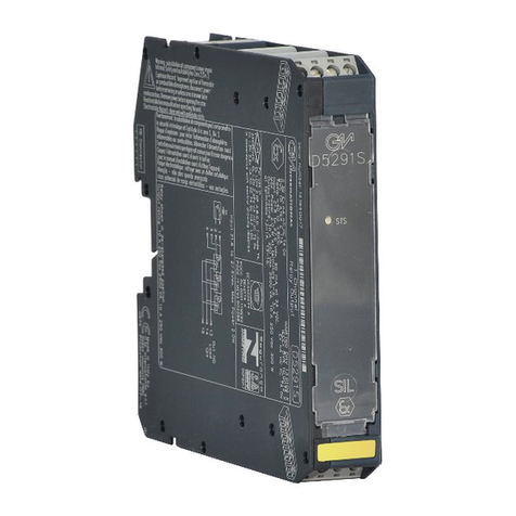
GMI D5291S Instruction Manual

GMI

GMI D5291S Instruction Manual

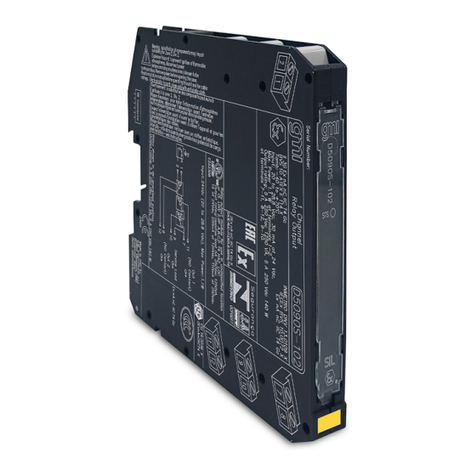
GMI D5095S User guide

GMI

GMI D5095S User guide

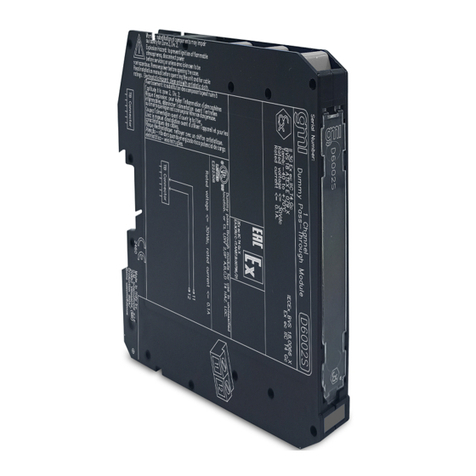
GMI D6002S User manual

GMI

GMI D6002S User manual

GMI D6001S User manual

GMI

GMI D6001S User manual

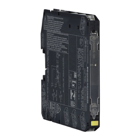
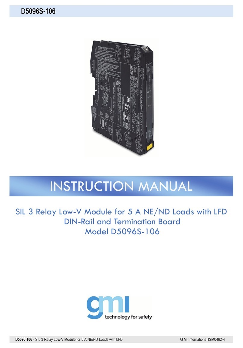
GMI D5096S-106 User manual

GMI

GMI D5096S-106 User manual

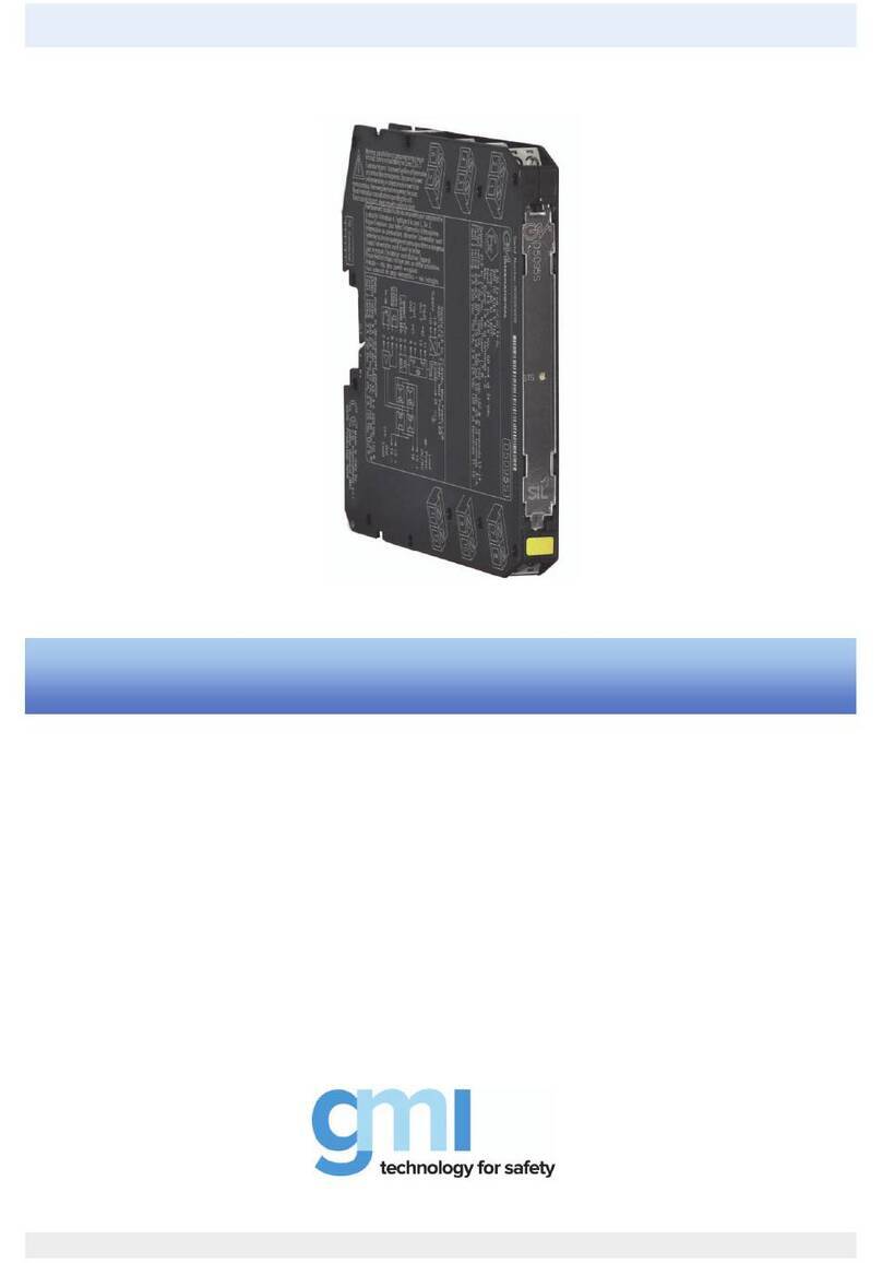
GMI 5039S Series User guide

GMI

GMI 5039S Series User guide

GMI D5290S Instruction Manual

GMI

GMI D5290S Instruction Manual

GMI D5294S Instruction Manual

GMI

GMI D5294S Instruction Manual

GMI D5090S-102 User manual

GMI

GMI D5090S-102 User manual

GMI D5099S User manual

GMI

GMI D5099S User manual

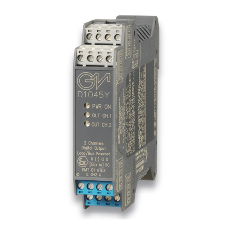
GMI D1045Y User manual

GMI

GMI D1045Y User manual

GMI D5038S Series User guide

GMI

GMI D5038S Series User guide

GMI D5090S Instruction Manual

GMI

GMI D5090S Instruction Manual

GMI D5096S-100 User manual

GMI

GMI D5096S-100 User manual

GMI D1093S Instruction Manual

GMI

GMI D1093S Instruction Manual

GMI D5090S-086 Instruction Manual

GMI

GMI D5090S-086 Instruction Manual

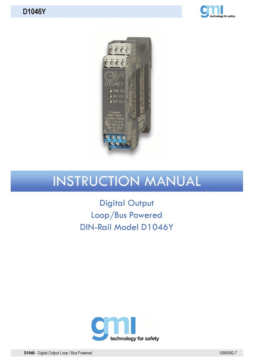
GMI D1046Y User manual

GMI

GMI D1046Y User manual

Popular Control Unit manuals by other brands

Cimberio Cim 790 Technical data sheet

Cimberio

Cimberio Cim 790 Technical data sheet

Powers BILTMORE 800 SERIES installation instructions

Powers

Powers BILTMORE 800 SERIES installation instructions

M-system R7M-EC8B instruction manual

M-system

M-system R7M-EC8B instruction manual

Heliodyne Delta T Pro installation guide

Heliodyne

Heliodyne Delta T Pro installation guide

Emerson Fisher OS2 instruction manual

Emerson

Emerson Fisher OS2 instruction manual

alocity F3D100 manual

alocity

alocity F3D100 manual

Bradley S19-2000EFX Series Installation

Bradley

Bradley S19-2000EFX Series Installation

iWave iW-RainboW-G53M Hardware user's guide

iWave

iWave iW-RainboW-G53M Hardware user's guide

Festo MS6-SV-E operating instructions

Festo

Festo MS6-SV-E operating instructions

Rockwell Automation Trusted TMR Expander Interface manual

Rockwell Automation

Rockwell Automation Trusted TMR Expander Interface manual

M-system R7M-DAC16D instruction manual

M-system

M-system R7M-DAC16D instruction manual

Kikusui PLZ-4W Series user manual

Kikusui

Kikusui PLZ-4W Series user manual

Suttle SAM-VTC user guide

Suttle

Suttle SAM-VTC user guide

OceanAudio 500 SERIES MIXER I/P Handbook

OceanAudio

OceanAudio 500 SERIES MIXER I/P Handbook

Emerson Fisher Vee-Ball V150 instruction manual

Emerson

Emerson Fisher Vee-Ball V150 instruction manual

RHEINTACHO Stroboscope Control Unit operating instructions

RHEINTACHO

RHEINTACHO Stroboscope Control Unit operating instructions

DFI AL9A8 user manual

DFI

DFI AL9A8 user manual

Flomec G2 owner's manual

Flomec

Flomec G2 owner's manual

manuals.online logo
manuals.online logoBrands
  • About & Mission
  • Contact us
  • Privacy Policy
  • Terms and Conditions

Copyright 2025 Manuals.Online. All Rights Reserved.