manuals.online logo
Brands
  1. Home
  2. •
  3. Brands
  4. •
  5. Pfeiffer Vacuum
  6. •
  7. Control Unit
  8. •
  9. Pfeiffer Vacuum EVR 116 User manual

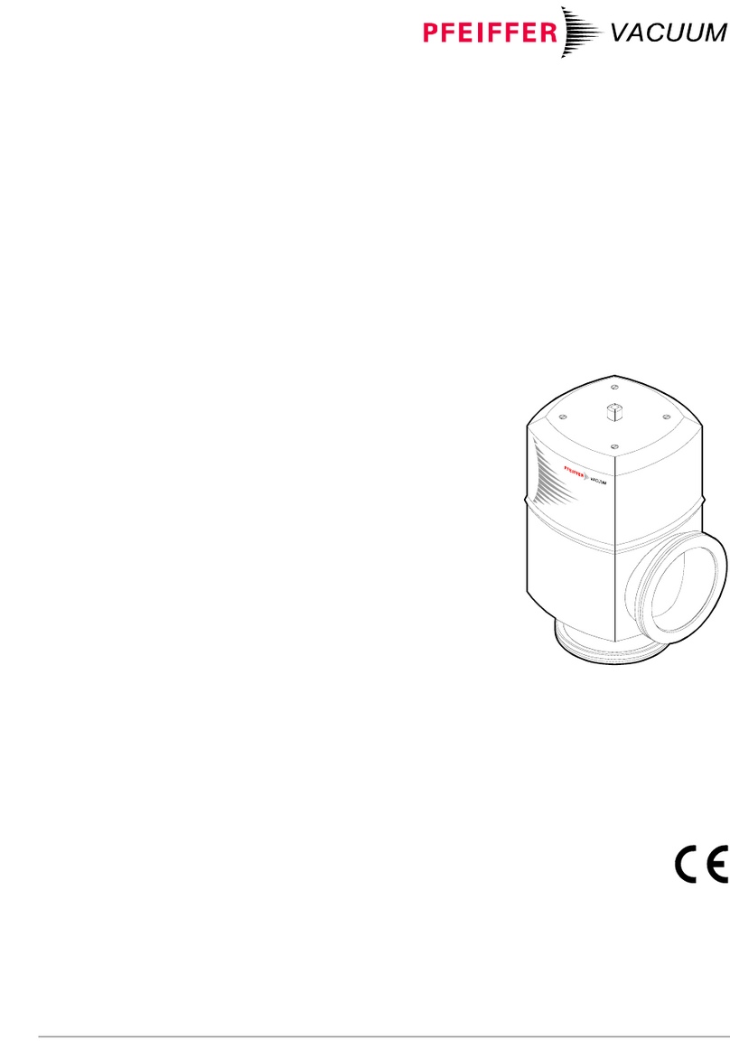
Pfeiffer Vacuum EVR 116 User manual

BP 5056 BEN (2010-11)
A PASSION
FOR PERFECTION
EVR 116
Control Valve
Operating Instructions
Product Identification
In all communications with Pfeiffer Vacuum, please specify
the information on the product nameplate. For convenient
reference copy that information into the nameplate replica
below.
Type:
No:
F-No:
V W
Pfeiffer Vacuum, D-35614 Asslar
Validity
This document applies to products with the part number
PF I39 931.
The part number (No) can be taken from the product
nameplate.
We reserve the right to make technical changes without prior
notice.
All dimensions in mm.
Intended Use
The EVR 116 Control Valve is used together with a control
unit (e.g. Pfeiffer Vacuum RVC 300 control unit) for con-
trolling the pressure in a vacuum system, either with a
variable gas flow (up-stream contol) or with a variable con-
ductance (down-stream control).
It must not be used with liquid gases.
Functional Principle
The Control Valve with integrated motor drive electronics,
which transforms the control signal into a defined valve
position, can be controlled
•with analog voltage,
•via integrated interface or
•via optional RS232 interface.
Safety
Symbols Used
DANGER
Information on preventing any kind of physical injury.
WARNING
Information on preventing extensive equipment and en-
vironmental damage.
Caution
Information on correct handling or use. Disregard can lead
to malfunctions or minor equipment damage.
Personnel Qualifications
Skilled personnel
All work described in this document may only be carried
out by persons who have suitable technical training and
the necessary experience or who have been instructed by
the end-user of the product.
General Safety Instructions
•Adhere to the applicable regulations and take the neces-
sary precautions for the process media used.
Consider possible reactions between the materials and
the process media.
•Adhere to the applicable regulations and take the neces-
sary precautions for all work you are going to do and con-
sider the safety instructions in this document.
•Before beginning to work, find out whether any vacuum
components are contaminated. Adhere to the relevant
regulations and take the necessary precautions when
handling contaminated parts.
Communicate the safety instructions to all other users.
Liability and Warranty
Pfeiffer Vacuum assumes no liability and the warranty be-
comes null and void if end-user or third parties
•disregard the information in this document
•use the product in a non-conforming manner
•make any kind of interventions (modifications, alterations
etc.) on the product
•use the product with accessories and options not listed in
the corresponding product documentation.
The end-user assumes the responsibility in conjunction with
the process media used.
Failures due to contamination or wear and tear, as well as
expendable parts (seals), are not covered by the warranty.
Technical Data
Connection flange
Mounting orientation
Gas flow direction 1)
DN 16 ISO-KF
any
→"Dimensions"
Tightness
Pressure range
Flow rate 2)
With filter on inlet side
With filter on inlet and
Vacuum side
Dead volume
1x10⁻⁹ mbar l/s
1x10⁻⁸ mbar … 2.5 bar (absolute)
5x10⁻⁶ … 1250 mbar l/s
5x10⁻⁶ … 1000 mbar l/s
0.03 cm3
Supply
Operating voltage
Power consumption
Current consump-
tion 3)
24 VDC (±10%)
12 VA
500 mA, 20 … 30 mA rest current
Control
RVC 300
Control voltage
→separate document
0 … +10 VDC
(→"Electrical Connection")
Degree of protection IP 40
Stroke (needle)
Closing / opening time
Integrated sensors
11.5 mm
3 / 4 s
valve open
valve closed
valve needle in movement
Ambient temperature 5 … 40 °C
Materials
Valve housing
Valve needle
Filter
Seals
Dosing sleeve
stainless steel 1.4435
stainless steel 1.4301
stainless steel 1.4404
FPM
fluorplastomer
Weight 0.75 kg
1) The recommended mounting orientation is with the valve seat
in direction to the vacuum chamber
2) For air with Δp = 1 bar
3) Pre-fusing 630 mAT recommended
Dimensions [mm]
DN 16 ISO-KF
Electrical connection Gas flow direction
Protective lid e Valve seat site
Gas flow diagram
The gas flow curve corresponds to a mean value for air with
a pressure difference of 1 bar.
1E-6
1E-5
1E-4
1E-3
1E-2
1E-1
1
10
100
1000
012345678910
UCONTROL [V]
Gas flow [mbar l/s]
Installation
Vacuum Connection
DANGER
DANGER: overpressure in the vacuum system
>1 bar
Injury caused by released parts and harm
caused by escaping process gases can result if
clamps are opened while the vacuum system is
pressurized.
Do not open any clamps while the vacuum
system is pressurized. Use the type of clamps
which are suited to overpressure.
Caution
Caution: vacuum component
Dirt and damages impair the function of the
vacuum component.
When handling vacuum components, take ap-
propriate measures to ensure cleanliness and
prevent damages.
Caution
Caution: dirt sensitive area
Touching the product or parts thereof with bare
hands increases the desorption rate.
Always wear clean, lint-free gloves and use
clean tools when working in this area.
Remove the protective lids and install the product by means
of the small flange fittings.
Accessories:
filter on
vacuum side
Protective lid
O-ring, FPM
ø12.42×1.78
Filter
V-Circlip
J16×1
Seal with centering ring
ISO-KF-connection flange
Clamp
Keep the protective lids.
Electrical Connection
Before connecting or disconnecting the product, turn
off the control system.
nPrepare the connector (the connector is enclosed).
oSolder the connection cable according to the diagram.
SIO interface4)
(Serial Input/Output)
USTG = Control voltage
4) For further information →"Interface"
5) Be careful to correctly connect the poles
Screen
1
2
5
34
Cable socket
Soldering side
0 VDC
1
2
3
4
5
0 ... +10 VDC5)
0 VDC
24 VDC
USTG
USTG
24 VDC+
–
pAssemble the connector.
qPlug in the connector and secure it with the union nut.
Operation
The product is ready for operation as soon as it has been
installed.
If the control valve is operated under dirty operating
conditions, it must be cleaned at regular intervals.
Caution
Caution: power failure
In the event of a power failure the EVR 116
stops and remains in its momentary valve po-
sition.
If the EVR 116 is used together with a Pfeiffer
Vacuum RVC 300 control unit the valve is closed
by the internal capacitor of the EVR 116 in the
event of a power failure.
Gas flow
with filter on the inlet side
(standard) with filter on the inlet and the
vacuum side (accessory)
Flow rate for air:
≤1250 mbar l/s Flow rate for air:
≤1000 mbar l/s
Deinstallation
Electrical Connection
Before connecting or disconnecting the product, turn
off the control system.
Loosen the connector and unplug it.
bp5056ben
(2010-11)
Original: German BP 5056 BDE (2010-11)
Vacuum Connection
DANGER
DANGER: contaminated parts
Contaminated parts can be detrimental to health
and environment.
Before beginning to work, find out whether any
parts are contaminated. Adhere to the relevant
regulations and take the necessary precautions
when handling contaminated parts.
Caution
Caution: vacuum component
Dirt and damages impair the function of the
vacuum component.
When handling vacuum components, take ap-
propriate measures to ensure cleanliness and
prevent damages.
Caution
Caution: dirt sensitive area
Touching the product or parts thereof with bare
hands increases the desorption rate.
Always wear clean, lint-free gloves and use
clean tools when working in this area.
Vent the vacuum system and disassemble the small flange
connection. Place the protective lids.
Seal with centering ring
Clamp
Protective lid ISO-KF-connection flange
Maintenance
DANGER
DANGER: contaminated parts
Contaminated parts can be detrimental to health
and environment.
Before beginning to work, find out whether any
parts are contaminated. Adhere to the relevant
regulations and take the necessary precautions
when handling contaminated parts.
Caution
Caution: vacuum component
Dirt and damages impair the function of the
vacuum component.
When handling vacuum components, take
appropriate measures to ensure cleanliness and
prevent damages.
Caution
Caution: manipulations inside the unit
For technical reasons, manipulations inside the
unit are inadmissible.
Please contact your local Pfeiffer Vacuum ser-
vice center.
Pfeiffer Vacuum assumes no liability and the warranty be-
comes null and void if any service work is carried out, which
is not described in these Operating Instructions.
Cleaning the filter
DANGER
DANGER: cleaning agents
Cleaning agents can be detrimental to health
and environment.
Adhere to the relevant regulations and take the
necessary precautions when handling cleaning
agents and disposing of them. Consider possible
reactions with the product materials.
DANGER
DANGER: cleaning with compressed air
Flying particles can cause eye injuries.
Wear protective glasses.
p
DANGER
DANGER: compressed air
Unprofessionally handling compressed air can
cause physical injuries.
Adhere to the relevant regulations and take the
necessary precautions when handling
compressed air.
Precondition: product deinstalled
nDismantle the filter(s).
O-ring, FPM
ø12.42×1.78
Filter
V-Circlip J16×1
Circlip J17×1
Filter
O-ring, FPM
ø12.42×1.78
oIf necessary, clean the built-in filter(s) by putting it
(them) in alcohol to soak.
pDry the filter(s) with compressed air.
Repair
We recommend returning the product to your local Pfeiffer
Vacuum service center for repair.
Pfeiffer Vacuum assumes no liability and the warranty be-
comes null and void if any repair work is carried out by end-
users or third parties.
Spare Parts and Accessories
Depending on the process, we recommend incorporating an
additional filter on the vacuum side in order to prevent the
valve needle from getting dirty.
When ordering spare parts or accessories, always indicate:
•all information on the product nameplate
•description and ordering number according to the spare
parts or accessories list.
Spare parts
Description Ordering
number
1 Filter, complete
consisting of:
Circlip, staimless steel
1.4404, J17×1
Filter, stainless steel
1.4404
O-ring, FPM, ø12.42×1.78
PT 420 463-T
Accessories
Description Ordering
number
1 Filter complete
consisting of:
O-ring, FPM, ø12.42×1.78
Filter, stainless steel 1.4404
V-Circlip, J16×1
PT 420 463-T
Maximum gas flow depending on filters used
(→"Operation").
Interface
Data transmission
Transmission rate 300 Baud
Data bits 7
Stop bits 2
Voltage level: Logical 0
Logical 1 >7 V
<3 V
Communication
Each transmission from the controller to the valve is initiated
with one ASCII character from "g" to "z" (67hto 7Ah) and
terminated with "CR/LF" (0Dh, 0Ah).
Numeric transmission data are represented as HEX 2 or 3
position hexadecimal values.
For transmission to the valve 0 … 9 and a … f are used, for
transmission to the controller 0 … 9 and A … F.
For two digit numbers a +/– sign can additionally be speci-
fied.
Syntax
The following symbols are used:
$ placeholder for HEX digit (0 … 9, a … f or A … F)
? at the beginning of a response means incorrect entry.
Operating Mode (VMODE)
Analog mode (VMODE = 01)
In analog mode the valve position is defined by the analog
voltage between terminals 3 and 4.
The valve switches to analog mode ≈5 s after the operating
voltage has been applied. The mode can be changed at any
time via the serial interface.
With USTG <0.5 V the valve is closed, with a voltage of 9 V it
is completely open.
Digital mode (VMODE = 02)
In digital mode the valve position is defined via the interface
(with the set commands, →"Command Language").
Command Response Description
h$$ H$$ Writes $$ in VMODE
Possible modes:
h01; Analog mode (set automati-
cally
≈5 s after the operating
voltage has been applied)
h02; Digital mode
Command Language
Set commands
Command Response Description
x X Closes valve and switches
immediately to VMODE = 02
y Y Opens valve and switches
immediately to VMODE = 02
z Z Stops valve movement (only
possible with VMODE = 02)
i I Opens valve with reduced speed
(until "open" or command z)
j J Closes valve with reduced speed
(until "closed" or command z)
g$$$ G$$$ Go to absolute position $$$ x2
Examples:
g100 (close)⇒Response G100
(= Absolute
position 0200h)
gd34 (open)⇒Response GD34
(= Absolute
position 1A68h)
g+$$ G+$$ Increase absolute position by $$
Example:
g+10 ⇒Response G+10
(= open by 16 increments)
g-$$ G-$$ Decrease absolute position by $$
Example:
g-01 ⇒Response G-01
(= close by 1 increment)
Inquiry commands
Command Response Description
h? H$$ Output the VMODE
p? $$$$ Actual position
(Normal range 0200H to 1A68H)
s? S$$$ Status information (12 Bit)
t? T$$$ Temperature in valve (12 Bit)
v? V$$$ Version number (=V120)
Data format of the status information
The result of the status inquiry is a 3-position HEX number
that represents the following data sequence:
{D3, D2, D1, D0}
D3 Logical state of the light barrier "close" (OK3)
D2 Logical state of the light barrier "open" (OK2)
D1 Logical state of the light barrier "rotation" (OK1)
D0 Parameter are at the default values
{D7, D6, D5, D4}
D7 Temperature error (max. temperature exceedet),
triggers "close" and power off ("t?" < T$53h)
D6 Temperature warning ("t?" < T$60h)
D5 Operating voltage too low
D4 Operating voltage warning
{D11, D10, D9, D8}
D11 Reserve
D10 Blocking of movement has occurred
D9 Initialization completed
D8 Status message from INT-timer
S$$$
Temperature
The result of the temperature inquiry is a 3-position HEX
number of which only the last two digits are relevant. The
lower this number the higher the temperature is at the
measuring point.
The EVR 116 is switched off when this value is < 53h.
{D7, D6, D5, D4} {D3, D2, D1, D0}
Valve temperature
The lower this number the higher the temperature.
A value < T$53h, triggers an error.
A value < T$60h, triggers a warning.
Not relevant
T$$$
Returning the Product
WARNING
WARNING: forwarding contaminated products
Contaminated products (e.g. radioactive, toxic,
caustic or biological hazard) can be detrimental
to health and environment.
Products returned to Pfeiffer Vacuum should
preferably be free of harmful substances. Ad-
here to the forwarding regulations of all involved
countries and forwarding companies and en-
close a duly completed declaration of contami-
nation *).
*) Form under www.pfeiffer-vacuum.net
Products that are not clearly declared as "free of harmful
substances" are decontaminated at the expense of the
customer.
Products not accompanied by a duly completed declaration
of contamination are returned to the sender at his own
expense.
Disposal
DANGER
DANGER: contaminated parts
Contaminated parts can be detrimental to health
and environment.
Before beginning to work, find out whether any
parts are contaminated. Adhere to the relevant
regulations and take the necessary precautions
when handling contaminated parts.
Separating the components
After disassembling the product, separate its components
according to the following criteria:
•Contaminated components
Contaminated components (radioactive, toxic, caustic, or
biological hazard etc.) must be decontaminated in accor-
dance with the relevant national regulations, separated
according to their materials, and disposed of.
•Other components
Such components must be separated according to their
materials and recycled.
Berliner Straße 43
D–35614 Asslar
Deutschland
Tel +49 (0) 6441 802-0
Fax +49 (0) 6441 802-202
[email protected]
www.pfeiffer-vacuum.net
This manual suits for next models

1

Other Pfeiffer Vacuum Control Unit manuals

Pfeiffer Vacuum DCU 002 User manual

Pfeiffer Vacuum

Pfeiffer Vacuum DCU 002 User manual

Pfeiffer Vacuum PM Z01 310 User manual

Pfeiffer Vacuum

Pfeiffer Vacuum PM Z01 310 User manual

Pfeiffer Vacuum UDV 040 User manual

Pfeiffer Vacuum

Pfeiffer Vacuum UDV 040 User manual

Pfeiffer Vacuum TPG 366 MAXIGAUGE User manual

Pfeiffer Vacuum

Pfeiffer Vacuum TPG 366 MAXIGAUGE User manual

Pfeiffer Vacuum EVC 116 M User manual

Pfeiffer Vacuum

Pfeiffer Vacuum EVC 116 M User manual

Pfeiffer Vacuum DCU 002 User manual

Pfeiffer Vacuum

Pfeiffer Vacuum DCU 002 User manual

Pfeiffer Vacuum DualGauge TPG 262 User manual

Pfeiffer Vacuum

Pfeiffer Vacuum DualGauge TPG 262 User manual

Pfeiffer Vacuum TPG 256 A User manual

Pfeiffer Vacuum

Pfeiffer Vacuum TPG 256 A User manual

Pfeiffer Vacuum EVN 116 User manual

Pfeiffer Vacuum

Pfeiffer Vacuum EVN 116 User manual

Pfeiffer Vacuum N Series User manual

Pfeiffer Vacuum

Pfeiffer Vacuum N Series User manual

Pfeiffer Vacuum EVI 005 MI User manual

Pfeiffer Vacuum

Pfeiffer Vacuum EVI 005 MI User manual

Pfeiffer Vacuum TPG 500 User manual

Pfeiffer Vacuum

Pfeiffer Vacuum TPG 500 User manual

Pfeiffer Vacuum CENTERONE-TWO User manual

Pfeiffer Vacuum

Pfeiffer Vacuum CENTERONE-TWO User manual

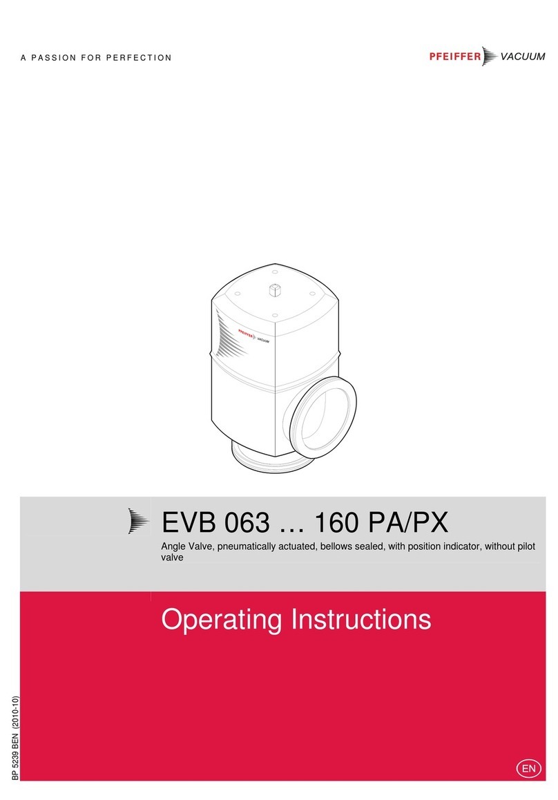
Pfeiffer Vacuum EVB 16 P A User manual

Pfeiffer Vacuum

Pfeiffer Vacuum EVB 16 P A User manual

Pfeiffer Vacuum DVB 016 PX User manual

Pfeiffer Vacuum

Pfeiffer Vacuum DVB 016 PX User manual

Pfeiffer Vacuum HPU 001 User manual

Pfeiffer Vacuum

Pfeiffer Vacuum HPU 001 User manual

Pfeiffer Vacuum TPG 361 User manual

Pfeiffer Vacuum

Pfeiffer Vacuum TPG 361 User manual

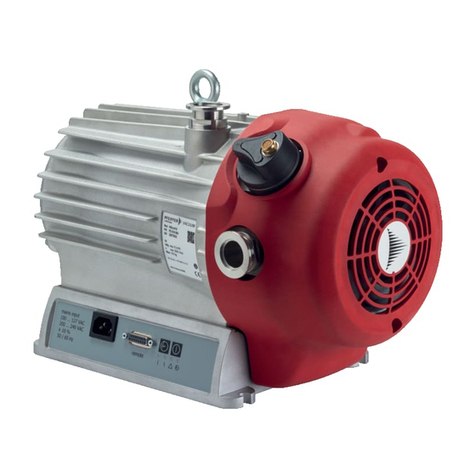
Pfeiffer Vacuum HISCROLL User manual

Pfeiffer Vacuum

Pfeiffer Vacuum HISCROLL User manual

Pfeiffer Vacuum EVB 160 PA User manual

Pfeiffer Vacuum

Pfeiffer Vacuum EVB 160 PA User manual

Pfeiffer Vacuum PM Z01 290 User manual

Pfeiffer Vacuum

Pfeiffer Vacuum PM Z01 290 User manual

Pfeiffer Vacuum TPG 300 User manual

Pfeiffer Vacuum

Pfeiffer Vacuum TPG 300 User manual

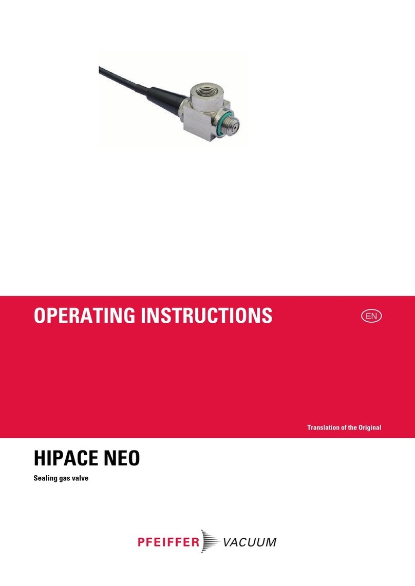
Pfeiffer Vacuum HIPACE NEO User manual

Pfeiffer Vacuum

Pfeiffer Vacuum HIPACE NEO User manual

Pfeiffer Vacuum EVL 063 P User manual

Pfeiffer Vacuum

Pfeiffer Vacuum EVL 063 P User manual

Pfeiffer Vacuum UDV 146 User manual

Pfeiffer Vacuum

Pfeiffer Vacuum UDV 146 User manual

Popular Control Unit manuals by other brands

ADIC Scalar 100 FCR-1 Installation and operating guide

ADIC

ADIC Scalar 100 FCR-1 Installation and operating guide

bolid S2000-BI Rev.02 instruction manual

bolid

bolid S2000-BI Rev.02 instruction manual

DMQ A12V-U112 Hardware installation manual

DMQ

DMQ A12V-U112 Hardware installation manual

Weidmüller WCU 501 manual

Weidmüller

Weidmüller WCU 501 manual

EXFO IQ-3100 instruction manual

EXFO

EXFO IQ-3100 instruction manual

roco multiMAUSPRO Getting started

roco

roco multiMAUSPRO Getting started

JDV JBSM Installation, operation and maintenance

JDV

JDV JBSM Installation, operation and maintenance

Motrona ZU 252 operating instructions

Motrona

Motrona ZU 252 operating instructions

IBC P-270 installation instructions

IBC

IBC P-270 installation instructions

Greentek VECTRA SERIES Installation and owner's guide

Greentek

Greentek VECTRA SERIES Installation and owner's guide

SKF Lincoln 85307 installation instructions

SKF

SKF Lincoln 85307 installation instructions

Watts Industries PR500 instruction manual

Watts Industries

Watts Industries PR500 instruction manual

Midian TVS-2-TAIT manual

Midian

Midian TVS-2-TAIT manual

BENDIX R7 VALVE 3-04 SPANISH Informacion de servicio

BENDIX

BENDIX R7 VALVE 3-04 SPANISH Informacion de servicio

Azbil Actival VY51 J Series Specifications and installation

Azbil

Azbil Actival VY51 J Series Specifications and installation

Johnson Controls METASYS TC-9102 Series Technical bulletin

Johnson Controls

Johnson Controls METASYS TC-9102 Series Technical bulletin

Leica LID Module 1.0 Instructions for use

Leica

Leica LID Module 1.0 Instructions for use

Lawler 310 Installation & maintenance manual

Lawler

Lawler 310 Installation & maintenance manual

manuals.online logo
manuals.online logoBrands
  • About & Mission
  • Contact us
  • Privacy Policy
  • Terms and Conditions

Copyright 2025 Manuals.Online. All Rights Reserved.