ILX Lightwave LDC-3916338 User manual

-~
ARTISAN
®
~I
TECHNOLOGY
GROUP
Your definitive source
for
quality
pre-owned
equipment.
Artisan Technology
Group
Full-service,
independent
repair
center
with
experienced
engineers
and
technicians
on staff.
We
buy
your
excess,
underutilized,
and
idle
equipment
along
with
credit
for
buybacks
and
trade-ins
.
Custom
engineering
so
your
equipment
works
exactly as
you
specify.
•
Critical
and
expedited
services
•
Leasing
/
Rentals/
Demos
• In
stock/
Ready-to-ship
•
!TAR-certified
secure
asset
solutions
Expert
team
ITrust
guarantee
I
100%
satisfaction
All
tr
ademarks,
br
a
nd
names, a
nd
br
a
nd
s a
pp
earing here
in
are
th
e property of
th
e
ir
r
es
pecti
ve
ow
ner
s.
Find the Newport / ILX Lightwave LDC-3916376 at our website: Click HERE

User’s Guide
3.0 Amp Laser Diode
Current Source Module
LDC-3916338
ILX Lightwave Corporation P. O.Box 6310 Bozeman, MT, U.S.A. 59771 :· · · 1-800-459-9459 · ·
www.ilxlightwave.com
U.S. & Canada International Inquiries: 406-586-1244 Fax 406-586-9405
E-mail: [email protected]
70031502_7/01
Artisan Technology Group - Quality Instrumentation ... Guaranteed | (888) 88-SOURCE | www.artisantg.com

Artisan Technology Group - Quality Instrumentation ... Guaranteed | (888) 88-SOURCE | www.artisantg.com

Safety and Warranty Information
! ! ! ! ! ! ! ! ! ! ! ! ! ! ! ! ! !
S
AFETY
AND
W
ARRANTY
I
NFORMATION
The Safety and Warranty Information section provides details about cautionary symbols used in the
manual, safety markings used on the instrument, and information about the Warranty including
Customer Service contact information.
Safety Information and the Manual
Throughout this manual, you will see the words Caution and Warning indicating potentially
dangerous or hazardous situations which, if not avoided, could result in death, serious or minor
injury, or damage to the product. Specifically:
!
CAUTION
Caution indicates a potentially hazardous situation which can result in minor or
moderate injury or damage to the product or equipment.
WARNING
Warning indicates a potentially dangerous situation which can result in serious injury or
death.
WARNING
Visible and/or invisible laser radiation. Avoid direct exposure to the beam.
General Safety Considerations
If any of the following conditions exist, or are even suspected, do not use the instrument until safe
operation can be verified by trained service personnel:
•Visible damage
•Severe transport stress
•Prolonged storage under adverse conditions
•Failure to perform intended measurements or functions
If necessary, return the instrument to ILX Lightwave, or authorized local ILX Lightwave distributor,
for service or repair to ensure that safety features are maintained (see the contact information on
page vi).
All instruments returned to ILX Lightwave are required to have a Return Authorization Number
assigned by an official representative of ILX Lightwave Corporation. See Returning an Instrument on
page v for more information.
Artisan Technology Group - Quality Instrumentation ... Guaranteed | (888) 88-SOURCE | www.artisantg.com

Safety and Warranty Information
S
AFETY
S
YMBOLS
This section describes the safety symbols and classifications.
Technical specifications including electrical ratings and weight are included within the manual. See
the Table of Contents to locate the specifications and other product information. The following
classifications are standard across all ILX Lightwave products:
•Indoor use only
•Ordinary Protection: This product is NOT protected against the harmful ingress of moisture.
•Class I Equipment (grounded type)
•Mains supply voltage fluctuations are not to exceed ±10% of the nominal supply voltage.
•Pollution Degree II
•Installation (overvoltage) Category II for transient overvoltages
•Maximum Relative Humidity: <80% RH, non−condensing
•Operating temperature range of 0 °C to 40 °C
•Storage and transportation temperature of ˘40 °C to 70 °C
•Maximum altitude: 3000 m (9843 ft)
•This equipment is suitable for continuous operation.
Safety Marking Symbols
This section provides a description of the safety marking symbols that appear on the instrument.
These symbols provide information about potentially dangerous situations which can result in death,
injury, or damage to the instrument and other components.
Caution,
refer to
manual
Earth
ground
Terminal
Alternating
current
Visible and/or
invisible laser
radiation
Caution, risk
of electric
shock
Protective
Conductor
Terminal
Caution, hot
surface
Frame or
chassis
Terminal
On: In position of a bistable push control. The
slash (I) only denotes that mains are on.
Off: Out position of a bistable push control.
The circle (O) only denotes that mains are off.
or
(I) or
(O)
Artisan Technology Group - Quality Instrumentation ... Guaranteed | (888) 88-SOURCE | www.artisantg.com

Safety and Warranty Information
W
ARRANTY
ILX LIGHTWAVE CORPORATION warrants this instrument to be free from defects in material and
workmanship for a period of one year from date of shipment. During the warranty period, ILX will
repair or replace the unit, at our option, without charge.
Limitations
This warranty does not apply to fuses, lamps, defects caused by abuse, modifications, or to use of
the product for which it was not intended.
This warranty is in lieu of all other warranties, expressed or implied, including any implied warranty
of merchantability or fitness for any particular purpose. ILX Lightwave Corporation shall not be liable
for any incidental, special, or consequential damages.
If a problem occurs, please contact ILX Lightwave Corporation with the instrument’s serial number,
and thoroughly describe the nature of the problem.
Returning an Instrument
If an instrument is to be shipped to ILX Lightwave for repair or service, be sure to:
1Obtain a Return Authorization number (RA) from ILX Customer Service.
2Attach a tag to the instrument identifying the owner and indicating the required service or
repair. Include the instrument serial number from the rear panel of the instrument.
3Attach the anti−static protective caps that were shipped with the instrument and place the
instrument in a protective anti−static bag.
4Place the instrument in the original packing container with at least 3 inches (7. 5 cm) of
compressible packaging material. Shipping damage is not covered by this warranty.
5Secure the packing box with fiber reinforced strapping tape or metal bands.
6Send the instrument, transportation pre−paid, to ILX Lightwave. Clearly write the return
authorization number on the outside of the box and on the shipping paperwork. ILX
Lightwave recommends you insure the shipment.
If the original shipping container is not available, place your instrument in a container with at least 3
inches (7.5 cm) of compressible packaging material on all sides.
Repairs are made and the instrument returned transportation pre−paid. Repairs are warranted for the
remainder of the original warranty or for 90 days, whichever is greater.
Claims for Shipping Damage
When you receive the instrument, inspect it immediately for any damage or shortages on the
packing list. If the instrument is damaged, file a claim with the carrier. The factory will supply you
with a quotation for estimated costs of repair. You must negotiate and settle with the carrier for the
amount of damage.
Artisan Technology Group - Quality Instrumentation ... Guaranteed | (888) 88-SOURCE | www.artisantg.com

Safety and Warranty Information
Comments, Suggestions, and Problems
To ensure that you get the most out of your ILX Lightwave product, we ask that you direct any
product operation or service related questions or comments to ILX Lightwave Customer Support.
You may contact us in whatever way is most convenient:
Phone . . . . . . . . . . . . . . . . . . . . . . . . . . . (800) 459−9459 or (406) 586−1244
Fax . . . . . . . . . . . . . . . . . . . . . . . . . . . . . . . . . . . . . . . . . . . . . (406) 586−9405
Email. . . . . . . . . . . . . . . . . . . . . . . . . . . . . . . . . . . .support@ilxlightwave.com
Or mail to:
ILX Lightwave Corporation
P. O. Box 6310
Bozeman, Montana, U.S.A 59771
www.ilxlightwave.com
When you contact us, please have the following information:
If ILX Lightwave determines that a return to the factory is necessary, you are issued a Return
Authorization (RA) number. Please mark this number on the outside of the shipping box.
You or your shipping service are responsible for any shipping damage when returning the
instrument to ILX Lightwave; ILX recommends you insure the shipment. If the original shipping
container is not available, place your instrument in a container with at least 3 inches (7.5cm) of
compressible packaging material on all sides.
We look forward to serving you even better in the future!
Model Number:
Serial Number:
End−user Name:
Company:
Phone:
Fax:
Description or sketch of what
is connected to the ILX
Lightwave instrument:
Description of the problem:
Artisan Technology Group - Quality Instrumentation ... Guaranteed | (888) 88-SOURCE | www.artisantg.com

Table of Contents
Module Instruction Manual
Chapter 1 Introduction to the LDC-3916338 3.0 Amp Laser Diode Current Source
Module
Introduction ...............................................................................................................................................................1
Safety Symbols and Terms..............................................................................................................................................1
Product Overview............................................................................................................................................................2
Installing your LDC-3916338 Laser Diode Current Source Module...............................................................................2
How to Contact Customer Service..................................................................................................................................3
LDC-3916338 3.0 Amp Current Source Module Specifications.....................................................................................5
Chapter 2 How to Operate Your LDC-3916338 Laser Diode Current Source Module
Introduction ...............................................................................................................................................................1
Connecting to the Laser Controller..................................................................................................................................2
Operating the Laser Current Source from the Front Panel..............................................................................................5
Operating a Laser in Constant Current Mode.................................................................................................................5
Operating a Laser in Constant Power Mode...................................................................................................................8
Conditions which will Automatically Shut Off the Laser Output ................................................................................12
Chapter 3 Operating in Remote Control
Introduction ...............................................................................................................................................................1
Remote Configuration......................................................................................................................................................1
LDC-3916338 Laser Diode Current Source Command Set .............................................................................................1
Status Reporting..............................................................................................................................................................4
Chapter 4 Command Reference
Introduction ...............................................................................................................................................................1
LDC-3916338 Device-Dependent Commands................................................................................................................3
LDC-3916338 Device-Command Reference....................................................................................................................3
Chapter 5 Calibration and Troubleshooting Guide
Introduction ...............................................................................................................................................................1
Calibration Overview.......................................................................................................................................................1
Local Calibration of the Laser Current Source.................................................................................................................3
Remote Calibration of the 3916338 Current Source Module..........................................................................................6
Troubleshooting Guide..................................................................................................................................................10
Artisan Technology Group - Quality Instrumentation ... Guaranteed | (888) 88-SOURCE | www.artisantg.com

Artisan Technology Group - Quality Instrumentation ... Guaranteed | (888) 88-SOURCE | www.artisantg.com

INTRODUCTION TO THE LDC-3916338 3.0 AMP CURRENT SOURCE MODULE CHPT 1
CHAPTER 1 1
INTRODUCTION TO THE LDC-3916338 3.0 AMP LASER DIODE CURRENT SOURCE MODULE 1
INTRODUCTION 1
SAFETY SYMBOLS AND TERMS 1
PRODUCT OVERVIEW 2
INSTALLING YOUR LDC-3916338 LASER DIODE CURRENT SOURCE MODULE 2
Installation into LDC-3916 or LDC-3908 Laser Diode Controller Mainframe 2
HOW TO CONTACT CUSTOMER SERVICE 3
Calibration and Repair Services 3
General Shipping Instructions 3
LDC-3916338 3.0 AMP CURRENT SOURCE MODULE SPECIFICATIONSERROR! BOOKMARK NOT
DEFINED.
Laser Current Source Specifications 4
Artisan Technology Group - Quality Instrumentation ... Guaranteed | (888) 88-SOURCE | www.artisantg.com

Artisan Technology Group - Quality Instrumentation ... Guaranteed | (888) 88-SOURCE | www.artisantg.com

INTRODUCTION TO THE LDC-3916338 3.0 AMP CURRENT SOURCE MODULE CHPT 1
PAGE 1
CHAPTER 1
INTRODUCTION TO THE LDC-3916338 3.0 AMP LASER DIODE CURRENT
SOURCE MODULE
INTRODUCTION
This chapter is an introduction to the LDC-3916338 3.0 Amp Laser Diode Current Source Module for the LDC-3916 or
LDC-3908 LD Controller Mainframes. Contained in Chapter 1 is unpacking information, instructions on how to install
and apply power, and safety considerations and instructions. It also contains some maintenance information, and
specifications.
WARNING
If any of the following symptoms exist, or are even suspected, remove the LDC-3916338
Module from service. Do not use LDC-3916xxx modules until safe operation can be verified
by trained service personnel.
1. Visible damage
2. Severe transport stress
3. Prolonged storage under adverse conditions
4. Failure to perform intended measurements or functions
If necessary, return the LDC-3916338 modules to ILX Lightwave for service and repair to ensure
that safety features are maintained.
SAFETY SYMBOLS AND TERMS
The following safety terms are used in this manual:
•The WARNING heading explains dangers that could result in personal injury or death.
•The CAUTION heading explains hazards that could damage your instrument.
•The NOTES heading gives information to the user that may be beneficial in the use of the instrument and to the
devices being tested.
Artisan Technology Group - Quality Instrumentation ... Guaranteed | (888) 88-SOURCE | www.artisantg.com

INTRODUCTION TO THE LDC-3916338 3.0 AMP CURRENT SOURCE MODULE CHPT 1
PAGE 2
The following symbols are used in this manual and on the instrument:
Earth Ground and/or Protective Conductor Terminal
Caution: Refer to accompanying documents
Caution: Risk of Electrical Shock
Instrument Power Off
Instrument Power On
PRODUCT OVERVIEW
The LDC-3916338 Laser Diode Current Source Module contains one fully independent current source. The current
sources provide high stability output up to a maximum drive current of 3.0 Amps, with fully redundant current limits
and multiple laser protection features such as contact bounce detection, compliance voltage limit adjust, and 4-wire
voltage measurement for precise laser diode forward voltage measurement.
INSTALLING YOUR LDC-3916338 LASER DIODE CURRENT SOURCE MODULE
Installation into LDC-3916 or LDC-3908 Laser Diode Controller Mainframe
If you are receiving this new module for installation into a previously purchased LDC-3916 or LDC-3908 mainframe,
follow the instructions below. If your system was configured at the factory with your desired modules skip this
section.
CAUTION
Static discharge can damage your new Laser Diode Current Source Module. Be certain you use
proper grounding procedures before you unpack and install your controller module(s) into the
LDC-3916 or LDC-3908 Mainframe.
Inspect the module for any visible shipping damage that may have occurred before inserting the
module into the mainframe. Pay special attention to the copper shielding material on the back
edge of the module.
Be sure that the LDC-3916 or LDC-3908 Mainframe power is off before inserting your new laser
diode controller module.
Unwrap the module from the anti-static bag it was packaged in.
Insert the module into the desired slot from the rear of the LDC-3916 or LDC-3908 Mainframe. Each module is
supported by two plastic card guides inside of the mainframe. Insert the module, 40-pin connector first, by lining up
the edges of the module frame with the appropriate card guides (one on the top and one on the bottom). Carefully
slide the module into the mainframe slot until the connector is seated. You will have to push a little harder to seat the
module. The rear panel of the module should be flush with the mainframe when properly inserted. Fasten the
module to the mainframe with the two screws located at the top and bottom of the module rear panel.
Artisan Technology Group - Quality Instrumentation ... Guaranteed | (888) 88-SOURCE | www.artisantg.com

INTRODUCTION TO THE LDC-3916338 3.0 AMP CURRENT SOURCE MODULE CHPT 1
PAGE 3
HOW TO CONTACT CUSTOMER SERVICE
If you have any questions or comments related to product operation or service, please contact Customer Support at
1-800-459-9459 (USA and Canada) or 406-586-1244 (International); by fax at 406-586-9405; or E-mail us at
Please have the following information available (if applicable):
NOTE: All ILX Lightwave modules are identified byan seven-digit serial number located on the rear
panel. The first three digits are the model number; the last four identify your module specifically.
1) Product Model: ________________________________________________
2) Unit Serial Number: ________________________________________________
3) End user name and telephone/fax
Name: ________________________________________________
Company: ________________________________________________
Phone: ________________________________________________
Fax: ________________________________________________
4) Description/sketch of what is connected to the ILX Lightwave instrument.
5) Description of the problem.
Calibration and Repair Services
You may have to return your current source module to an ILX Lightwave facility at some time for repair, calibration or
service whether it is under warranty or not. There is a charge for repairs after the warranty period has expired.
Contact an ILX Lightwave service representative for shipping instructions prior to returning the instrument. Have
the above information available when you call. A return authorization number will be given to you at the time of your
request for repair or service. Please use this number in all communications concerning your instrument.
General Shipping Instructions
If you need to ship your LDC-3916338 Laser Diode Current Source Module back to the factory for repair, be sure that
the module is packaged in an anti-static bag and an enclosure with cushioning material to prevent damage to the
module during shipment (use the original shipping containers and accessories if possible). Re-install the ESD
protective caps on the rear panel over the 9-pin connector. Shipping damage is not covered under warranty.
Attach to the module a copy of the completed service form above. We suggest that you insure the shipment.
Ship the module to:
UNITED STATES
ILX LIGHTWAVE CORP.
31950 E. Frontage Rd.
Bozeman, Montana 59715
PH: 406-586-1244
FAX: 406-586-9405
OUTSIDE THE UNITED STATES
Contact the local distributor.
Artisan Technology Group - Quality Instrumentation ... Guaranteed | (888) 88-SOURCE | www.artisantg.com

INTRODUCTION TO THE LDC-3916338 3.0 AMP CURRENT SOURCE MODULE CHPT 1
PAGE 4
Laser Current Source Specifications1
MODEL NUMBER 3916338 Single 3.0A
DRIVE CURRENT OUTPUT
Output Current Range: 0 to 3000mA
Setpoint Resolution: 80 µA
Setpoint Accuracy:2±0.1% of full scale
Compliance Voltage: 4.5 V (adjustable voltage limit)
Temperature Coefficient: ≤100ppm/°C
Short Term Stability (1 hr.):3≤50 ppm
Long Term Stability (24 hr.):4≤75 ppm
Noise and Ripple:5
High Bandwidth Mode: < 36µA rms
Low Bandwidth Mode: < 24µA rms
Transients:
Operational: 6< 5mA
1kV EFT / Surge:7< 5 mA / < 10mA
LASER DRIVE LIMIT SETTINGS
Current Limit Range: 0 to 3000mA
Current Limit Resolution: 1.025 mA
Current Limit Accuracy: ±9 mA
Voltage Limit Range: 0 to 7.5V
Voltage Limit Resolution: 0.2V
PHOTODIODE FEEDBACK
Type: Differential 10ΩInput,
Selectable Zero Bias or 5V Reverse Bias
PD Current Range: 0 to 5000µA
Output Stability:8±0.01%
Accuracy, Setpoint (% of FS): ± 0.1%
EXTERNAL ANALOG MODULATION
Input :90 to 8.0 V, 50Ω
Transfer Function: 375 mA / V ±10 %
High Bandwidth Mode, Small Signal Bandwidth:10 DC to 0.6 MHz
High Bandwidth Mode, Large Signal Bandwidth:11 DC to 0.6 MHz
Low Bandwidth Mode: DC to 30 kHz
DRIVE CURRENT MEASUREMENT
(DISPLAY)
Output Current Range: 0 to 3000.0mA
Output Current Resolution: 0.01 mA
Output Current Accuracy (@25°C): ± 0.07% of Full Scale
Photodiode Current Range: 0 to 5000µA
PD Current Resolution: 0.1 µA
PD Current Accuracy (@25°C): ± 2µA
PD Responsivity Range:12 0.00 to 1000.00µA/ mW
PD Responsivity Resolution: 0.01 µA/ mW
Optical Power Range: 0.00 to 5000.0mW
Optical Power Resolution: 100 µW
Forward Voltage Range: 0.00 to 7.5 V
Forward Voltage Resolution: 10 mV (1 mV GPIB)
Forward Voltage Accuracy:13 ±7 mV (± 2 mV GPIB)
CURRENT SOURCE NOTES:
1. All values relate to a one-hour warm-up period.
2. Accuracy is 0.15% above 2.5 Amps after 1hr warm-up period.
3. Over any 1-hour period, half-scale output.
4. Over any 24-hour period, half-scale output.
5. Measured optically, evaluating noise intensity of a laser diode into a photodetector with 150kHz Bandwidth.
6. Maximum output current transient resulting from normal operational situations (e.g., power on-off, current on-off), as well as accidental situations (e.g., power
line plug removal).
7. Maximum output current transient resulting from a 1000V power-line transient spike.
8. Maximum monitor photodiode current drift over any 30 minute period. Assumes zero drift inresponsivity of photodiode.
9. Modulation input is 50Ωterminated inside the mainframe.
10. 250 mA Setpoint, 50mA modulation current, 1Ωload. High bandwidth mode.
11. 50% modulation at mid-scale output, 1Ωload. High bandwidth mode.
12. Responsivity value is user-defined and is used to calculate the optical power.
13. Four-wire voltage measurement while driving calibration load. Specification valid for values above 10 mV.
Artisan Technology Group - Quality Instrumentation ... Guaranteed | (888) 88-SOURCE | www.artisantg.com

HOW TO OPERATE YOUR LDC-3916338 3.0 AMP CURRENT SOURCE MODULE CHPT 2
CHAPTER 2 1
HOW TO OPERATE YOUR LDC-3916338 LASER DIODE CURRENT SOURCE MODULE 1
INTRODUCTION 1
CONNECTING TO THE LASER CURRENT SOURCE 2
Interlock Connections 4
Four-Wire Voltage Sense 4
Photodiode Connections 4
Grounding considerations 4
OPERATING THE LASER CURRENT SOURCE FROM THE FRONT PANEL 5
OPERATING A LASER IN CONSTANT CURRENT MODE 5
Entering the Laser Channel Setup Menu 5
Selecting the Mode of Control 6
Setting the Current Limit 6
Setting the Constant Current Value 6
Setting the Voltage Limit 6
Enabling the Modulation Input 7
Setting Photodiode Bias Voltage 7
Turning the Laser Current Source On 7
OPERATING A LASER IN CONSTANT POWER (P) MODE 8
Calculating Photodiode Responsivity Values 8
Entering the Laser Channel Setup Menu 8
Selecting the Mode of Control 8
Setting the Current Limit 9
Setting the Voltage Limit 9
Setting the Power Limit 10
Adjusting the Constant Power Setting 10
Setting the Responsivity Value (CalPD) 10
Setting the Photodiode Bias Voltage 11
Enabling the Modulation Input 11
Constant Power Mode If CalPD is Unknown 11
Turning the Laser Current Source On 11
CONDITIONS WHICH WILL AUTOMATICALLY SHUT OFF THE LASER OUTPUT 12
Laser Error Indicators 13
Artisan Technology Group - Quality Instrumentation ... Guaranteed | (888) 88-SOURCE | www.artisantg.com

Artisan Technology Group - Quality Instrumentation ... Guaranteed | (888) 88-SOURCE | www.artisantg.com

HOW TO OPERATE YOUR LDC-3916338 3.0 AMP CURRENT SOURCE MODULE CHPT 2
PAGE 1
CHAPTER 2
HOW TO OPERATE YOUR LDC-3916338 LASER DIODE CURRENT SOURCE
MODULE
INTRODUCTION
This chapter introduces you to the operation of the LDC-3916338 LD Current Source's control functions. It offers
instructions for connecting your lasers to the current sources. This chapter also contains step by step procedures
that teach you how to operate your module in Constant Current Mode or Constant Power Mode. We recommend
that you review the contents of this chapter at a minimum before operating your new LDC-3916338 Laser Diode
Current Source.
LDC-3916338 SERIES CURRENT SOURCE DEFAULT CONFIGURATION
LASER CONTROLLER
LASER output off
LAS current set point (LDI or Iset) = 50 mA
LAS current limit (LIM:I or Ilim) = 150 mA
LAS voltage limit (LIM:V or Vlim) = 5.0 V
LAS Mode = Constant Current, low bandwidth mode (MODE:ILBW or Ilbw)
Modulation off
Optical power set point (MDP or Pset) = 3.0 mW
Monitor responsivity (CALPD or CalPD) = 0.0µA/mW
Optical power limit (LIM:MDP or Plim) = 500 mW
Monitor PD Bias off
LASER STEP value = 0.1mA
Monitor PD current set point (MDI or Ipdset) = 100µA
Table 2.1 LDC-3916338 Series Current Source Default Settings
Artisan Technology Group - Quality Instrumentation ... Guaranteed | (888) 88-SOURCE | www.artisantg.com
HOW TO OPERATE YOUR LDC-3916338 3.0 AMP CURRENT SOURCE MODULE CHPT 2
PAGE 2
CONNECTING TO THE LASER CURRENT SOURCE
When connecting your laser diode or any other sensitive devices to the LDC-3916338 Laser Diode Current Source
Modules, we recommend that the instrument be powered up and the LASER output be off. In this condition, a low
impedance shunt is active across the output terminals. When disconnecting devices, it is only necessary to turn the
LASER Output off.
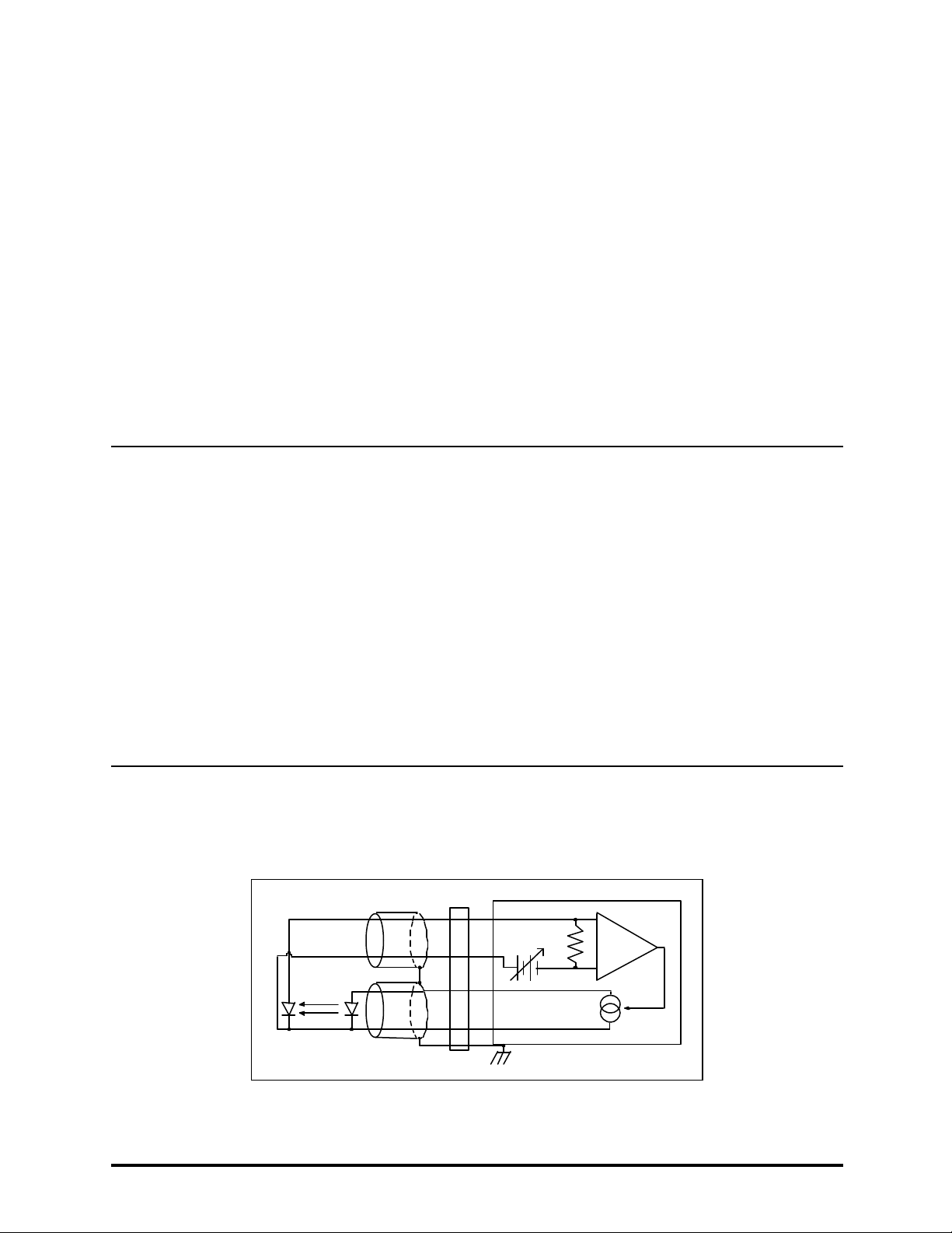
It is also recommended that the connections to the LDC-3916338 Laser Diode Controller module output be made
using twisted wire pairs with an earth-grounded shield (see Figures 2.1 A - D). We recommend using our CC-305S or
shorter CC-315S Shielded Laser Cable which are unique twisted-pair cables with braided outer shield designed to
provide the best possible rejection of most transient noise signals. The output terminals of the instrument are left
floating relative to earth ground to suppress AC power-on/power-off transients that may occur through an earth-
ground path. If the output circuit is earth-grounded at some point (such as through the laser package and mount),
the user must be careful to avoid multiple earth grounds in the circuit. Multiple earth grounds may provide circuit
paths that induce spurious currents in the photodiode feedback circuit and output leads.
NOTE
Experience indicates that should an inadvertent open circuit occur during laser operation
(while the LASER is ON), your laser may be damaged by a momentary circuit break-and-remake
before the final circuit break. Your new LDC-3916338 Controller Module has circuitry designed
to detect open circuits and will shut the output off under most conditions. However, we
recommend that cable connections to the laser be secure enough that they won't open-circuit,
should they be jostled or bumped.
Use appropriately shielded cabling to reduce coupling of potentially laser damaging transients.
Do not “bundle” the current source cables with other cables in your system or laboratory. See
Application Note #3, “Laser Diode Protection Strategies” for more detailed discussions on
connecting to your laser.
Figures 2.1 A - D show the possible configurations of connecting laser diodes and photodiodes with the
LDC-3916338 Module.
+
-
+Bias
Module
OUTPUT
7
6
9
5
3
P. D. L. D.
Earth Ground
Figure 2.1 A Common Laser Cathode - Photodiode Cathode
Artisan Technology Group - Quality Instrumentation ... Guaranteed | (888) 88-SOURCE | www.artisantg.com
HOW TO OPERATE YOUR LDC-3916338 3.0 AMP CURRENT SOURCE MODULE CHPT 2
PAGE 3
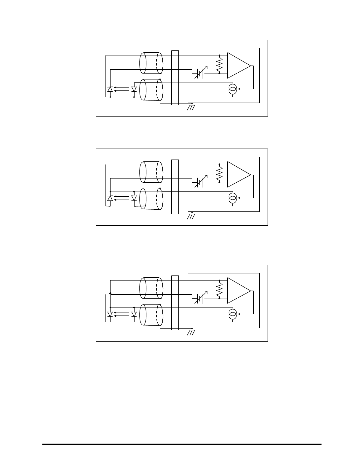
+
-
+Bias
Module
OUTPUT
7
6
9
5
3
P. D. L. D.
Earth Ground
Figure 2.1 B Common Laser Cathode - Photodiode Anode
+
-
+Bias
Module
OUTPUT
7
6
9
5
3
P. D. L. D.
Earth Ground
Figure 2.1 C Common Laser Anode - Photodiode Cathode
+
-
+Bias
Module
OUTPUT
7
6
9
5
3
P. D. L. D.
Earth Ground
Figure 2.1 D Common Laser Anode - Photodiode Anode
The 9-pin connector on the rear panel (bottom connector) of your Current Source Module is used to connect your
laser diode to the current source. There are connections provided for laser cathode and anode, photodiode cathode
and anode, chassis ground, interlock, and laser forward voltage. The pin-out diagram for this connector is shown in
Figure 2.2.
Artisan Technology Group - Quality Instrumentation ... Guaranteed | (888) 88-SOURCE | www.artisantg.com
Table of contents
Other ILX Lightwave Control Unit manuals

Popular Control Unit manuals by other brands


ANTUMBRA
ANTUMBRA BANK Building instructions

Radwin
Radwin AP0127730 reference guide

Wiesner Hager
Wiesner Hager furniloop Assembly instructions/Operating instructions

Tescom
Tescom SG 1 Series Instructions for use

FireAngel
FireAngel WTSL-SN-1 Installation and user guide

Bentel Security
Bentel Security Absoluta ABS-IP Installer manual