SEV User Manual
Version: 02/05/2021
15
6. FLOW SENSOR AND SOLENOID ADJUSTMENTS
Adjustment of solenoid power levels A and C (already factory adjusted)
The adjust ent of the solenoid power level is necessary if parts of the solenoids have been changed during
servicing. Solenoid power level has to be adjusted to ensure the valves best possible perfor ance and to
produce a quick and s ooth initial ove ent of the car away fro the floor. The travel direction is shown by
the color of the LEDs. Green LEDs are referring to Up direction while red LEDs are used for Down direction.
Within the “MAIN MENU” and the “Status”, the
digital value of the UP solenoid (A) or DOWN
solenoid (C) during an UP or DOWN travel is
displayed. Depending on travel direction, the
green LED for output signal A (Up) or red LED
for output signal C (Down) will be illu inated.
The digital value should be around 2100 ± 200
during constant travel while in full speed or
slow speed. Setting up this value is easier done
while travelling with slow speed since there is
ore ti e for adjusting. To alter the value, turn
the tri screw in or out. Turn clockwise to
increase digital value. Turn counter clockwise
to decrease digital value.
Adjustment of flow sensor
Attention!
Flow sensor is already factory adjusted. Readjusting is only necessary when replacing sensors.
Vertical sensor adjust ent
If the sensor value [ A] under static condition is not set between 4.8 and 5.3 A, close the ball valve and
open anual lowering to drop the valve pressure, loosen up the lock screw of the sensor and turn the
knurled sensor-head in or out until the value is between 4.8 and 5.3 A. Re-tighten the lock screw.
Attention: Adjusting the sensor value below 4.5 A ay cause the
sensor to press against the flow eter!
Radial sensor adjust ent
For radial adjust ent of the sensor loosen the bushing lock
nut (4), without turning the sensor bushing (2). Operate the
elevator to run Up and Down at leveling speed. Measure
the speed with stop watch or tacho eter. Levelling speeds
for both directions should have the sa e value. If Down
leveling speed is slower than Up leveling speed, rotate the
bushing (2) clockwise by 15° and re- easure the leveling
speeds. If Down leveling speed is faster than Up leveling
speed, rotate the bushing (2) counter-clockwise by 15° and
re- easure the leveling speeds.
Repeat the process of rotating the bushing in clockwise or
anti-clockwise as required to set the Up and Down leveling
speeds to be practically the sa e. Re-tighten the bushing
lock nut once the setup is finished.
1 Sensor head
2 Sensor bushing
[19 (3/4”) spanner]
3 Sensor lock screw
(3 Allen key)
4 Bushing lock nut
[32 (1 1/4”) spanner]
1
2
3
4
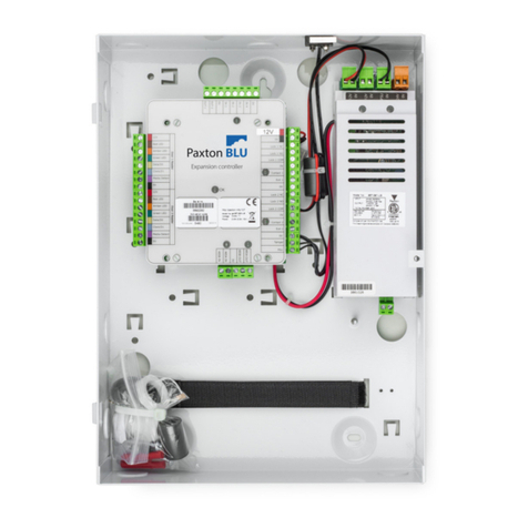
Tri screws at
solenoids A and C
(3 Allen key)


