Blain Hydraulics SEV User manual

Smart Servo Electronic Valve manual

SEV User Manual
Version: 02/2020
2
Copyright ©2020
Blain Hydraulics GmbH
All rights reserved. No part of this manual may e reproduced, stored in a retrieval system, or transmitted, in
any form, or y any means, mechanical, electronic, photocopying, recording, or otherwise, without the prior
written permission of Blain Hydraulics.
Moreover, Blain Hydraulics reserves the right to change the information contained in this manual without any
notice
Every precaution has een taken in the preparation of this manual. Nevertheless, Blain Hydraulics assumes
no responsi ility for damages resulting from the misuse of the information contained in this pu lication
For support please contact
Technical support
Sales
Pfaffenstrasse 1
74078 Heil ronn, Germany
Tel: +49-7131-282132 | Fax: +49-7131-282199
Email: info@ lain.de | www. lain.de
Pfaffenstrasse 1
74078 Heil ronn, Germany
Tel: +49-7131-28210 | Fax: +49-7131-282199
Email: info@ lain.de | www. lain.de

SEV User Manual
Version: 02/2020
3
TABLE OF CONTENTS
1.
General information ..................................................................................................................................... 4
1.1
Safety precautions & general warnings .............................................................................................. 4
1.2
Product introduction ............................................................................................................................ 4
1.3
Waranty information ........................................................................................................................... 4
2.
The SEV card .............................................................................................................................................. 5
2.1
LED Diagnostics ................................................................................................................................. 6
3.
The SEV valve ............................................................................................................................................. 7
3.1
Valve operation ................................................................................................................................. 10
4.
Electrical installation .................................................................................................................................. 12
5.
Control valve installation ........................................................................................................................... 13
6.
Flow sensor and solenoid adjustments ..................................................................................................... 14
7.
Wi-Fi connectivity & security ..................................................................................................................... 15
8.
Setup procedure ........................................................................................................................................ 16
8.1
Software menu overview .................................................................................................................. 16
8.2
Main menu ........................................................................................................................................ 17
8.3
Update .............................................................................................................................................. 25
9.
Errors ......................................................................................................................................................... 26
10.
Monitoring .................................................................................................................................................. 27
11.
Selection charts – valve inserts ................................................................................................................. 29
12.
Trou leshooting ......................................................................................................................................... 30
12.1
General errors................................................................................................................................... 30
12.2
Up direction travel ............................................................................................................................. 31
12.3
Down direction travel ........................................................................................................................ 32
13.
Flow – pressure chart (metric & imperial) ................................................................................................. 33

SEV User Manual
Version: 02/2020
4
1. GENERAL INFORMATION
1.1 SAFETY PRECAUTIONS & GENERAL WARNINGS
Installation, operation and servicing of the SEV
should only e performed y qualified
personnel. Before installing the SEV package,
the " uick Start Guide" should e read,
understood, and all safety precautions
mentioned in these documents and warnings
must e followed. The SEV must e installed
according to the descriptions in this technical
manual and in accordance with the local
elevator safety codes and directives.
1.2 PRODUCT INTRODUCTION
The SEV package consists of:
1) SEV valve
2) Electronic card
3) User manual
The valve: The smart servo electronic valve has een integrated with a pressure and temperature sensor
alongside a flow meter. The intelligent design has een further improvised y removing some adjustments to
simplify and quicken the set-up process. Integration of pressure and temperature sensors ena le excellent
ride quality y providing real time compensation to pressure and temperature changes.
The smart electronic card: The on oard we server and Wi-Fi on the electronic card allows users with any
Smart phone, Ta let, Laptop or PC having Wi-Fi connection possi ilities to connect with the card and set-up
the system, make changes or even see the travel graphs of the elevator. The platform is system independent
and can e accessed using any standard we rowser independent of the operating system of the device used
for interacting with the card. The Wi-Fi connectivity makes it very easy to use any smart device for set-up, fine
tuning and real time monitoring from a distance without the hassle of using different ca les and compati le
devices in a machine room. Since the complete system is platform independent, there is no need to download
and install any app or software. The em edded software on electronic card stores all the settings, information
and travel logs. The set- y-step set up guide and multilingual interface software in SI and Imperial units make
inputting and monitoring information very easy.
1.3 WARANTY INFORMATION
Blain's SEV User Manual is provided for qualified personnel, who are competent in installing, adjusting and
servicing of hydraulic elevators. Blain Hydraulics assumes no lia ility for any personal injury, property damage,
losses or claims arising from in appropriate use of its product or incompetence of the installer.
Warranty expires, if:
Components or spare parts different than the original ones are installed.
Elevator system or SEV is installed or serviced y unqualified personnel.
SEV package is installed in any location without applying the elevator safety codes (EN81-20/50,
ASME 17.1 or the existing local code).
Figure 1: Smart Servo Electronic Valve

SEV User Manual
Version: 02/2020
5
2. THE SEV CARD
A Mode switch I Input signals
B Memory card slot J Output signals
C Jumper for data upload K Error relay
D Type plate L Power supply 24 V DC / 18 V AC
E Flow sensor adjustment feed ack M Error / warning LED
F Temperature sensor connection N Power LED
G Pressure sensor connection O Quit / confirm utton
H Flow sensor connection P Spot for additional interface PCB
Blain 000000
SEV07 - 0000
C
O
L
K
A
B
E
D
F
G
H
I
J
M
N
P

SEV User Manual
Version: 02/2020
6
2.1 LED DIAGNOSTICS
SWITCH LED
If switch “1” is in „ON“-
position, the LED will
flash slowly. Once a
connection to a smart
device is esta lished,
the LED glows
continuously.
POWER LED
The green power LED
will continuously glow
as long as the
electronic card is
supplied with power.
INPUT AND OUTPUT SIGNAL LEDs
D (red), C (red), B (green), A (green) and Ins
(yellow) are reflecting the input signals into
the electronic card.
Down (red) and Up (green) are the
corresponding output signals and indicate the
travel direction.
BOOT LOADER LEDs
If the jumper is set in
non- ridged mode, the
green and red LED will
light up alternately.
Setting the jumper in
ridged mode causes
the red LED to glow
continuously and the
green LED to flash
slowly. If an update is
eing processed, the
green LED will flash
rapidly until the update
is finished.
Green
Red
STATE LED
The orange state LED flashes
slowly. Any other ehaviour is
related to communication
pro lems and reflects a defect.
FLOW LEDs
They indicate if the
sensor has een
adjusted properly. If
the adjustment is set
higher or lower than
the range, the
corresponding LEDs
will light up to signal,
that the sensor has to
e readjusted.
SENSOR LEDs
These will glow green if
the pressure-
temperature sensor is
connected properly.
Orange
Red
DIAGNOSTIC LEDs
The orange “Warning”
LED lights up in case
of an unexpected
ehaviour. If there is a
major fault interfering
with the normal
operation of the valve
like the flow sensor or
a coil eing defect, the
“Error” LED will light
up and prevent the
SEV from functioning
until the error has
een quit with the help
of the “OK” utton.

SEV User Manual
Version: 02/2020
7
3. THE SEV VALVE
The Blain Servo Electronic Valve (SEV) is controlled y closed loop digital electronics, providing
consistent acceleration and deceleration of hydraulic elevators largely independent of load and
oil temperature. An electronic card regulates the performance of the car via proportional solenoid
valves. The elevator operation can e monitored, recorded and adjusted y a smart device using
Wi-Fi connectivity. Additional intermediate speed for maintenance runs can also e programmed.
Figure 2: SEV valve sizes
SEV valves include the following essential features:
Self-cleaning pilot line filters Temperature and pressure compensation
Self-cleaning main line filter (Z-T) Built-in tur ulence suppressors
70HRc hardened ore surfaces Pressure gauge and shut off cock
100% continuous duty solenoids Self-closing manual lowering
Technical data
1” SEV
1½” SEV
2” SEV
Flow range l/min
(USgpm)
40-180
(10-48)
-430
(-114)
-580
(-153)
Pressure range ar (psi) 9-70 (130-1000)
Burst
p
ressure
ar (psi) 400 (5750)
Pressure loss
(static)
ar
(psi)
≈ 2 – 3 ar (29 – 44 psi)
depending on flow and valve port size
Weight
kg (l s) 10 (22)
Oil viscosity 22-75 cSt. at 40°C (104°F)
Max. oil t
emperature
14°-61°C (57°-142°F) for oil VG46; 200 cSt – 20 cSt.
Optimal
oil t
emperature
25°-50°C (77°-122°F) for oil VG46; 100 cSt – 30 cSt.
Ambient temp range 0°-70°C (32°-158°F)
Insulation c
lass, AC and DC
IP 68
Coils
AC
24 V/1.8 A, 42 V/1.0 A, 110 V/0.43 A, 230 V/0.18 A
Coils DC
12 V/2.0 A, 24 V/1.1 A, 42 V/0.5 A, 48 V/0.6 A, 80 V/0.3 A, 110 V/0.25 A,
196 V/0.14 A
Elec.
c
ard
i
nput
24 V DC / 18 V AC
Elec. card w
eight
0.5 Kg (1.1 l s)
Up travel Up to 1.0 m/s (197 fpm). 1 Full Speed, 1 Leveling Speed, 1 Inspection speed.
Down travel Up to 1.0 m/s (197 fpm). 1 Full Speed, 1 Leveling Speed, 1 Inspection speed.

SEV User Manual
Version: 02/2020
8
Figure 3: SEV valve dimensions
Optional Equipment
EN Emergency coil DH High pressure switch
CSA CSA coils DL Low pressure switch
KS Slack rope valve BV Ball valve
HP Hand pump HX/MX Auxiliary down valve
Figure 4: Hydraulic circuit
Control Elements
Down adjustments
C Solenoid Down control U Bypass valve 7 Full speed limitation
D Solenoid Down start/stop V Check valve 9 Manual lowering speed
H Manual lowering X Down valve
S Pressure relief valve Y Down leveling valve
1” SEV
1½” SEV 2” SEV

SEV User Manual
Version: 02/2020
9
Ca in
Q
I
pT
T
P
9 7
H S
A
C D
Control elements
A Solenoid Up control I Flow sensor V Check valve
C Solenoid Down control pT Pressure-temp.-sensor X Down valve
D Solenoid Down start/stop Flow meter Y Manual lowering valve
E Short delay valve R Flow ring 2 Pilot orifice Up
F Filter S Pressure relief valve 8 Pilot orifice Down
H Manual lowering U Bypass valve
R
E
Horizontal
section
Vertical
section
Z
8 2
X
V
U
Y
CT
AT
D C A
8 2
S
H
F
XC
UC
Figure 5: ut section view of the SEV valve
Cylinder
Connections
P Pump port
T Tank port
Z Cylinder port
Pilot pressure chambers
UC Bypass cham er
XC Down valve cham er
Adjustment UP
AT Up trim (page 13)
Adjustments DOWN
CT Down trim (page 13)
7 Full speed limitation
9 Manual lowering speed

SEV User Manual
Version: 02/2020
10
3.1 VALVE OPERATION
UP operation
1. With an Up signal, the pump-motor is energized and the electronic card´s Up program starts
simultaneously. Oil flows through orifice 2 into the ypass pilot cham er UC.
2. Coil A is energized and solenoid A (normally open) from the card and partially closes, reducing
the volume of pilot oil flowing out from the ypass pilot cham er.
3. The ypass valve U egins to close as pressure increases in the ypass pilot cham er. As the
ypass valve U closes, the check valve V egins to open as a steadily increasing volume of oil
flows into the cylinder of the elevator, displacing the flow meter .
4. The inductive flow sensor I, measures the increasing displacement of the flow meter. This value
is compared in the card with the target flow value, which prescri es the acceleration, full speed,
deceleration and levelling speed of the car. Correction of the measured flow rate is made y
varying the power from the card to coil A, controlling the position of the ypass valve through
pilot pressure in cham er UC.
5. The comparison and correction of the measured flow to target flow values, continue throughout
the complete Up operation of the elevator.
DOWN operation
(Caution! Voltage for coil D comes directly from the elevator´s controller, not from the SEV
card)
6. With a Down signal, coil D is energized, solenoid D (normally closed) opens and the electronic
card´s Down program starts simultaneously.
7. Coil C is energized from the card and solenoid C (normally closed) partially opens allowing oil
to pass through fixed orifice 8 escaping from the down valve pilot cham er XC through solenoid
D (fully open) ack to tank.
8. The down valve X egins to open as pressure decreases in the down valve pilot cham er XC.
As the down valve opens, a steadily increasing volume of oil flows from the elevator´s cylinder
into the tank, displacing the flow meter .
9. The inductive sensor I measures the increasing displacement of the flow meter. This value is
eing compared y the card with the set value of the target flow.
10. Correction of the measured flow rate is made y variation of power from the card to coil C
controlling the position of the down valve through pilot pressure in cham er XC.
11. The comparison and correction of the measured flow to target flow values continue throughout
the complete Down operation of the elevator.

SEV User Manual
Version: 02/2020
11
Inspection Speed
Besides full speed and levelling speed, an optional inspection speed is included in the electronic
card´s software. Up and down inspection speeds can e independently adjusted etween 0.05 m/s
and 0.30 m/s.
Valves are already adjusted and tested. Check electrical operation efore changing valve settings.
Test that the correct coil is energized y removing the nut and raising the coil slightly to feel magnetic
pull.
S Pressure relief valve: Turning it ‘In’ (clockwise) produces a higher, ‘out’ (c-clockwise) a lower
maximum pressure setting. After turning out, open manual lowering H for an instant to release
pressure inside the valve.
Important: When testing the pressure relief valve, do not close ball valve sharply.
KS Slack rope valve: Coils C and D must e de-energized! The KS is adjusted with a 3 mm Allen
key. Turning the screw K ‘in’ results in a higher pressure setting and ‘out’ in a lower pressure setting.
To adjust, turn K all the way ‘in’, then turn K ‘out’ until the empty car just egins to descend, then
turn out another half a turn to ensure that with cold oil the empty car can e lowered as required.
Figure 6: SEV adjustments and explosion drawing
Adjustments Highlighted valve parts
CT Trim solenoid C H Manual lowering
S Pressure relief valve X Down valve
AT Trim solenoid A Y Down levelling valve
KS Slack rope valve V Check valve
9 Manual lowering speed U Bypass valve
7 Maximum speed
limitation
KS 9 7
CT S AT
SEV User Manual
Version: 02/2020
12
1 2 3 4 5 6 7 8 9 10 11 12 13 16 17 18
19 20
21
22
23
24
25
Voltage
for
coil D
Lift Controller SEV card
R1
Card internal relay
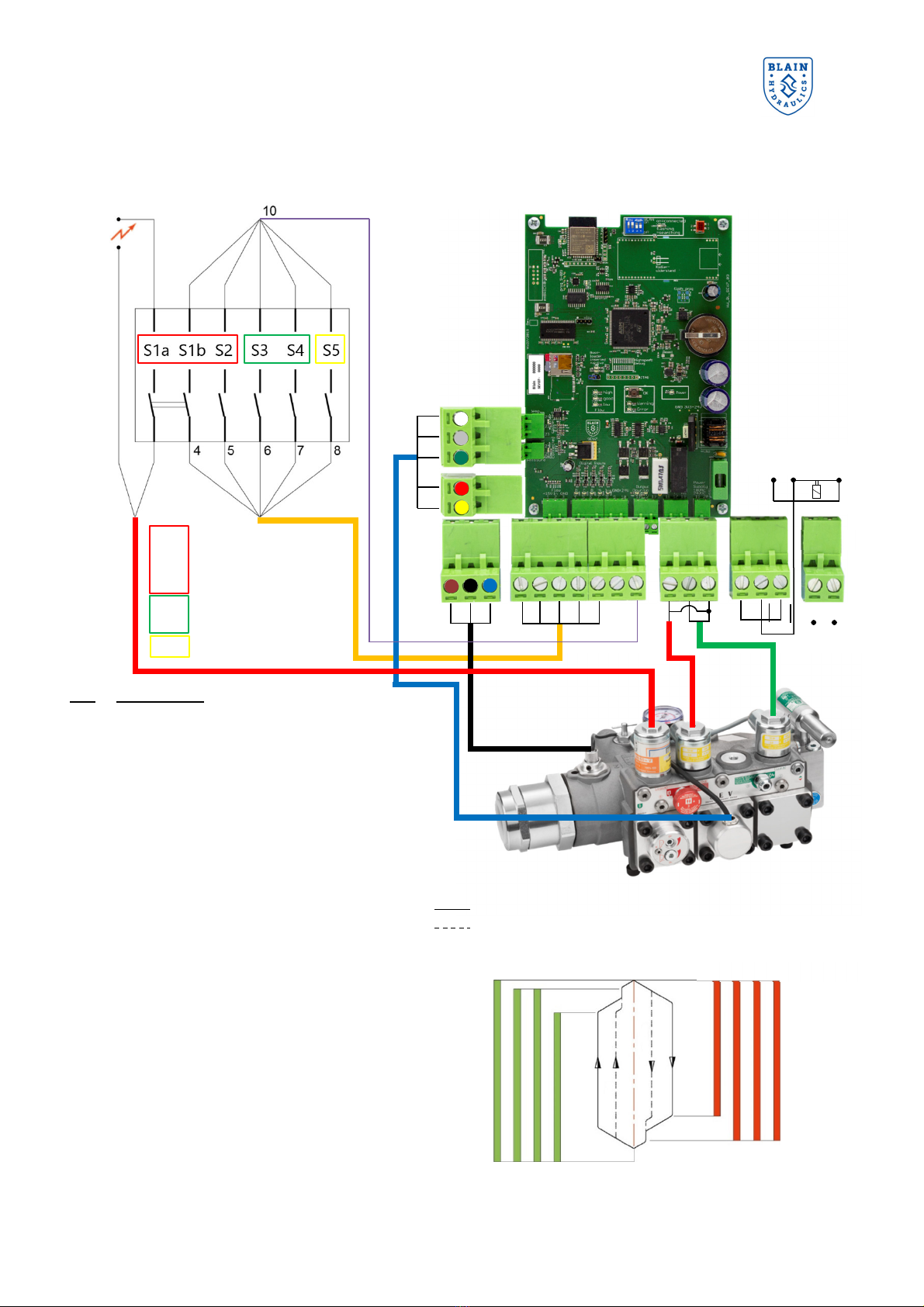
4. ELECTRICAL INSTALLATION
PIN Explanation
1 Power supply 15 V ( rown wire)
2 Sensor signal ( lack wire)
3 Neutral ( lue wire)
4 Input signal "S1 " Down start/stop – D
5 Input Signal "S2" Down control – C
6 Input signal "S3" Up full speed – B
7 Input signal "S4" Up control – A
8 Input signal "S5" inspection – I
9 Input signal neutral (ext. supply)
10 Input signal 24 V DC
11 Output signal "C" Up
12 Output signal "A" Down
13 Output signal neutral for Up and Down
16 Error relay NC – closed if OK – open if fault
17 Error relay COM
18 Error relay NO – open if OK – closed if fault
19 Supply voltage ground
20 Supply voltage live 18V AC / 24V DC
21 PT100 C (white wire)
22 PT100 B (grey wire)
23 PT100 A (green wire)
24 24 V (red wire)
25 4-20 mA (yellow wire)
S1a Down levelling (coil D)
S1 Down levelling
S2 Down full speed
S3 Up full speed
S4 Up levelling
S5 Inspection
24 V DC
18
V AC
Electrical travel
Sequence UP DOWN
Normal travel: S3+S4 S1a+S1 +S2
Inspection: S3+S4+S5 S1a+S1 +S2+S5
Slow speed: S4 S1a+S1
S5 S4 S3
Motor
S2 S5 S1b S1a (coil D

SEV User Manual
Version: 02/2020
13
5. CONTROL VALVE INSTALLATION
Check the following:
1. The flow on the data plate of the valve complies with the flow rate of the pump (±10 %).
2. The minimum and maximum static pressures on the valve data plate is in accordance with those of the
elevator.
3. The electrical supply to the SEV card is 24 VDC / 18 VAC and 50 VA.
4. The star delta timer is set to etween 0.3 and 0.4 secs.
5. The flow ring R, ypass valve U and down valve X are correct using chart A at rear of the hand ook.
6. The flow sensor is adjusted etween 4.8 and 5.3 mA
Installation of the SEV Valve onto the Power Unit
For a compact and time saving installation as well as easier servicing and protection of the flow meter, cylinder
connection Z of the SEV is fitted with the Blain all valve G1“, 1.5“, 2“or 2.5“.
Installation of the SEV Card into the Controller
The SEV Card can e connected into any standard type hydraulic elevator controller. The power to coils A and
C is supplied from the card. Power to coil D is directly provided y the main controller. Page 11, shows the
detailed wiring diagram for connecting the SEV card to the elevator controller.
Installation of Deceleration Switches in the Elevator Shaft
Slow-down (deceleration) and stop switches should e set according to the following recommendations
Recommended switch positions and levelling speeds
Metric
Imperial
Travel
speed
Decel.
switch
before floor
Levelling
speed
Stop
switch
before
floor
Travel
speed
Decel.
switch
before
floor
Levelling
speed
Stop
switch
before
floor
m/s
cm
m/s
cm
ftm
i
n
f
t
m
in
0.3 25 0.06 1.0 60 10 12 0.4
0.4 45 0.06 1.0 80 17 12 0.4
0.5 60 0.06 1.0 100 24 12 0.4
0.6 75 0.06 1.0 120 30 12 0.4
0.7 95 0.07 1.5 140 37 14 0.6
0.8 110 0.07 1.5 160 43 14 0.6
0.9 130 0.08 2.0 180 51 16 0.8
1.0 145 0.08 2.0 200 57 16 0.8
Depending on customers priorities, for travelling time or stopping accuracy, the recommended values for
levelling speeds may e modified, i.e. for faster floor to floor times; faster levelling speeds, for more accurate
floor stops; slower levelling speeds.
SEV User Manual
Version: 02/2020
14
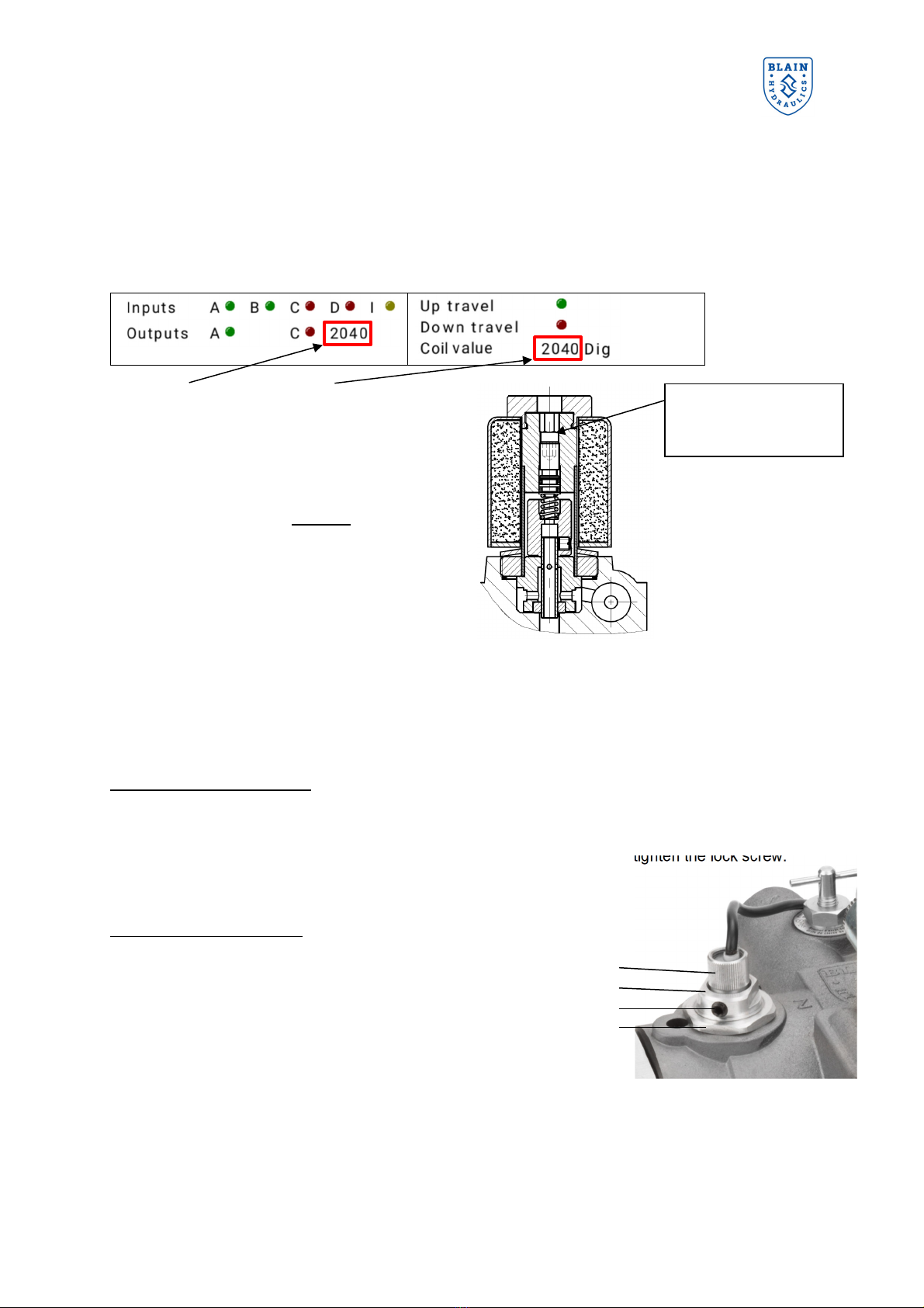
6. FLOW SENSOR AND SOLENOID ADJUSTMENTS
Adjustment of solenoid power levels A and C (already factory adjusted)
The adjustment of the solenoid power level is necessary if parts of the solenoids have een changed during
servicing. Solenoid power level has to e adjusted to ensure the valves est possi le performance and to
produce a quick and smooth initial movement of the car away from the floor. The travel direction is shown y
the color of the LEDs. Green LEDs are referring to Up direction while red LEDs are used for Down direction.
The “MAIN MENU” and the “Status” are
showing the digital value of the UP solenoid
(A) or DOWN solenoid (C) during an UP or
DOWN travel. Depending on travel direction,
the green LED for output signal A (Up) or red
LED for output signal C (Down) will e
illuminated. The digital value should e
around 2100 ± 200 during constant travel
while in full speed or slow speed. Setting up
this value is easier done while travelling with
slow speed since there is more time for
adjusting. To alter the value, turn the trim
screw in or out. Turn clockwise to increase
digital value. Turn counter clockwise to
decrease digital value.
Adjustment of flow sensor
Attention!
Flow sensor is already factory adjusted. Readjusting should only e necessary when replacing sensors.
Vertical sensor adjustment
If the sensor value [mA] under static condition is not etween 4,8 and 5,3 mA, close the all valve and open
manual lowering to make the valve pressure-less, loosen up the lock screw of the sensor and turn the
knurled sensor-head in or out until the value is etween 4,8 and 5,3 mA. Re-tighten the lock screw.
Adjusting the sensor value elow 4.5 mA may cause the sensor to
press against the flow meter
.
Radial sensor adjustment
For radial adjustment of the sensor loosen the ushing lock
nut (4), without turning the sensor ushing (2). Operate the
elevator to run Up and Down at leveling speed. Measure
the speed with stop watch or tachometer. Levelling speeds
for oth directions should have the same value. If Down
leveling speed is slower than Up leveling speed, rotate the
ushing (2) clockwise y 15° and re-measure the leveling
speeds. If Down leveling speed is faster than Up leveling
speed, rotate the ushing (2) counter-clockwise y 15° and
re-measure the leveling speeds.
Repeat the process of rotating the ushing in clockwise or
anti-clockwise as required to set the Up and Down leveling
speeds to e practically the same. Re-tighten the ushing
lock nut once the setup is finished.
1 Sensor head
2 Sensor ushing
[19 mm (3/4”) spanner]
3 Sensor lock screw
(3mm Allen key)
4 Bushing lock nut
[32 mm (1 1/4”) spanner]
1
2
3
4
Trim screws AT and
CT at solenoids A and
C (3mm Allen key)

SEV User Manual
Version: 02/2020
15
. WI-FI CONNECTIVITY & SECURITY
The SEV electronic card uses the IEEE Standard 2.4GHz, 802.11 /g/n connectivity protocols. Generally, all
modern-day smart devices (phone/ta let/laptop) can communicate with the Wi-Fi access point on the card
using these protocols. The SEV card is delivered using the default settings as shown in the picture elow.
Switch 1 - The Wi-Fi switch in ON position allows
communication with the electronic card using a smart
phone. The on- oard Wi-Fi access point is availa le for
accepting connections.
Switch 2 – OFF position allows ackward compati ility of
the electronic card to e used for the older version of the
SEV valve. Certain functions related to pressure and
temperature measurements are not availa le.
Switch 3 & 4 – Reserved for Blain Hydraulics.
To connect with the SEV card using your smart device,
ensure the switch 1 to e in ON position. The Blue
LED will flash during the process of esta lishing a Wi-
Fi connection. Once a sta le connection is esta lished,
the LED would stop flashing and remain ON.
Getting connected
1
2
3
4
Identify and connect
with the BLAIN-SEV
Wi-Fi from your smart
device.
Provide the password to
get connected. The
default password is
12345678
Once connected, tap on
the Wi-Fi to get into the
configuration. Tap on
“Manage router” to enter
the on- oard APP on
the access point in your
preferred rowser
(Firefox recommended).
Alternatively open your
preferred rowser and
provide the IP address
192.168.4.1 in the
navigation ar.
Once the authentication
is completed, a loading
screen will appear and
confirm the successful
connection. Once
loading is completed the
MAIN MENU can e
seen.
During the time the smart device is connected
with the SEV card, no internet connectivity or
other network connections are possible.
In order to safeguard unauthorized access to the
i-Fi and the electronic card, the i-Fi should
be switched OFF on completion of setup /
configuration / monitoring.

SEV User Manual
Version: 02/2020
16
8. SETUP PROCEDURE
8.1 SOFTWARE MENU OVERVIEW
Language
1. German
2. English
3. Spanish
Settings
1. Date / Time Set date and time
2. Units SI
Imperial
3. Valve settings
Gain value
Dither amplifier
Speed mode
Pressure relief valve
4. Factory settings
Reset elevator data
Reset travel data
Reset all data to
factory settings
5. Wi-Fi settings
IP Adress
SSID
Password
6. Pro
Save factory setting
Sensor cali ration
Sensor ta le
Device ID
Hardware ID
State
Notifications
1. State
2. Notifications
3. Update
Install wizard
1. Welcome screen
Introduction
2. Cylinder data
Transmission
No. of cylinders
Piston type / diameters
3. Pump data Performance
Efficiency
4. Weight &
pressure
Empty ca in
Payload
Min. pressure
Max. pressure
5. Up travel data
Speed
Acceleration
Soft stop
6. Down travel data
Speed
Acceleration
7. Inspection travel
data
Up travel
Down travel
8. Final screen Final information
Data collection
1. Elevator data
Cylinder data
Pump data
Weight
Pressure
2. Travel data
Up travel
Down travel
Inspection travel
3. Teach run /
speed adjustment
Teach values
Standard values
R10 Test
4. Log ook Last runs
Reset counters
5. Trou le shooting
General error
Error Up travel
Error Down travel
Ⅱ
Ⅰ
Ⅳ
Ⅴ
Ⅲ

SEV User Manual
Version: 02/2020
17
8.2 MAIN MENU
The language of the software can e changed y
pressing the flag in the upper left corner. From the
main menu the easy to use “Install wizard” for
assisting during initial setup, the “Data collection”,
“Settings” and “State/Notifications” su menus
can e accessed.
Once the preferred language has een selected, go
to “Settings” to set the date and time and choose
your units for setting up the valve. In order to set up
the valve, please follow the instructions. Use the
“Main Menu utton” (highlighted) to get ack to the
“
MAIN MENU
”.
The following chapter of this installation manual descri es how to set up and service the valve with the help
of the software. The most important points of navigating the menu will e covered and the su menus “Install
wizard”, “Data collection”, “Settings” and “State / Notifications” will e explained in detail.
As the software for interacting with the SEV card resides on the we server and on the card itself, no additional
software installation on the smart device is necessary. This unique feature allows the user to use any smart
device; independent of the operating system or software architecture. It is highly recommended to use Mozilla
Firefox for Android or Safari for iOS as we rowsers.
Before the installation wizard is started it is highly recommended that all technical data of the lift is readily
available and that the input unit is correctly selected. The choice for unit’s selection between Metric and
Imperial can be made from the “Settings” menu > units from the home screen.
I II
Main Menu utton

SEV User Manual
Version: 02/2020
18
The “MAIN MENU” allows access to the “Install wizard”, the “Data
collection”, the “Settings” and the “State/notifications” su menus.
The “Install wizard” is eing used to assist during valve setup and
serves as a step y step guide to help users entering the complete and
correct necessary elevator data.
The “Data collection” gives an overview a out all entered data to
make changes if necessary and it gives access to the “Logbook” and
the “Trouble shooting” sections.
In the “Settings” menu you can change units, valve and Wi-Fi settings
or reset settings to factory settings if desired.
The “State/notifications” shows the status of the system and allows
for possi le updates.
The “Access” utton gives the user the possi ility to enter and change
passwords necessary for accessing the features of the software.
Furthermore the “MAIN MENU” acts as the first tool for analyzing and
setting up the valve. Values for pressure, temperature and flow are
displayed. In case of no readings the connections need to e
rechecked or the sensors changed. LEDs for input and output give
feed ack for diagnostics.
While traveling constantly in full speed or levelling speed in Up or
Down direction, the highlighted digital value should stay in the range of
2100 ± 200. The green check marks should show up ehind the digital
values of the solenoids giving feed ack of the correct starting values.
←Left
After starting the install wizard and
reading the welcome screen, you
are asked to enter the necessary
cylinder data. Pressing the uttons
for the different piston types will
ring up a dialogue field (screen on
the right), where the desired values
can e entered. To change
transmission ratio or num er of
cylinders, press the corresponding
values.
The effective piston diameter is
eing calculated depending on the
entered data. Changing its value
will override all other data. Press
confirm to continue the setup.
Right→
Select a piston type and enter its
diameters y touching the values.
Use the confirm utton on the
ottom right to get ack to the
screen on the left.
I
IV.2 IV.2c
DIGITAL VALUE
CHECK MARKS

SEV User Manual
Version: 02/2020
19
←Left
Enter the pump performance data
provided y the manufacturer. Due
to changes in load and oil viscosity
the pump will not always deliver its
full flow. Furthermore some flow is
needed y the SEV to regulate and
provide constant speed and travel
time. 90 % efficiency is an
approximated value.
Right→
Provide the static weight of your
elevator system and the pay load
data. Alternatively the values for
minimum and maximum pressure
can e entered. Please note that
entering the weight would
automatically calculate the pressure
and vice versa.
←Left and Right→
Enter your desired speeds,
acceleration and deceleration times
of the Up travel as well as the Down
travel.
Your full speed in Up direction is
already eing calculated ased on
the entered piston and pump data.
Speed in Down direction is limited to
196,85ftm (1m/s). Values shown in
imperial units are displayed after
eing converted from Metric system
and therefore vary slightly from the
input value.
The soft stop setting controls the
final stopping into the landing zone
in the Up direction. Making it too soft
which means choosing a smaller
value may cause the elevator to
continue traveling and surpassing
the floor level.
IV.3 IV.4
IV.5 IV.6
IV.7 IV.8

SEV User Manual
Version: 02/2020
20
←
Left
The inspection travel speed for Up
and for Down direction can e set
here. Inspection speed is
sometimes referred to as the
second slow speed, which can e
used for inspections or short floor
distances. Press continue to
proceed further.
Right→
Once you reach the final screen,
the install wizard ends, confirming
that the entered data has een
saved successfully on the
electronic card. In order to review
all entered data, you can run the
install wizard again or check the
“Data collection”. Changes can e
made in the “Data collection” su
menu as well.
←Left
The “Data collection” su menu of
the software provides an overview
of the existing data stored on the
card. Data can e entered here
when selecting “Elevator data” or
“Travel data”. In addition there is
access to the “Teach run” menu,
the “Log book” as well as the
“Trouble shooting”. The “Teach
run” menu cali rates the flow
sensor while the “Logbook”
provides an overview of travel logs
with the option of looking at the
travel graph. “Troubleshooting”
offers help on general errors and
errors in Up and Down direction.
Right→
Within the “Elevator data” menu
section you can check the data for
your piston, pump, weight and
pressures and change them if
desired.
V V.1
IV.7 IV.8
Other manuals for SEV
1
Table of contents
Other Blain Hydraulics Control Unit manuals

Blain Hydraulics
Blain Hydraulics EV4 User manual

Blain Hydraulics
Blain Hydraulics SEV User manual

Blain Hydraulics
Blain Hydraulics R10 User manual

Blain Hydraulics
Blain Hydraulics L10 User manual

Blain Hydraulics
Blain Hydraulics EV100 Series User manual

Blain Hydraulics
Blain Hydraulics KV1P Guide

Blain Hydraulics
Blain Hydraulics SEV07 User manual

Blain Hydraulics
Blain Hydraulics EV100 Series User manual

Blain Hydraulics
Blain Hydraulics EV Series User manual


