BLAIN HYDRAULICS
Z1
DC
S
2
9
6
8
KS
M1
3
5
Y
X
H
VU
Z1 M1
D C
68
9 7
2
S
KS
3
5
A
B
Adjustments DOWN
6Down Acceleration
7Down Full Speed
8Down Deceleration
9Down Levelling Speed
Plugs
3
5
A
B
Adjustments DOWN
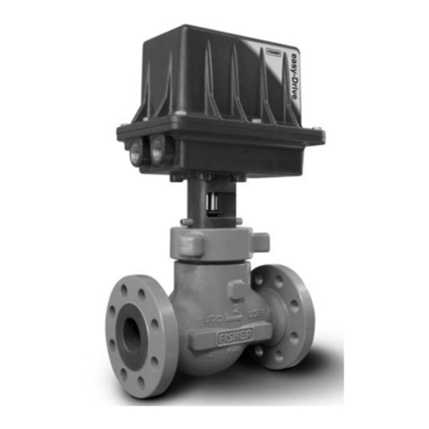
Control Elements
CSolenoid (Down Deceleration)
DSolenoid (Down Stop)
HManual Lowering
SRelief Valve
UBy Pass Valve
VCheck Valve
XFull Speed Valve (Down)
YLevelling Valve (Down)
2Fix Orifice
Valves are already adjusted and tested. Check electrical operation before changing valve settings. Test that the correct solenoid is
energised, by removing nut and raising solenoid slightly to feel pull.
Nominal Settings: Adjustments 7&9approx. level with flange face. Two turns in either direction may then be necessary. Adjust-
ments 6&8turn all the way 'in' (clockwise), then 1.5 turns 'out' (c-clockwise). One final turn in either direction may be necessary.
6. Down Acceleration: When solenoids Cand Dare energised, the car will accelerate downwards according to the setting of
adjustment 6. 'In' (clockwise) provides a softer down acceleration, 'out' (c-clockwise) a quicker acceleration.
7. Down Speed: With solenoids Cand Denergised as in 6above, the full down speed of the car is according to the setting of
adjustment 7. 'In' (clockwise) provides a slower down speed, 'out' (c-clockwise) a faster down speed.
8. Down Deceleration: When solenoid Cis de-energised whilst solenoid Dremains energised, the car will decelerate according to
the setting of adjustment 8. 'In' (clockwise) provides a softer deceleration, 'out' (c-clockwise) a quicker deceleration.
Attention: Do not close all the way in! Closing adjustment 8 completely (clockwise) may cause the car to fall on the buers.
9. Down Levelling: With solenoid Cde-energised and solenoid Denergised as in 8above, the car will proceed at its down levelling
speed according to the setting of adjustment 9. 'In' (clockwise) provides a slower, 'out' (c-clockwise) a faster down levelling speed.
Down Stop: When solenoid Dis de-energised with solenoid C remaining de-energised, the car will stop according to the setting
of adjustment 8and no further adjustment will be required.
KS Slack Rope Valve: Solenoids Cand Dmust be de-energised! The KS is adjusted with a 3 mm Allan Key by turning the screw K'in'
for higher pressure and 'out' for lower pressure. With Kturned all the way 'in', then half a turn back out, the unloaded car should
descend when Manual Lowering H is opened. Should the car not descend, Kmust be backed o until the car just begins to
descend, then backed o a further half turn to ensure that with cold oil, the car can be lowered as required.
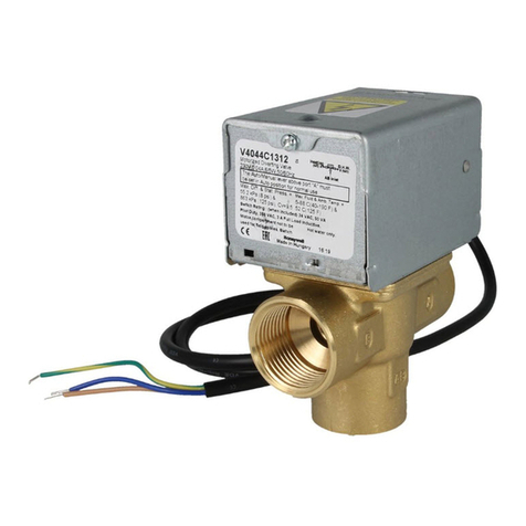
Warning: Only qualified personnel should adjust or service the EV4 valve and the L1000H drive. Unauthorised
manipulation may result in injury, loss of life or damage to equipment. Prior to servicing internal parts, ensure that
the electrical controller is switched o, cylinder line is closed and residual pressure in the valve is reduced to zero.
M1 Second pressure gauge connection, ½"
Z1 Pressure switch connection, ¼"
Important: Length of ¾" thread on pump
connections should not be longer than 14 mm!
Adjustments pressure relief valve
Valves are already checked for functionality. Check electrical operation before changing inverter settings. Please refer to the EV4
inverter manual for necessary parameter settings.
S Relief Valve: ‚In‘ (clockwise) produces a higher, ‚out‘ (c-clockwise) a lower maximum pressure setting. After turning ‚out‘, open
manual lowering Hfor an instant.
Important: When testing relief valve, do not close ball valve sharply.
Explosion


