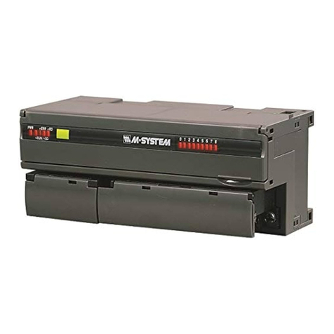
Blain Hydraulics R10 User manual

GmbH
AA
ZT
aG
30l
m
DK
o
an
p
a
G¼"
B
bG
b
DE
Ød
Øe
dM
eM
de
ØV
FV
f1
vf
2
fM
f3
F
R10 ½"
DK
G¹⁄ "
8
R 10 AA Standard
R 10 AA + Option (DK + ES)
R 10L AA
R 10L-R
R10
Examples •
5-2100 l/min
1,3-546 US gpm
5-2100 l/min
1,3-546 US gpm
B
Z
D
¾"- 3"
E
R10
D D E
EV100
T
B F0
Z
F
¾" - 3"
F
R10
F0F0F
EV100
T
E
Adaptor BE
Inch - mm
B - E
¾" - M36x2
1" - M36x2
1½" - M36x2
1" - M52x2
1½" - M52x2
2" - M52x2
1½" - M65x2
2" - M65x2
2" - M78x2
2½" - M78x2
B E
Pipe or hose
ES
Any connections 90°
L
R10L
in
V
G o.
NPT
M
52 x 2
Ød
d
Øe
e
28
26
M
52 x 2
M
36 x 2
M
36 x 2
M
52 x 2
M
65 x 2
M
52 x 2
42
44
28
26
42
44
42
26
42
44
56
40
56
44
kg
63
50
63
40
M
78 x 2
M
65 x 2
M
78 x 2
d
63
50
M
78 x 2 63
40
M
78 x 2
Recommended size •
1,05
26,7 38
1,5
1,5
1,5
1,5
1,5
1,5
38
38
38
38
38
1,31
1,90
2,37
2,87
3,50
33,4
48,3
60,3
73,0
88,9
ØV
in
ØV
mm Vmm
90°
Optional
I/min US gpm bar
EN81
psi
CSA
G o.
NPT
a b dM eM DN fM f1 f2 f3
5 - 100
50 - 175
100 - 425
250 - 800
700 - 1250
1200 - 2100
1,3 - 26
13 - 46
26 - 112
66 - 211
185 - 330
317 - 554
100
100
100
80
60
1150
1150
1350
950
880
690
¾''
1''
1½''
2''
2½''
3''
¾''
1''
1½''
2''
2½''
3''
18
21
26
28
30
34
32
35
38
45
45
32
19
25
38
51
64
76
M 10
M 10
M 12
M 12
M 12
M 16
36
38
44
45
50
50
47,6
52,4
70
77,8
89
106,4
22,2
26,2
35,7
42,9
50,8
62
105
105
143
167
196
240
62
62
94
108
121
149
50
50
60
80
100
120
11
11
11
20
19
22
11
11
11
17
18
21
(AA)
6
6
8
8
10
1,6
1,6
3,4
7
13
21
R10 R10 A B L D E F V
DK
Qc P max SAE Victaulic
l m n o p
Tube
4 - 90 1,0 - 23,8 100
100
1350 ½'' 18 88 53 40 9 11 6 0,9
6
Blain Hydraulics GmbH Tel.+49 7131 28210
Pfaenstrasse 1 Fax +49 7131 282199
74078 Heilbronn www.blain.de
Germany info@blain.de
Designer and Manufacturer of the highest
quality control valves &safety components
for hydraulic elevators
DK
EN ISO 9001
The rupture valve R10 can be
mounted in any position directly
onto the cylinder inlet connec-
tion Z. The 'T' port is connected to
the Tank. Fitted incorrectly the R10
valve will not function. The cylinder
side of the R10 can be identified by
locating a small orifice behind the
inside screw thread.
In the event of failure in the main
cylinder line or where the down
speed exceeds allowable limits, the
R10 valve closes, bringing the car
to a smooth stop.
GB
Warning: Only qualified personnel should service hydraulic valves.
Unauthorised manipulation may result in injury or damage to equip-
ment. Prior to servicing internal parts, ensure that the electrical power
is switched o and residual pressure in the system is reduced to zero.
Elevator Rupture Valve
Instruction Manual
Alternative connections •
Optional
R 10L-R
R 10L-L
Z
T
Z
T
Das Rohrbruchventil R10 wird direkt
am Zylinder montiert. Es ist sicher-
zustellen, dass die mit Zmarkierte
Seite zum Zylinder, hier befindet
sich eine eingeschraubte Düse im
Anschluss, und die mit Tzum Tank
zeigt. Ein falscher Einbau verhindert
das Schließen des R10. Eine Einbau-
lage ist nicht zu beachten.
Sinkt der Aufzug wegen eines Rohr-
bruchs in der Zylinderleitung oder
sonstiger Übergeschwindigkeit ab,
wird der Aufzug vom R10 durch ge-
dämpftes Schließen zum Stillstand
gebracht.
Warnung: Verletzungsgefahr! Neueinstellungen und Wartung dürfen nur
durch qualifiziertes Aufzugspersonal durchgeführt werden. Vor der War-
tung innerer Teile ist sicherzustellen, dass der elektrische Strom des Auf-
zuges abgeschaltet und der Druck im Ventil auf null reduziert worden ist.
Aufzugs-Rohrbruchventil
Betriebsanleitung
Empfohlene Größe
Rohr oder Schlauch
Jeder Anschluss 90°
Beispiele
Alternative Anschlüsse
D

Operation
Adjustment 1'Closing flow' Qc. By screwing inwards, the valve closes
with increased oil flow. Screwing outwards, the valve closes with de-
creased oil flow. Loosening the lock nut (on the flange) before and
tightened afterwards should not be forgotten in order to prevent any
thread damage inside the flange. The Deceleration is less than 1 G
and for safety reasons this is a non-adjustable built-in feature of the
R10 valve. Adjustment should only be carried out when the R10 has
not been triggered (active state). The rupture valve reopens through
an 'Up' command or with the use of a hand pump (if fitted) if it has
closed.
2'Lowering Speed' (optional). By screwing inwards, the lowering
speed is increased.
Service and Repair
Servicing is not necessary on the R10 valve. Inspection for leakage
is recommended at least once a year. Should external leakage be
discovered, the 0-rings on the screw of Adjustment 1and between
the flange and R10 body must be changed. If internal leakage is de-
tected, then the complete R10 valve must be changed. For doing that
the lift must be lowered up to a suitable position, secured and the oil
removed from the system.
Testing
Testing the R10 must be tested under payload conditions to ensure
closing of the valve between nominal speed plus 0.3 m/s (60 fpm).
When the down flow is approximately equal to the adjusted closing
flow, the R10 will take several seconds to close. When the down flow
is in much excess of the adjusted closing flow, the R10 will close in
1-2 seconds.
Option
Option 2. For evacuation purpose, the adjustment '2' of the activated
R10 can be turned slowly inside to lower the cabin to the bottom
floor.
DK
For a multiple cylinder system, the connecting of pilot ports 'DK'en-
sures that all R10 valves close almost simultaneously.
Please refer the table 'Recommended Size' in column 'DK Tube' for
selecting the inside connecting diameters between the various R10
for dierent valve sizes. This connection is pressurised and should
only be serviced after the line has been de-pressurised.
ES
The rupture valve can be fitted with an electrical limit switch 'ES'
which is actuated when the valve closes and serves to initiate a sig-
nal to the Lift Controller to either indicate a warning signal or to shut
down the elevator.
Elevator Rupture Valve
Instruction Manual
Adjustment 1- Length h
ES Insul. P 65, 380 V, max. 6 A 100%
DK
ES
1
2
ZT
ES
T
Z
DK
h
48
1
2
GB
april 21 BLAIN HYDRAULICS Designer and Manufacturer of High Quality Valves for Hydraulic Elevators Printed in Germany
Warning: Only qualified personnel should service hydraulic valves.
Unauthorised manipulation may result in injury or damage to equip-
ment. Prior to servicing internal parts, ensure that the electrical power
is switched o and residual pressure in the system is reduced to zero.
1.2
1.1
1.0
0.9
0.8
0.7
0.6
0.5
500
400
350
300
250
200
160
120
100
80
60
50
40
30
25
20
15
13
10
8
6
5
4
32
30
28
26
24
22
20
18
16
14
12
1
1,5
2
3
4
6
8
10
15
20
30
40
60
80
100
120
140
160
200
250
300
400
500
600
800
1000
1200
1500
2000
3
2
1,5
1
0,5
0,26
½"
1½"2"
2½"
Qc [l/min]
Qc [US gpm]
h [inches]
h [mm]
½"
¾"-1"
1½"
2"
2½"
3"
R10 h l/min
US gpm
1 x 1
1 x 1
1 x 1
1 x 1
1 x 1
1 x 1
+30
+35
+65
+91
+175
+8.0
+9.3
+17
+24
+47
+6 +1.65
¾"
1"
5
3"
*AR 2014/33/EU
Range
Adjustable
Permitted*
Einstellungen
Das Hineindrehen der Stellschraube 1bewirkt eine größere Schließ-
menge Qc, das Herausdrehen eine geringere. Die Kontermutter ist
vorher zu lösen und anschließend wieder zu befestigen. Löst das
R10 aus und schließt den Kolben, ist die Abbremsung weniger als
1 G und aus Sicherheitsgründen nicht verstellbar. Das Nachstellen
der Stellschraube ist nur bei nicht aktivierten R10 durchzuführen.
Durch eine Hubfahrt bzw. das Betätigen einer Handpumpe erfolgt
ein Druckausgleich zwischen Zylinder- und Tank-Anschluss des R10
und es önet sich selbsttätig.
Bei geschlossenem R10 erlaubt die optionale Absenk-Einstellung 2
ein kontrolliertes Absinken des Aufzugs. Hineindrehen bewirkt eine
schnellere Absenkgeschwindigkeit; heraus eine langsamere.
Wartung und Reparatur
Eine Wartung des R10 ist nicht notwendig. Inspektionen zur Leckage
sind in regelmäßigen Intervallen, mindestens 1x pro Jahr, durchzu-
führen. Bei einer festgestellten äußeren Undichtheit sind die 0-Ringe
am Deckel bzw. die der Stellschraube zu wechseln. Bei innerer Un-
dichtheit muss das R10-Ventil getauscht werden. Dazu ist der Auf-
zug jeweils aufzuhängen und die Zylinderleitung zu entleeren.
Prüfung
Zur Vergewisserung, dass sich das R10 Ventil zwischen der Nennge-
schwindigkeit und 0,3 m/s über Nenngeschwindigkeit schließt, wird
es üblicherweise mit Last geprüft. Entspricht der Durchfluss abwärts
nur ungefähr der Schließmenge, schließt das R10 erst nach einigen
Sekunden. Ist der Durchfluss abwärts aber weit mehr als die einge-
stellte Schließmenge, schließt es bereits in 1-2 Sekunden.
Optionen
Option 2. Zur Evakuierung von Personen kann im geschlossene Zu-
stand das R10 Ventil mittels Einstellung 2so eingestellt werden, dass
der Aufzug langsam in die unterste Haltestelle absenkt.
DK
Bei Aufzügen mit mehreren parallel wirkenden Hebern sichert eine
Steuerleitungsverbindung zwischen den Anschlüssen DK das fast
gleichzeitige Schließen dieser Rohrbruch-Ventile. Die notwendigen
Innen-Ø der Verbindungsleitung werden in der Spalte ‚DK Tube‘ der
Tabelle dargestellt. Diese Steuerleitung steht unter Druck. Wartungs-
arbeiten an dieser sind nur im drucklos Zustand durchzuführen.
ES
Ein auf dem Deckel montierter elektrischer Endschalter ES wechselt
beim Schließen des R10 die Schalterstellung. Diese kann zur weite-
ren Signalverarbeitung im Schaltschrank genutzt werden, um so ein
Warnsignal auszulösen oder den Aufzug abzuschalten.
R10
Aufzugs-Rohrbruchventil
Betriebsanleitung
D
Warnung: Verletzungsgefahr! Neueinstellungen und Wartung dürfen nur
durch qualifiziertes Aufzugspersonal durchgeführt werden. Vor der War-
tung innerer Teile ist sicherzustellen, dass der elektrische Strom des Auf-
zuges abgeschaltet und der Druck im Ventil auf null reduziert worden ist.
Einstellung 1- Länge hBereich
Einstellbar
Zulässig*
This manual suits for next models
4
Other Blain Hydraulics Control Unit manuals

Blain Hydraulics
Blain Hydraulics L10 User manual
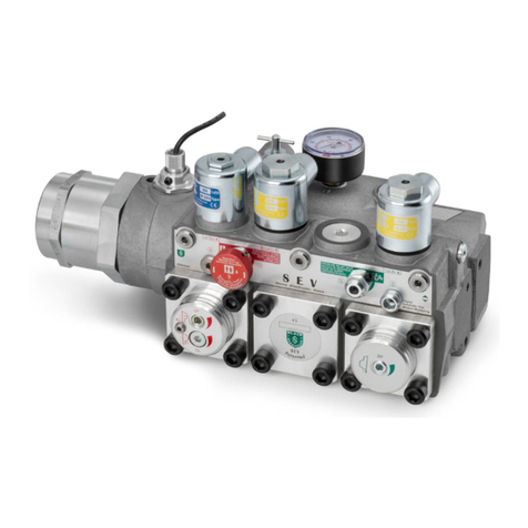
Blain Hydraulics
Blain Hydraulics SEV07 User manual
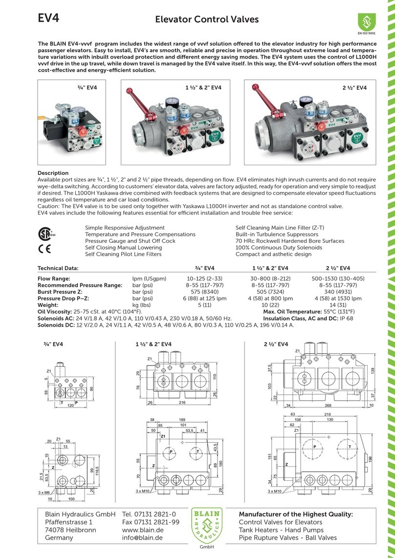
Blain Hydraulics
Blain Hydraulics EV4 User manual
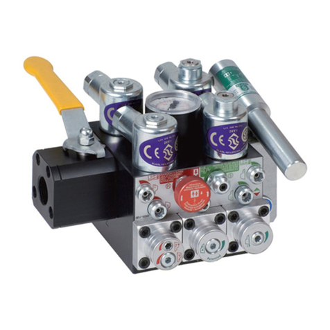
Blain Hydraulics
Blain Hydraulics EV100 Series User manual
Blain Hydraulics
Blain Hydraulics KV1P Guide
Blain Hydraulics
Blain Hydraulics SEV User manual
Blain Hydraulics
Blain Hydraulics EV100 Series User manual
Blain Hydraulics
Blain Hydraulics EV Series User manual

Blain Hydraulics
Blain Hydraulics SEV User manual

