706304/060515/ES-90 7
NOTE: Primary line voltage must not be greater or less than 8%
of rated voltage listed on voltage tap. For example, Tap 120 volt
(110 – 130 voltage range is acceptable) for excessively low line
voltage, a buck boost transformer maybe required. (Supplied by
others).
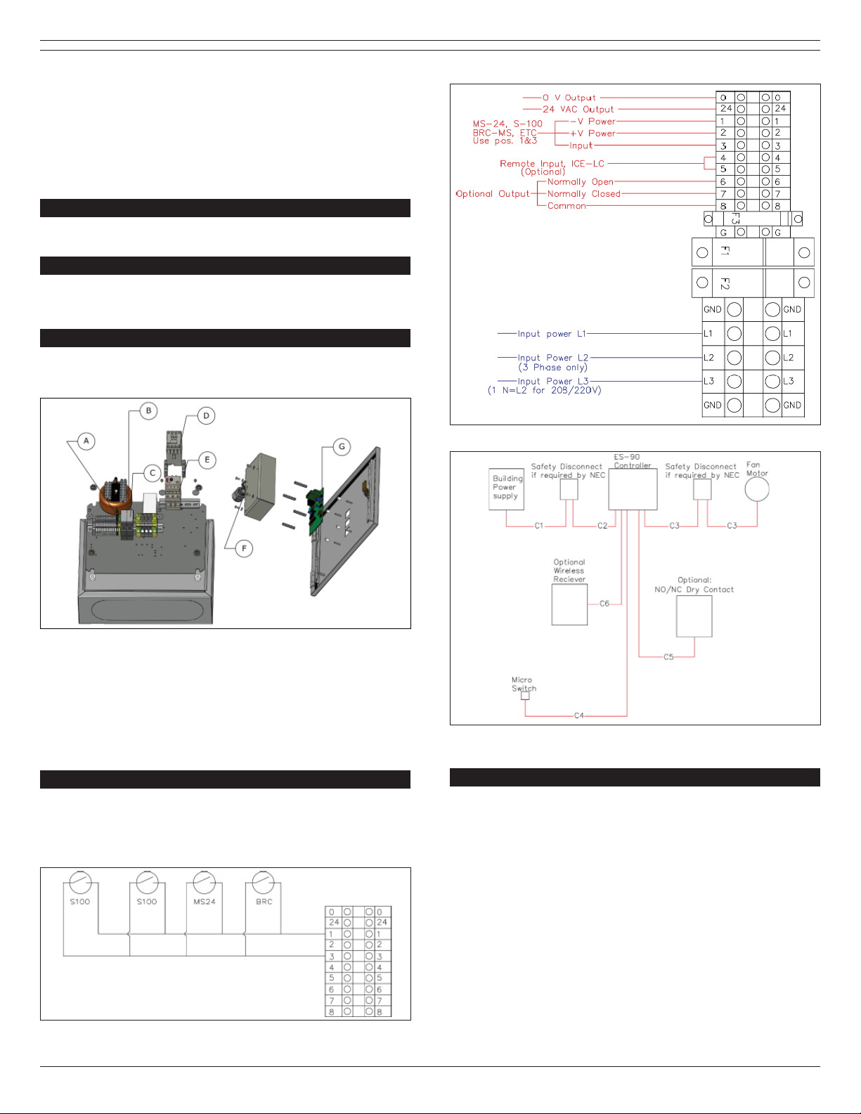
4.3.2 Primary Voltage Wiring
On the right side of the terminal block is the first terminal block
marked GND (green ground). Here you will connect your ground
wire (properly sized per NEC). In the second terminal block
marked L1, you will connect your first power wire. In the third
terminal block marked L2, you will connect your second power
wire. For the fourth terminal block (when applicable), marked
L3, you will connect your third power wire.
NOTE: The line supply voltage from your building, which will
supply your motor, shall be connected directly to L1, L2 for
single phase and L1, L2, and L3 for 3-phase. Re-check that rated
voltage corresponds with supply voltage to avoid damage to
electrical components or control wiring.
Table 2A on page 12 and Table 2B on page 13 show the fan
component sizing charts.
Please refer to local codes and requirements. These will take
precedence over the supplier wiring chart at the back of this
manual.
4.3.3 Field Power Wiring of Control Box, Safety
Disconnect and Fan Motor
The primary wiring of the electrical system must be rated for the
maximum amps and HP rating of the fan motor load as well as
the wiring voltage drop, which is calculated for the distance, you
are running. See Plymovent Wiring Chart in the back of this
manual as a guide for wiring. It is critical to always follow local
code requirements for selecting wire in instances where they
differ from Plymovent published recommendations.
NOTE: Field wiring, power supply panel and electrical safety
disconnect are provided by others. Plymovent assumes no
liability for any electrical installation and all national and local
codes and standards should be followed.
4.4 Primary Wiring Procedures (Control Wiring)
4.4.1 Control Voltage Wiring
The terminal blocks 0, 24V and 1 through 8 are used for low
voltage control wiring of optional wireless control system,
remote mounted activation devices for starting functions. An
optional remote alarm relay connection is available for
connection to Building Automation Systems (BAS).
MSR-24/2
Optional MSR-24/2 is a single throw double pole micro switch
that is installed on the exhaust hose reel. When the hose is
lowered the MSR-24/2 will activate the ES-90 and turn the fan
on. Auxiliary contact can be used to control an automatic
damper.
BRC-MS
Optional BRC-MS is a single throw double pole micro switch that
attaches to the BRC-450 spring balancer on fixed and boom
extractors. When the hose is pulled down to connect to the
vehicle, the BRC-MS will activate the ES-90 and turn the fan on.
Auxiliary contact can be used to control an automatic damper.
A maintained manual switch can also be placed in parallel in this
circuit for remote starting of the system.
NOTE: Control wires must be a minimum of 16 AWG/1.29 mm².
Smaller wire sizing will result in improper system operation.
4.4.2 Remote Alarm (optional)
Terminals 6, 7, and 8 are a relay dry contact connection for a
Building Automation System (BAS). Terminal block 8 provides
the common connection, terminal 7 provides a normally closed
contact connection and terminal 6 provides a normally open
contact connection.
NOTE: Relay output is a dry contact potential free and will
require additional control equipment depending on its use.
4.5 Transformer Wiring Procedure
4.5.1 Multi-tap Control Transformer
Designed by Plymovent to allow the field electrician the ability to
select the primary voltage of his/her choice. This voltage
selection ranges from 120 volt through 600 volt VAC. The
transformer has been designed to operate in both 50 and 60 Hz
environments.
NOTE: Primary line voltage must not be greater or less than 8%
of rated voltage listed on voltage tap. For example, Tap 120 volt
(110 – 130 voltage variant acceptable) for low line voltage, a
buck boost transformer maybe required (supplied by others).
4.5.2 Primary Voltage Connection
On the top right side of transformer you will find a terminal block
with 8 points of connection. Common black wire is connected to
the top terminal block (black to yellow wire) and will always
remain in this position regardless of the voltage adjustment that
you will be making. The voltage adjusting gray wire is preset for
the voltage ordered. You may be required to reposition the
voltage adjusting wire to the line supply voltage present at your
installation/facility. For example, adjusting to 120 volt line
voltage, move the voltage adjusting wire to wiretap second from
the top of terminal block (black to white). View yellow label for
correct wiretap color for each available voltage.
NOTE: Improper wiring will result in damage of other electrical
components. Re-check that rated voltage corresponds with
supply voltage to avoid damage to electrical components.
Always ensure power is off and all required procedures for
facility (such as lock out tag out) are properly followed before
making any adjustments to the control system.
WARNING!
Procedures which, if not carried out with the
necessary caution, may damage the product and/or
cause serious personal injury.
4.5.3 Secondary Voltage Connection
A 24VAC power supply is available using terminals labeled 0 and
24. This can be used to power an optional wireless control
system or automatic dampers.