Blanco FD906WX User manual

1
Instruction Manual for
Blanco 90cm
Freestanding Cooker
FD906WX

2
Dear Customer,
Thank you for buying a BLANCO Freestanding Cooker.
Before we continue telling you about this oven, we cordially invite you to become
part of the Blanco family by subscribing online. Please visit our website where
you can easily register for product/cooking demonstrations, and request Blanco’s
gourmet recipes. Go to www.blanco-australia.com and fill in the subscription
details in the contact us/showrooms section.
You will find that the clean lines and modern look of your Blanco Freestanding
Cooker blends in perfectly with your kitchen décor. It is easy to use and performs to
a high standard.
Blanco also makes a range of products that will enhance your kitchen such as
ovens, cooktops, rangehoods, dishwashers, microwaves, sinks and taps. There are
models to complement your new Blanco Freestanding Cooker.
Of course, we make every effort to ensure that our products meet all your
requirements, and our Customer Relations department is at your disposal, to answer
all your questions and to listen to all your suggestions.
Please complete the warranty card and keep your receipt as proof of purchase.
Retain all documents relating to the purchase of this product.
Blanco is committed to providing increasingly efficient products that are easy to use.

3
READ THE INSTRUCTIONBOOKLET BEFORE INSTALLING AND USING THE APPLIANCE.
It is important that you retain these instructions, proof of purchase as well as
other important documents about this product for future reference.
The manufacturer will not be responsible for any damage to property or to persons caused by
incorrect installation or improper use of the appliance.
Due to continual product development, Blanco reserves the right to alter specifications or
appearances without notice.
DO NOT OPERATE THIS APPLIANCE BEFORE READING THE
INSTRUCTION BOOK
DO NOT PLACE ARTICLES ON OR AGAINST THIS APPLIANCE
DO NOT STORE CHEMICALS OR FLAMMABLE MATERIALS OR
SPRAY AEROSOLS NEAR THIS APPLIANCE
DISPOSAL INFORMATION
•Most of the packing materials are recyclable. Please dispose of those materials
through your local recycling depot or by placing them in appropriate collection
containers.
•If you wish to discard this product, please contact your local authorities and ask for the
correct method of disposal.

4
CONTENTS
PRODUCT DESCRIPTION 5
INSTALLER TECHNICAL INFORMATION 6
Installing the cooker 6
Room ventilation 8
Appliance gas connection 9
Support legs 12
Anti-tilt system 13
Kick plate installation 15
Adaption to different types of gas 16
Appliance electric connection 18
Appliance Maintenance 20
Replacing parts 21
USE AND MAINTENANCE INFORMATION 22
Gas burner information 22
Control panel description 22
Using burners 23
Using the oven function knob 25
- Oven functions 25
- Using the pre – heating function 27
- Using the pizza function 27
- Using the traditional function 27
- Using the fan assisted function 29
- Using the fan forced function 30
- Using the grill function 31
- Using the fan grill function 31
Cooling fan operation 31
Using the minute minder 31
3 key electronic programmer 32
Other functions 34
Cleaning the appliance 35
- Catalytic self -cleaning liners – rear and sides 35
- Removing oven door 36
- Removing of inside glass 36
- Removing of roof tray 37
Troubleshooting 38

5
PRODUCT DESCRIPTION
The following is a brief overview of all features that are evident in this product.
- Square stainless steel design
- 6 burner configuration including Dual Control triple ring wok burner:
•1 x auxiliary burner(4.2 Mj/h ULPG / 4 Mj/h NG)
•3 x semi rapid burners(7.6 Mj/h ULPG / 6.7 Mj/h NG)
•1 x rapid burner (12.9 Mj/h ULPG /11.5 Mj/h NG)
•1 x dual wok burner(17.7 Mj/h ULPG / 17.5 Mj/h NG)
- Flame failure device fitted to each burner
- Dual Control Wok burner – the inner burner can work independently to the outer burner –
power details within manual
- Fully programmable touch control timer
- Single welded energy efficient cavity
- Triple glazed thermo-reflective door
- Removable inner glass and door
- Partially extendable telescopic runners x 2
- Catalytic self-cleaning liners – rear and sides
- 11 functions: Pre- heating, Top and bottom elements, Bottom element only, Top element only,
Full grill, Full grill with fan, Fan assisted, Fan forced, Bottom element with fan, Light, Defrost
- Full stainless steel kick plate
- 4 shelves/rack levels
- Removable oven roof
- Storage compartment
- Height adjustable feet
- Included accessories:
•2 x safety anti tip shelves
•1 x baking tray
•1 x grill insert
•Conversion kit
•Splashback
•
Stainless steel kick plate

6
INSTALLER TECHNICAL INFORMATION
Installation measurements
The product dimensions of this freestanding cooker are as follows:
895 W/L x 870- 940 H x 600 D mm
Please note that the stainless steel legs are adjustable from a height of 150 mm to 185 mm.
If the kick plate is placed on the freestanding cooker the product will require being at a height of 895
mm. This is the only way the kick plate will fit.
Please read this entire section to ensure that the cooker is installed safely and correctly and please
measure the actual product before cutting out for installation.
WARNING: TO BE INSTALLED BY AN AUTHORISED PERSON
WARNING: THIS APPLIANCE HAS BEEN DESIGNED FOR DOMESTIC USE ONLY
LOCAL AUTHORITY REQUIREMENTS
Check gas type and specifications plate placed on the bottom face of the unit. All gas fitting work,
service and repairs can only be performed by an authorized person and to local gas regulations.
Failure to comply with this condition will render the warranty invalid. Always unplug the appliance
before carrying out any maintenance operations or repairs. The walls of the units must not be higher
than work top and must be capable of resisting temperatures of 75’C above room temperature. Do
not install the appliance near flammable materials (e.g. curtains). The final act of any installation or
gas type conversion must be the full testing of this appliance, which includes leak testing, ignition of
each burner and the functionality of the burners separately and together.
WARNING: Keep all the dangerous packing parts (polystyrene foam, bags, cardboard, staples,
etc.) away from children.
WARNING: Young children should be supervised to ensure that they do not play with the
appliance.
INSTALLING THE APPLIANCE
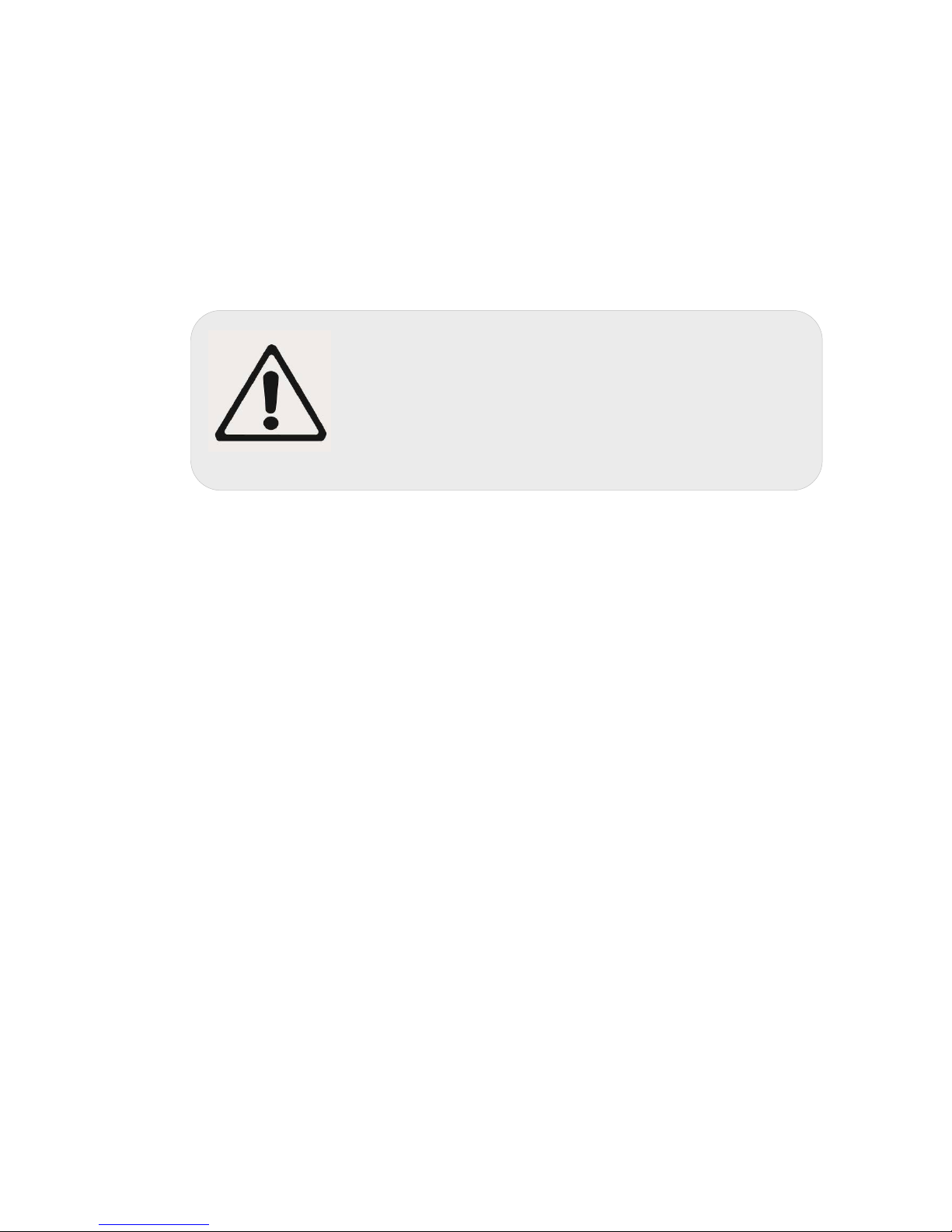
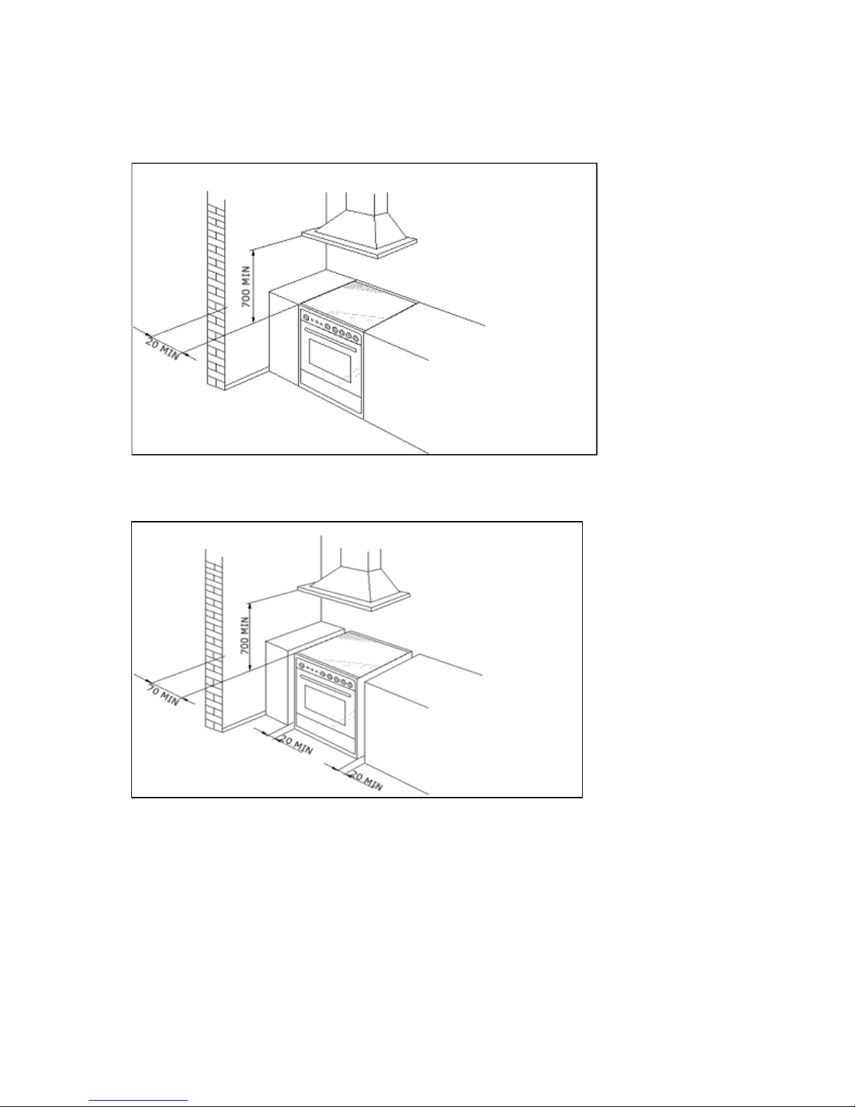
The appliance can be installed as a freestanding unit, next to a wall at a distance of no less than
20mm (Fig.2, Class 1 Installation) or inserted between two walls (Fig.1, Class 2 Subclass 1
Installation). A single sidewall that exceeds the height of the work surface is possible. This must be
at a minimum distance of 70 mm from the edge of the cooker (Fig.2, Class 1 Installation).
WARNING: Where this appliance is installed in a Marine craft or in Caravans, it shall NOT be
used as a space heater.
WARNING: In order to prevent accidental tipping of the appliance, for example by a child
climbing on to the oven door, the stabilizing means must be installed according to these
instructions.
WARNING: DO NOT MODIFY THIS APPLIANCE.
WARNING: The appliance is not intended for use by persons (including children) with reduced
physical, sensory or mental capabilities, or lack of experience and knowledge, unless they
have been given supervision or instruction concerning use of the appliance by a responsible
person for their safety.

7
Any walls of the adjacent furniture pieces and the wall behind the cooker must be made of heat-
resistant material that can withstand a minimum temperature of 75°C.
FIG. 1
FIG. 2

8
ROOM VENTILATION
To ensure that the appliance operates correctly, the room where it is installed must be continuously
ventilated. The room volume should not be less than 25m³ and the quantity of air needed should be
based on the regular combustion of gas and on the ventilation of the room. Natural air will flow
through permanent openings in the walls of the room to be ventilated. These openings will be
connected with the outside environment and should have a minimum cross-section defined by the
current national standards regarding room ventilation (Fig. 3).
These openings should be built so that they cannot be clogged.
Indirect ventilation is also permitted by taking air from the rooms adjacent to the one to be ventilated.
Fig.3
LOCATION AND AERATION
Gas cooking appliances must always evacuate the combustion products by means of hoods
connected to chimneys, flues or directly outside (Fig. 4). If a hood cannot be installed, it is possible
to use a fan installed on a window or directly facing outdoors, to be operated together with the
appliance (Fig. 5), provided that there is strict compliance with the ventilation regulations.
Fig. 4 Fig. 5

9
APPLIANCE GAS CONNECTION
IMPORTANT: This appliance must be installed by an authorized person.
WARNING: The appliance utilizes a threaded 1/2" gas cylindrical male fitting according to UNI-
ISO 228-1.
To connect the appliance to the gas network with a flexible rubber hose, a supplemental hose
nipple fitting is needed (Fig. 6)which is supplied with the appliance.
This flexible connection can be bought at a hardware store.
If using a fixed copper pipe connection
Gas connection
The cooker must be connected to the gas supply with upstream connection of an isolation valve in
accordance with the respective valid regulations. We recommend that the isolation valve be
fitted prior to the cooker to enable isolation of the cooker from the gas supply. The valve must be
easily accessible at all times.
To find out the factory set gas type, see label at rear of cooker.
The gas connection is via 1/2" compression. Connect the cooker to the gas supply and check for
gas soundness. NEVER use a naked flame to check for gas leaks.

10
Gas inlet (mm)- Nat gas Gas inlet (mm)- LPG
From RH rear side: 35 mm From RH rear side: 35mm
Up from floor: 590 mm Up from floor: 675 mm
Fig. 6
Gas inlet with different leg heights –
X quote in Fig 6 above from the floor in mm.
Min
NG: 560
LP: 645
Ref NG: 590 LP: 675
Max NG: 595 LP: 680
TABLE NO. 1
Energy consumption
FD906WX
Burners Gas type Pressure (kPa) Injector (mm) Mj/hr Watts
Small(
Auxiliary) Natural
U-LPG 1.0
2.75 0.92
0.56 4.00
4.2
30
00 W
Medium (semi
rapid)
Natural
U-LPG
1.0
2.75
1.17
0.73
6.7
7.6
Large( Rapid)
Natural
U-LPG 1.0
2.75 1.55
0.98 11.5
12.9
*
Wok Inner Natural
U-LPG 1.0
2.75 0.80
0.50 3.1
3.2
*
Wok Outer Natural
U-LPG 1.0
2.75 1.30
0.73 14.4
14.5

11
* The inner & outer wok operates from the same control knob. Please note that the inner wok can
operate on its own and the inner and outer wok can also operate together.

12
HEIGHT ADJUSTABLE LEGS
Legs are packed in the top box. Please read the above piece which also relates to the legs.
Legs should be installed with the appliance being near the location of final installation, they are not
secure for long transport. After unpacking the range, raise it about a foot to insert the legs in their
bases assembled on the lower part of the cooker and lower the range gently to keep any undue strain
from legs and mounting hardware. It is recommended to use a pallet or lift jack instead of tilting the
unit. Tilting the unit or dragging may easily break the legs.
If the legs are not used and the
cooker
i
s
mounted onto a
plinth
,
fit
t
ran
s
i
t
l
egs
to
all
ow
fo
r
c
learance
.
Once l
egs
are
adjusted
to a
nomina
l
cooker
he
i
gh
t
of 910
mm
,
fit the
ant
i-
tilt
r
estr
a
i
n
t
bracke
ts.

13
ANTI TILT SYSTEM
The appliance must be installed using the anti-tipping system provided.
1.
F
i
t
flat strap to rear of cooker at the
centerp
o
i
n
t
on l
ower
edge using
suppl
i
ed
screws.
2.
Mark
center
position of the cooker
i
ns
t
alle
d
pos
i
t
i
on
on
f
l
oor.
I
NTERSEC
TIO
N
OF
WAL
L
F'LO
O
R

14
3.
Measure from rear most
point
hob to mount
point
of
strap.
(
Dimens
i
on
A)
,
then
us
i
ng
D
i
men
s
i
on
A mark back edge of the bracket on cen
te
r
l
in
e
.
Use bracket to mark
fix
in
g
po
i
n
t.
BACKGUARD INSTALLATION INSTRUCTION
Remove the 2 screws that secure the work plan at the rear as shown in below drawing. Arrange the
backsplash and secure it to the bottom side with two screws removed. Further secure the Central up
stand with the screws supplied with the kit.

15
KICK PLATE INSTALLATION

16
ADAPTATION TO DIFFERENT TYPES OF GAS
WARNING: Please note that the images below may not be fully correct but are a good guideline
as to how the cooktop works.
WARNING: Before performing any maintenance operation, disconnect the appliance from
the gas supply and electricity network.
REPLACING THE NOZZLES TO OPERATE WITH ANOTHER TYPE OF GAS
BURNER ADJUSTMENT
Follow the instructions below to change the burner nozzles on the work surface:
1) Pull out the plug from the electric outlet to avoid any type of electric contact.
2) Remove the grids from the work surface (Fig. 7).
3) Remove the burners (Fig. 7).
Fig.7
4) Unscrew the nozzles using a 7 mm spanner, and replace them (Fig.8) with those needed
for the new type of gas according to what is indicated in Table 1
.
Fig. 8

17
Burner "MINIMUM" adjustment:
Work surface burner adjustment: follow the instructions below to adjust the work surface burner
minimum:
1) Light the burner and set the knob to the MINIMUM position (small flame).
2) Remove the knob of the valve that is press fit on the rod of that valve.
3) If the cooker is not equipped with safety valves on the surface burners, insert a small slotted
screwdriver into the hole on the valve rod (Fig. 9) and turn the choke screw to the right or left until
the burner flame is adjusted to minimum. If the cooker is equipped with safety valves, the choke
valve is not located in the rod hole but on the valve body (Fig. 10).
4) Ensure that the flame does not go out when switching quickly from the MAXIMUM to the
MINIMUM position.
Fig. 9 Fig. 10

18
APPLIANCE ELECTRICAL CONNECTION
The electric connection must comply with the current legal standards and regulations.
Before making the connection, check that:
•The system electrical rating and the current outlets are adequate for the
maximum power output of the appliance (see the label applied to the bottom of
the casing).
•The outlet or the system is equipped with an efficient ground connection in
accordance with the current legal standards and regulations. The manufacturer
will not be responsible for the non-compliance with these instructions.
Letter L (phase) = brown wire;
Letter N (neutral) = blue wire;
Ground symbol = green-yellow wire;
Fig. 11
•The power cord must be positioned so that a temperature of 75°C will not be reached at any
point.
•Do not use reductions, adapters or splitters since they might cause false contacts and
lead to dangerous overheating.
When the connection is made directly to the electric network:
•Use a device that ensures disconnection from the mains in which the contacts are
opened to a distance that permits complete disconnection according to the conditions for
over-voltage category III.
•Remember that the ground wire must not be interrupted by the circuit-breaker.
•As an alternative, the electric connection can also be protected by a high-sensitivity
residual current circuit- breaker but this may be subject to nuisance tripping due to
residual humidity in heating elements.
•It is highly recommended to attach the special green-yellow ground wire to an efficient
ground system.
WARNING: If the power cord is replaced, the ground wire (yellow-green) connected to the
terminal, should be longer than the other wires by about 2 cm.
WARNING: If the supply cord is damaged, it must be replaced by the
manufacturer
or
its service agent or a similarly qualified person in order to avoid
a hazard.

19
TABLE NO. 2: TYPES OF POWER CORDS
Work
surface
Oper
at-
ion
Ove
n
oper
a-
tion
Cross section
230V ~
230V 3~
400V 2N~
400V 3N~
Only gas burner
Gas oven / Gas grill
3 x 0.75mm²
-
-
-
Gas oven / Electric grill
3 x 1mm²
-
-
-
Electric Oven
3 x1mm² (MH)
3x1,5mm² (MX M9)
-
-
-
Ventilated Electric Oven
3 x 1,5mm²
-
-
-
Gas burner
+ 1 hot
plate
Gas oven / Gas grill
3 x 1mm²
-
-
-
Gas oven / Electric grill
3 x1,5mm² (MH)
3x2,5mm² (MX /M9)
-
-
-
Electric Oven
3x1,5mm² (MH)
3x2,5mm² (MX /M9)
-
-
-
Ventilated Electric Oven
3x2,5mm²
-
-
-
Gas burner + 2 hot
plate
Electric Oven
3x2,5mm²
4x1,5mm²
4x1,5mm²
5x1,5mm²
Ventilated Electric Oven
3x2,5mm²
4x1,5mm²
4x1,5mm²
5x1,5mm²
4 hot plate
Electric Oven
3x2,5mm²
4x1,5mm²
4x1,5mm²
5x1,5mm²
Ventilated Electric Oven
3x2,5mm²
4x1,5mm²
4x1,5mm²
5x1,5mm²
Ceran
Electric Oven
3x2,5mm²
4x1,5mm²
4x1,5mm²
5x1,5mm²
Ventilated Electric Oven
3x4mm²
4x1,5mm²
4x1,5mm²
5x1,5mm²
ATTENTION: The appliance conforms with the regulations AS4551 regarding gas
appliances for domestic use and AS/NZS 60335.2.6 regarding electrical safety and
CISPR14 regarding electromagnetic compatibility.
THREE-PHASE ELECTRIC CONNECTION
The cookers can also be connected to three-phase systems but normally are factory built for the
single-phase 230V connection, and are supplied with a power cord. Based on the connection system
used, install the power cord type indicated in table No.2.
To use the selected connection system change the jumpers on the terminal strip as indicated in the
diagram below. (Fig.12)
Fig. 12

20
APPLIANCE MAINTENANCE
ATTENTION: IMPORTANT WARNINGS
•For cookers resting on a base
ATTENTION: If the cooker rests on a base, take the measures necessary to prevent
the cooker from sliding along the support base.
•For cookers with electric ovens
ATTENTION: The unit becomes hot during use. Do not touch the heating elements
inside the oven.
•For cookers with electric ovens
ATTENTION: The accessible parts can become hot during use. Keep children away
from the appliance.
•For the food warmer compartment (or drop leaf in our case)
ATTENTION: The internal parts of the food warmer can become hot during use.
•For glass doors
ATTENTION: Do not use harsh abrasive cleaning products or metal spatulas with
sharp edges to clean the oven door’s glass since this could scratch the surface and the
glass could break.
WARNING: Do not use steam cleaners to clean the appliance.
WARNING: DO NOT MODIFY THIS APPLIANCE
Table of contents
Other Blanco Kitchen Appliance manuals
Popular Kitchen Appliance manuals by other brands

Brouwland
Brouwland VinoFerm 015.080.12 instruction manual

CONTINENTAL EDISON
CONTINENTAL EDISON PG-07 instruction manual

DCS
DCS DCS RD 484 GG PART LIST / SERVICE MANUAL

Scarlett
Scarlett SC-ET10D01 instruction manual

Henny Penny
Henny Penny ESC-115 Electric brochure

Silhouette
Silhouette DWC1534BLS owner's manual

Wine Corner
Wine Corner WINE C18IN user guide

Cook's Companion
Cook's Companion 2 Piece Ditanium manual

Zephyr
Zephyr UWB24C32BG Use, care and installation guide

Viking
Viking DFUR1541 Dimensions and specifications

Montgomery Ward
Montgomery Ward Chef Tested 767046 instruction manual

Panasonic
Panasonic SR-ZE185 operating instructions