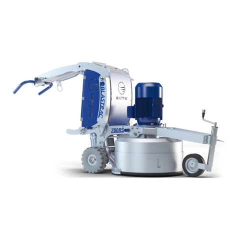
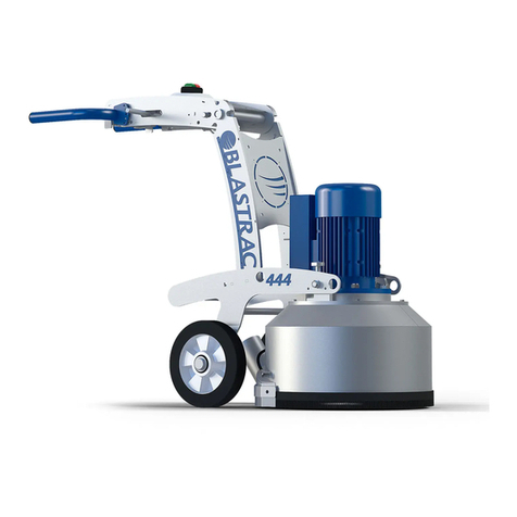
Blastrac BMG-2500 User manual

BMG-2500
MULTI FUNCTION GRINDING TOOL
January 2005
OPERATIONS AND MAINTENANCE MANUAL
KEEP THIS MANUAL WITH MACHINE AT ALL TIMES FOR USE BY OPERATORS AND
MAINTENANCE PERSONNEL!

Operating Instructions Manual
Table of Contents BMG-2500 MULTI GRINDER
2
JANUARY 2005 © International Surface Preparation Group, Inc.
Sections:
1.0 How to use this manual --------------------------------------------------------------------------------------------- 3
2.0 Specifications -----------------------------------------------------------------------------------------------------------3
3.0 Applications -------------------------------------------------------------------------------------------------------------4
4.0 General Safety Guidelines ------------------------------------------------------------------------------------------4
5.0 Pre-operation checklist -----------------------------------------------------------------------------------------------9
6.0 Operation -------------------------------------------------------------------------------------------------------------- 12
7.0 Parts diagram and lists---------------------------------------------------------------------------------------------- 15
8.0 Accessories list ------------------------------------------------------------------------------------------------------- 25
9.0 Performance charts ------------------------------------------------------------------------------------------------- 25
10.0 Maintenance and inspection -------------------------------------------------------------------------------------- 26
11.0 Operating tips --------------------------------------------------------------------------------------------------------- 32
12.0 Warranty and service ----------------------------------------------------------------------------------------------- 34
List of Figures:
Figure 1 - Warning label - read and understand manual -------------------------------------------------------------6
Figure 2 - Warning label - read and understand manual ------------------------------------------------------------ 9
Figure 3 – Machine components /3A control panel --------------------------------------------------------------------9
Figure 4 – Warning label –rotating cutter head and tool holder layout ----------------------------------------- 10
Figure 5 – Handle adjustment components --------------------------------------------------------------------------- 11
Figure 6 – Warning – flying debris and loud noise, wear eye and ear protection ---------------------------- 12
Figure 7 – Connection to dust collector -------------------------------------------------------------------------------- 13
Figure 8 – Movement of machine ---------------------------------------------------------------------------------------- 14
Figure 9 – Parts diagram -------------------------------------------------------------------------------------------------- 15
Figure 10 – Electrical diagrams------------------------------------------------------------------------------------------- 23
Figure 11 – Lubrication ----------------------------------------------------------------------------------------------------- 26
Figure 12 – Warning label – Hot surface ------------------------------------------------------------------------------- 27
Figure 13 – Warning label – Hot surface inside ---------------------------------------------------------------------- 27
Figure 14 – Tapered plug holder ----------------------------------------------------------------------------------------- 28
Figure 15 – Holder blocks attached to block holder arm ----------------------------------------------------------- 29
Figure 16 – Square tungsten carbide cutters mounted on holder block ---------------------------------------- 29
Figure 17 – Proper installation and rotation of carbides ------------------------------------------------------------ 30
Figure 18 – Clean-out area for vacuum port -------------------------------------------------------------------------- 31
List of Tables:
Table 1 – Branch circuit and extension cord requirements ----------------------------------------------------------7
Table 2 – Tool speed chart ------------------------------------------------------------------------------------------------ 12
Table 3 – Parts list ----------------------------------------------------------------------------------------------------------- 15
Table 4 – Performance chart – Model BMG-2500 ------------------------------------------------------------------- 25
For answers to your questions about this product, contact your local
? Distribution Representative or call: Blastrac
1-800-256-3440 or 1-405-478-3440
7 am – 6 pm, Mon-Fri (CST)
Blastrac •6215 Aluma Valley Dr. •Oklahoma City, OK 73121 USA

Operating Instructions Manual BMG-2500 MULTI GRINDER
3
JANUARY 2005 © International Surface Preparation Group, Inc.
1.0 How to use this manual
Read through this entire operations and maintenance manual before using your new machine. Pay close
attention to the General Safety Guidelines, Dangers, Warnings and Cautions.
Figure 1 – Warning label – read and understand manual
2.0 Specifications
BMG-2500
Motor: 5 HP, single phase
Power Source: 230 VAC, single phase, 60 Hz
Current: 23 amps
Motor RPM: 1750 rpm
Power Cord Length: 25 feet
Vacuum hose port: 2 inch diameter
Weight: 570 pounds with weights
Tool RPM: 400 rpm max.
Pressure on Tools: Rear wheels = 370 LBS / Front wheels = 200 LBS
Pocket weights may be distributed on machine to vary the working
pressure on floor (4 X47.5 lbs each)
Tools Available: Various diamond and optional slicer kit using tungsten carbide cutters
(contact your local Blastrac sales office for more information)
Dimensions: 48”L x 25”W x 40”H (auxiliary handle in stowed position)
Cleaning path: 22 in width
Recommended vacuum: Blastrac Model 1-13DC or Model 4-54DC single phase

Operating Instructions Manual BMG-2500 MULTI GRINDER
4
JANUARY 2005 © International Surface Preparation Group, Inc.
3.0 Applications
Typical applications include removing thick, horizontal elastomeric floor coatings and adhesives such as
tile mastics or carpet glue. The BMG-2500 uses two counter-rotating heads that hold either tungsten
carbide cutters or diamond plugs. The tungsten carbide cutters are used to slice coatings and adhesives
apart and the diamond plugs can be used to clean off any remaining material or to remove hard, brittle
coatings and paints or prepare concrete surfaces for coating. The water tank is used to introduce water
into the pathway of the cutters or plugs, helping eliminate buildup of materials on the cutters or plugs.
Water introduced on the floor in certain applications will help cool the diamond plugs and reduce dust. If
water is not needed, clean-up time will be reduced and a cleaner surface will be achieved. In dry
grinding/slicing applications, this machine is designed to be used with a Blastrac Model 1-13DC or 4-54
dust collection system and appropriate respiratory protection.
4.0 General Safety Guidlines
The purpose of safety symbols and explanations is to attract your attention to possible hazards and
explain how to avoid them. The safety symbols and explanations do not by themselves eliminate any
danger. The instructions or warnings they give are not substitutes for proper accident prevention
measures.
DANGER: Indicates an imminently hazardous situation that if not avoided, will result in death or serious
injury. This warning is limited to the most extreme situations.
WARNING: Indicates a potentially hazardous situation that, if not avoided, could result in death or
serious injury.
CAUTION: Indicates a potentially hazardous situation that, if not avoided, may result in minor or
moderate injury. It may also be used to alert you to potentially unsafe practices.
4.1 DO KNOW YOUR MACHINE. Read and understand the operations and maintenance manual.
Read any additional manuals attached from other manufacturers. Learn the applications and
limitations as well as the specific potential hazards related to this machine.
4.2 DO DRESS PROPERLY. Do not wear loose clothing or jewelry that can be caught in moving
parts. Wear protective hair covering to contain long hair. The use of appropriate gloves and non-
skid footwear are recommended when working with this machine.
4.3 DO PROTECT YOUR FEET. Observe all applicable local, state and federal safety regulations.
Wear OSHA approved foot protection when operating this machine.

Operating Instructions Manual BMG-2500 MULTI GRINDER
5
JANUARY 2005 © International Surface Preparation Group, Inc.
4.4 DO PROTECT YOUR EYES. Observe all applicable local, state and federal safety regulations.
Wear OSHA-approved safety glasses when operating this machine.
4.5 DO NOT OPERATE OR MAINTAIN WITHOUT PROPER RESPIRATORY PROTECTION.
Follow OSHA approved respiratory protection standards when operating this machine in a dry
operation with a dust collector to avoid possible airborne contaminants. Grinding and cutting
concrete produces dust that may generate airborne respirable crystalline silica which if can lead
to silicosis and death. Observe all applicable local, state and Federal safety regulations that
pertain to the equipment, the products being operated and the substances being removed from
the surface.
4.6 DO NOTDO NOT USE IN DRY OPERATION WITHOUT AN APPROVED DUST COLLECTOR
SYSTEM. This machine is designed and ntended for use with an approved dust collection
system as recommended on page 3 in this manual. The dust collector system is intended to
reduce or eliminate the escape of potentially hazardous or nuisance dust into the environment.
4.7 DO PROTECT YOUR HEARING. Observe all applicable local, state and federal safety
regulations. Wear OSHA-approved hearing protection when operating this machine.
4.8 DO AVOID A DANGEROUS ENVIRONMENT. Before starting the machine, survey the work area
for hidden obstructions and/or uneven cracks or joints. Do not expose machine to rain. Do not
use machine in standing water conditions. Keep work area well lit. Do not allow machine to cross
over the edge of the concrete slab or work surface.
4.9 DO KEEP WORK AREA CLEAN. Cluttered work areas and debris buildup on floors creates an
unsafe work environment.
4.10 DO AVOID FLAMMABLE LIQUIDS OR GASES. Power tools produce sparks during operation
and when starting or stopping electric motors. Never use machinery in dangerous sites containing
materials that are combustible or explosive.
4.11 DO GUARD AGAINST ELECTRIC SHOCK. Before starting machine, insure that an assured
ground circuit is made with the green ground wire in the power cord connected to the ground
circuit at the power source.
4.12 DO KEEP CHILDREN AND VISITORS AWAY. Do not let children or visitors contact machine or
extension cord. Keep children and visitors away from the work area at all times.
4.13 DO STORE IDLE MACHINE. When not in use, machine should be stored in a dry and secure
location. Keep machine out of the reach of children or unqualified operators.
4.14 DO NOT FORCE MACHINE. The machine will do a better and safer job when operated at the
rate for which it was designed.
4.15 DO USE CORRECT MACHINE. Do not force the machine or attachments to do the job of a larger
machine. Do not use the machine for a purpose not intended.
4.16 DO OBTAIN MATERIAL SAFETY DATA SHEET (MSDS) FOR ALL MATERIALS. Refer to the
MSDS of all substances in and around the machine and follow the appropriate safety guidelines
associated with the use/exposure of the substance.
4.17 DO NOT ABUSE POWER CORD. Never pull machine by power cord, run over cord with
machine or forklift, or pull on cord by extending machine distance from power source too far.

Operating Instructions Manual BMG-2500 MULTI GRINDER
6
JANUARY 2005 © International Surface Preparation Group, Inc.
Connect power cord to power source and power cable extensions with approved plugs and with
machine power switch turned off. If cord is damaged, disconnect power and repair immediately.
4.18 DO NOT OVEREACH. Keep proper footing and balance at all times.
4.19 DO MAINTAIN MACHINE WITH CARE. Keep machine clean and use sharp cutters or diamond
plugs that are in good condition. Keep handles dry, clean and free from oil and grease. Follow
instructions for lubricating and changing accessories or tools.
4.20 DO DISCONNECT MACHINE FROM POWER SOURCE. When not in use, before servicing and
when changing cutters or plugs, always disconnect power cord from power source.
4.21 DO AVOID UNINTENTIONAL STARTING. Do not carry or transport machine with finger or hand
on the power switch while power cord is connected to power source.
4.22 DO NOT LEAVE MACHINE RUNNING UNATTENDED. TURN POWER OFF. Always have full
control of the machine until all machine components have come to a complete stop.
4.23 DO REMOVE ADJUSTING WRENCHES AND TOOLS. Check to see that wrenches and tools, or
any other loose objects are removed from machine before turning it on.
4.24 DO STAY ALERT. Watch what you are doing. Use common sense. Do not operate machine
when you are not fully alert.
4.25 DO NOT USE DRUGS, ALCOHOL, MEDICATION. Do not operate machine while under the
influence of drugs, alcohol, or any medication.
4.26 DO CHECK FOR DAMAGED PARTS. Before any use of the machine, check for damaged parts
that should be replaced. Check for alignment of moving parts, binding of moving parts, breakage
of parts, mounting of cutter or diamond tools and any other condition that may affect machine
operation. A guard, power switch or other part that is missing or damaged should be properly
repaired or replaced by an authorized service center. Do not operate machine if power switch
does not turn machine on and off.
4.27 DO CHECK VOLTAGE. Before connecting machine to a power source, be sure the voltage
supplied is the same as that specified on the nameplate of the machine or motor. A power source
with voltage greater than that specified for the machine can result in serious injury to the user and
damage to the machine. If in doubt, do not plug in machine. Using a power source with voltage
less than the nameplate rating is also harmful to the motor.
4.28 DO UNDERSTAND ELECTRICAL REQUIREMENTS FOR USING EXTENSION CORDS.
Length of extension cord should be limited to electric supply limitations and should never
exceed 100ft in length. Use only (3) three conductor cords on the single-phase machines. Make
sure that any extension cord used is in good condition. Disconnect power source and replace or
repair damaged cords and plugs before starting the machine. When using an extension cord, be
sure to use one heavy enough to carry the current the machine will draw. An undersized cord will
cause a drop in line voltage, resulting in loss of power and overheating. Table 1 shows the correct
size and type of conductor to use, depending on cord length and nameplate ampere rating. If in
doubt, use the next heavier gauge. As the gauge number decreases, the cord thickness
increases.


Operating Instructions Manual BMG-2500 MULTI GRINDER
7
JANUARY 2005 © International Surface Preparation Group, Inc.
Branch Circuit Requirements
Machine Total Amperage
Draw Customer Provided
Circuit Protection Cord Provided
With Machine Extension Cord
Requirements
BMG-2500 (5 HP) 23 30 Amp 50FT 8/3 Type W
Blastrac 4-54 DC 14.2 55FT 8/3 Type W
Both Units Together 35.2 50 Amp 8/3 Type W
*Machine is supplied with 50 ft of power cord with no electric plugs. Be sure to use electrical
connections that meet the amperage and voltage requirements of the machine and follows the
guidelines referred to in 4.28
Table 1 – Minimum gauge for extension cords
4.28 DO USE EXTENSION CORDS FITTED WITH PROPER PLUGS. When machine is used with
any extension cord, be sure to use plugs and receptacles rated for proper voltage and amperage
as prescribed by the National Electric Code. Make sure that all extension cords are wired the
same, matching wire colors and that the ground wire (green) is secured in its proper position.
4.29 KEEP ALL GUARDS AND COVERS IN PLACE. Do not remove guards or covers that have been
factory mounted. They perform important safety roles. Keep them in the proper positions.
4.30 SECURELY MOUNT ACCESSORIES AND TOOLS TO THEIR HOLDERS. Extra care must be
taken to ensure that tools are correctly mounted on the correct holders and that tool holders and
mounting brackets are secured in their proper position. Damage to the tools, holders and floor
surface and/or injury can occur if not properly tightened and secured.
4.31 ALWAYS KEEP THE MOTOR COOLING FAN GUARD UNCOVERED. Do not block vent
openings of guard over motor cooling fan. Vent openings are necessary for adequate motor
cooling. Do not operate motor with fan guard removed.
4.32 NEVER TOUCH THE MOVING PARTS. Never touch moving parts such as tool holders, cutters,
diamond plugs, or motor cooling fan, etc.
4.33 STOP OPERATION IMMEDIATELY IF ANY ABNORMALITY IS DETECTED. Stop using
machine immediately if any abnormalities are observed during operation. Some examples of
abnormalities include unusual noise and vibration.
4.34 DO NOT CLEAN PLASTIC PARTS OR MACHINE WITH SOLVENT. Solvents such as gasoline,
thinner, benzene, carbon tetrachloride and alcohol may damage and crack plastic parts, handle
grips, electric cords, as well as damage painted surfaces of the machine. Do not clean them with
such solvents. Clean plastic parts, electric cords and handle grips with a soft cloth lightly
dampened with soapy water. Refer to the MSDS of all substances in and around the machine and
follow the appropriate safety guidelines associated with the use/exposure of the substance.
4.35 WHEN REPLACING A COMPONENT PART, USE THE SAME TYPE. When replacing a
component part with a new one, use only parts with equal or better operating specifications.
Never attempt to repair machine unless you are completely familiar with proper procedures and
techniques required.

Operating Instructions Manual BMG-2500 MULTI GRINDER
8
JANUARY 2005 © International Surface Preparation Group, Inc.
4.36 DO NOT MODIFY MACHINE. Do not modify machine from its original design without written
permission of the manufacturer. Non-authorized modifications can lead to serious injury or death.
4.37 SAVE THESE INSTRUCTIONS. Refer to this operations and maintenance manual frequently and
use it to instruct others who may operate the machine.
4.38 MAKE SURE OPERATOR CONTROLS ARE WORKING CORRECTLY. Do not operate the
machine if the operator controls are not working correctly. Test the stop, start and emergency
stop controls each time you start the machine. If your machine is equipped with a variable speed
drive, make sure the speed is set at its lowest speed setting before starting the machine.

Operating Instructions Manual BMG-2500 MULTI GRINDER
9
JANUARY 2005 © International Surface Preparation Group, Inc.
5.0 Pre-operation checklist
Figure 2 – Warning label – read and understand manual
5.1 Read entire operations and maintenance manual. Be familiar with machine and its parts. See
figures 1 through 16.
Figure 3 – Machine components
A – Adjustable operator’s
handle
B – Machine leveling
adjustment knob
C – Water tank fill cap
D – Pocket weights
E – Dust guard and brush
Figure 3A – Control Panel
A – On/ Off control knob
B – Emergency kill switch
C- Emergency Lanyard

Operating Instructions Manual BMG-2500 MULTI GRINDER
10
JANUARY 2005 © International Surface Preparation Group, Inc.
5.2 Contact with foreign objects could cause machine to rotate violently. Before operating the
machine on any surface it is strongly recommended that you walk the floor, looking for
obstructions on the surface. These obstructions could include metal studs, anchor bolts, conduit
stubs, electrical outlet boxes, nails, holes and uneven floors caused by cracking and settling.
Serious injury to the operator and to the machine could occur if not avoided. Mark these areas
clearly so it will be easy for the operator to avoid while running the machine.
5.3 Observe condition of work environment. Make sure the work environment meets all working
conditions discussed in section 4.0, General Safety Guidelines.
5.4 Obtain MATERIAL SAFETY DATA SHEET (MSDS) for all work surface materials. Refer to
the MSDS of all substances in and around the machine and follow the appropriate safety
guidelines associated with the use/exposure of the substance. Do not attempt to operate this
machine without MSDS information.
5.5 Make sure that the tools are seated and fastened securely in their proper tool holders.
Follow instructions in sections 10.6 and 10.7 for installation and inspection of both diamond plugs
and tungsten carbide cutters. Tungsten carbide cutters must be used only with the tungsten
carbide holders and diamond plugs must be used only with the diamond plug holders. The
tungsten carbide holders that are provided with your machine consist of one (1) left hand holder
and one (1) right hand holder to facilitate the counter-rotating operation of the machine. See
figure 4. The diamond plug holders are not direction sensitive.
Figure 4 – Warning label – rotating cutter head
5.6 Check to make sure that the electrical connection is correct and secured by a properly
rated plug on the machine’s electrical cable, which is then plugged into the power source.
Maintain an assured ground circuit on all electrical connections, utilizing the machine’s
green wire in the electrical cable and the grounding circuit at the power source. Follow all
applicable codes, such as the National Electric Code.

Operating Instructions Manual BMG-2500 MULTI GRINDER
11
JANUARY 2005 © International Surface Preparation Group, Inc.
5.7 Inspect the machine’s electrical cable and plugs daily for cuts or nicks in the outer shield
or damage to the plug. Disconnect power source and replace or repair damaged cords and
plugs. When using any electrical extension cord, check to make sure that it is rated for the proper
voltage and amperage capacity. Use extension cord of sufficient gauge thickness. See section
4.27 and table 1.
5.8 Check to see that the machine power switch is in the off position, turned completely in the
left hand direction, before plugging cord into the power source and the kill switch is in the
off (down) position . Make sure the power plug and receptacle are of the same manufacturer
and that they fit securely. Do not operate machine if the receptacle connection is loose.
5.9 Check for missing or loose bolts, nuts and screws. Tighten loose bolts, nuts and screws and
replace those missing. Check for loose or missing parts and tighten or replace them.
5.10 Adjust the machine to a level operating position. These settings vary based on the tooling
being utilized on the grinding heads as well as the weight transfer position that is determined on
the use of the front or rear set of wheels. With the machine in the off position. Raise adjustment
knob from recess and crank handle to lower the front or rear set of wheels. The machines wheels
are installed on a cantilever system. Turning the adjustment handle will result in either set of
wheels moving up or down. The operator must turn the handle several turns to determine the
direction of the wheel set required. The wheels furthest to the rear of the machine (operator
position) is designed for heavy grinding applications. The small set of wheels located toward the
front of the machine is designed to lighten the overall weight applied to the grinding heads. The
light position is ideal for light grinding, polishing, and some slicing applications. Once wheels
touch the ground use reference level located on the right side handle upright to find a level
position. If machine is operated in a “non-level position” uneven wear and unneeded stress will
occur on moving parts. In some extreme cases of improper adjustment the machine will be
difficult to control over work surface. See figure 5.
Figure 5 – Handle adjustment components

Operating Instructions Manual BMG-2500 MULTI GRINDER
12
JANUARY 2005 © International Surface Preparation Group, Inc.
5.11 Make sure that the machine and grinding equipment are fully in the down position and are
contacting the floor before starting the motor. Adjust dust guard so that it touches the floor.
See section 10.2. In dry grinding/slicing applications, connect machine to an approved dust
collection system. See recommendation for dust collector/ vacuum on page 3 of this
manual.
5.12 Secure the machine from moving when starting the motor by gripping handle bar firmly
with one hand with safety lanyard attached (recommend left hand). The free hand can
than be used to engage the start control.
5.13 Dress properly. Wear eye, ear, foot and respiratory protection. See section 4, General
Safety Guidelines and see figure 6.
5.14
Figure 6 – Warning – flying debris and loud noise,
wear eye and ear protection
6.0 Operation
6.1 The Blastrac BMG-2500 has the capability to run two types of tools; either diamond /polishing
plugs or tungsten carbide cutters.
Tool Motor rpm Tool rpm
Diamond plugs 0 – 1450 400 rpm maximum
Tungsten carbide cutters 0 - 1450 400 rpm maximum
Table 2 – Tool speed chart
The machine can be converted to work with either diamond plugs or tungsten carbide cutter
tools by switching the tool holders. Follow the directions for switching tool holders and
installing the tools as shown in section 10.0, Maintenance and Inspection.
6. 2 Make sure that you have followed all instructions in sections 4.0 and 5.0 on connecting the
machine to power and inspecting the floor area you will be working on for hidden dangers. In dry
grinding/slicing applications, make sure that the machine is connected to an appropriate
dust collector system and that the dust collector operation and connection instructions
are followed. See figure 7. Before dry grinding/slicing, turn on the dust collector before operating
the Blastrac BMG-2500 and ensure respiratory protection is being worn.

Operating Instructions Manual BMG-2500 MULTI GRINDER
13
JANUARY 2005 © International Surface Preparation Group, Inc.
Figure 7 – Connection to dust collector
6. 3 Make sure the machine is fully contacting the floor and none of the tools are dislodged from their
holders. In dry grinding/slicing applications, turn the dust collector on and make sure all hose
connections are secure. Hold on to the handle of the machine with one hand and with the other
hand, turn the motor start button. Start and stop the machine once to check that all of the tools
are secure in their holders and the operator controls are working correctly. Make sure the
emergency stop button is operating correctly each time the machine is started. If a tool becomes
dislodged, you will hear a clunk noise and you must immediately stop the motor and re-attach the
tool. A smooth sound will result from of the tools in their holders. Grasp the handle of the
machine with both hands and steady your stance to control the movement of the machine.
6.4 The proper method of operating the machine is to swing the machine from side to side in a
sweeping motion, while pushing the machine in a forward direction. With this movement, the most
productive pattern can be created allowing for greater production capacity and even coverage of
the work area. See figure 8. If the machine is left running on one area of the floor too long, it will
create a depression in the surface. This result is usually not desired and may require corrective
repairs to those areas. The Blastrac BMG-2500 has a unique floating head coupling system that
follows the contours of the floor and attacks the high spots first. It is important to recognize that
in order for the machine to remove materials from the low spots on the floor, it must
reduce the surrounding higher areas first. The sweeping side-to-side motion of the machine
will help even out the floor. If the floor has severe differences in elevations from high to low areas,
the choice must be made to either remove the entire floor down to the low spots or to fill the low
areas by other methods or techniques.

Operating Instructions Manual BMG-2500 MULTI GRINDER
14
JANUARY 2005 © International Surface Preparation Group, Inc.
Direction of Travel
Figure 8 – Movement of machine
(Looking down through the Top of the machine)

Operating Instructions Manual BMG-2500 MULTI GRINDER
15
JANUARY 2005 © International Surface Preparation Group, Inc.
7.0 Parts diagram for Blastrac® BMG-2500
Figure 9.1 – BMG-2500 parts diagram

Operating Instructions Manual BMG-2500 MULTI GRINDER
16
JANUARY 2005 © International Surface Preparation Group, Inc.
ITEM # PART # DESCRIPTION QTY.
1 77309
HANDLE BAR 1
2 10029
SCREW, CAP 3/8-24 X 1-3/4 4
3 10025
WASHER, FLAT 3/8 8
4 10004
NUT, LOCK 3/8-24 4
5 61108
GRIP, HAND 1" MODEL SX 2
6 77325
HANDLE EXTENSION 1
7 10030
SCREW, CAP 3/8-24 X 2 2
8 10025
WASHER, FLAT 3/8 8
9 10811
WASHER, LOCK 3/8 2
10 10014
NUT 3/8-24 2
11 14023
KNOB, BALL 1-3/8 W/ 1/2-13THD, BLK. 1
12 50550
SLEEVE FOR 1/2" CAPSCREW,
TAPERED 1
13 10346
SCREW, SKT. HD. 1/2-13 X 4-1/2 ZINC 1
14 61106
DECAL, CUT CONTROL - DN/UP (LARGE) 1
15 75004
HANDWHEEL, LARGE W/ 5/8-8 X 16"ROD 1
16 75012
SPACER, HANDWHEEL 5/8"ID X 3/8"L 1
17 80009
BEARING, BALL 5/8" 2-HOLE FLANGE 1
18 55010
SPACER, HANDWHEEL 5/8"ID X 3/4"L 1
19 50008
NUT 5/8-8 ACME 1
20 10412
BOLT, CARRIAGE 1/4-20 X 1 FULL THD. 2
21 10602
WASHER, FLAT 1/4 2
22 10861
NUT, KEPS 1/4-20 2
23 77310
LINKAGE, UPPER SUPPORT 1
24 75006
LINKAGE, CUT CONTROL LOWER 1
25 10343
SCREW, CAP 1/2-20 X 2-1/2 1
26 10312
WASHER, FLAT 1/2 2
27 10045
WASHER, LOCK 1/2 1
28 10072
NUT 1/2-20 1
29 10407
NUT, LOCK 1/2-13 2
30 10312
WASHER, FLAT 1/2 2
31 77329
SPRING, COMP.734"OD X 1.31"FL 4
32 77328
SPRING, COMP. 1.468"OD X 2.5"FL 2
33 77326
CARRIAGE, WHEEL 1
34 77327
AXLE SHAFT 1
35 68008
WHEEL 8 X 1-5/8 X 3/4"BRG., POLY 2
36 10009
WASHER, FLAT 3/4 4
37 10306
PIN, COTTER 3/16 X 1-1/4 2
38 10932
WHEEL 4 X 1-1/2 X 3/8"BRG., POLY 2
39 10393
SCREW, CAP 3/8-24 X 2-1/2 2
40 10025
WASHER, FLAT 3/8 8
41 10004
NUT, LOCK 3/8-24 2

Operating Instructions Manual BMG-2500 MULTI GRINDER
17
JANUARY 2005 © International Surface Preparation Group, Inc.
42 77308
BOLT, ALLTHREAD ROD 5/8-11 X 18 1
43 10073
WASHER, FLAT 5/8 2
44 10809
NUT, LOCK 5/8-11 1
45 77311
MAIN FRAME & GEAR CASE 1
46 77330
SKIRT 1
47 10806
SCREW, CAP 5/16-18 X 1 5
48 10801
WASHER, LOCK 5/16 5
49 10213
WASHER, FLAT 5/16 5
50 10113
SPACER, STEEL 9/16OD X 3/8ID X 7/32 2
51 77331
PANEL, VACUUM PORT 1
52 77007
COVER, GEAR CASE 1
53 10018
SCREW, CAP 1/4-20 X 3/4 10
54 10038
WASHER, LOCK 1/4 10
55 10602
WASHER, FLAT 1/4 10
56 10005
PLUG, HOLE 7/8" (CHROME) 1
57 77008
BEARING, BALL 1" 4-HOLE FLANGE, ND 4
58 10450
WASHER, LOCK 7/16 16
59 10481
NUT 7/16-20 16
60 77009
BEARING, BALL 3/4" 4-HOLE FLANGE 2
61 10309
SCREW, CAP 3/8-24 X 1-1/4 PLATED 4
62 10811
WASHER, LOCK 3/8 4
63 10014
NUT 3/8-24 4
64 77011
SHAFT, PINION GEAR 3/4DIA X 7-3/8"L 1
65 77053
GEAR, SPUR 25 TOOTH (PINION) 1
66 10037
PIN, ROLL 1/4 X 1-1/2 1
67 77012
GEAR, SPUR 112 TOOTH (DRIVEN) 2
68 10007
PIN, ROLL 3/8 X 2-1/2 2
69 77013
SHAFT, LARGE GEAR 1"DIA X 7-13/16"L 2
70 10009
WASHER, FLAT 3/4 1
71 10063
PIN, ROLL 3/8 X 2 2
72 77345A
DISC ASSEMBLY (SEE 9.4 FOR DETAIL) 2
73 77342
LEVEL, TUBULAR 1
74 10877
SCREW, CAP STSHW 10-24 X 1/2 2
Figure 9.1 – BMG-2500 parts list

Operating Instructions Manual BMG-2500 MULTI GRINDER
18
JANUARY 2005 © International Surface Preparation Group, Inc.
Figure 9.2 – BMG-2500 parts diagram

Operating Instructions Manual BMG-2500 MULTI GRINDER
19
JANUARY 2005 © International Surface Preparation Group, Inc.
ITEM # PART # DESCRIPTION QTY.
1 77301
TANK, WATER, 10 GAL. CAPACITY 1
2 61056
CAP, TANK 4
3 77302
WEIGHT, 50 LB. 1
4 77313
PAD, WEIGHT BLOCK 2
5 77312
LEVER, WATER VALVE 1
6 77303
ROD, WATER VALVE LEVER 1
7 10125
PIN, DETENT RING 1/2 X 1-1/2 E.L. 2
8 10728
PIPE NIPPLE, CLOSE 1/2NPT (BLACK) 1
9 77304
VALVE, GAS BALL 1/2 FPT 1
10 10679
NIPPLE, HEX 1/2NPT (BRASS) 1
11 10726
BUSHING, HEX 3/4 X 1/2 NPT (BRASS) 1
12 11570
INSERT, SWVL.FEM. 1/4HOSE X 3/4GHT 1
13 10762
CLAMP, HOSE SPRING-TYPE 3/8"
GREEN 2
14 77347
HOSE, PVC 1/4"ID X 13-1/2"L 1
15 40415
BARB, 1/4HOSE X 1/4FPT 1
16 10877
SCREW, CAP STSHW 10-24 X 1/2 2
17 10831
WASHER, LOCK, INT. TOOTH #10 2
18 86307
VACUUM PORT BRKT. 2" 1
19 10766
CLAMP, HOSE, SAE #28, ADJ. TO 2-1/4 2
20 77348
HOSE, FLEX 2"ID X 38"L 1
21 77331
PANEL, VACUUM PORT 1
22 77334
BRUSH EXT., VAC PORT PANEL 1
23 10834
SCREW, CAP 1/4-20 X 1/2 8
24 10038
WASHER, LOCK 1/4 12
25 10602
WASHER, FLAT 1/4 12
26 77332
BRUSH EXT., SKIRT 1
27 10018
SCREW, CAP 1/4-20 X 3/4 4
28 10038
WASHER, LOCK 1/4 4
29 10602
WASHER, FLAT 1/4 4
30 10834
SCREW, CAP 1/4-20 X 1/2 4
31 10038
WASHER, LOCK 1/4 4
32 10602
WASHER, FLAT 1/4 4
33 77340
RUBBER STRIP, SKIRT CORNER 2
34 77339
RETAINING BRKT., SKIRT CORNER 2
35 77336
BRUSH EXT., FRONT VAC CHAMBER 1
36 77337
BRUSH EXT., REAR VAC CHAMBER 1
37 11674
SCREW, CAP STSHW 10-24 X 3/8 6
38 77349
HOSE, RED 1"ID X 1-1/2"OD X 11"L 1
Figure 9.2 – BMG-2500 parts list

Operating Instructions Manual BMG-2500 MULTI GRINDER
20
JANUARY 2005 © International Surface Preparation Group, Inc.
Figure 9.3 – BMG-2500 parts diagram
Table of contents
Other Blastrac Grinder manuals

Blastrac
Blastrac BGS-250-115-S User manual

Blastrac
Blastrac BMG-435WD User manual

Blastrac
Blastrac BMG-735RS MKII User manual

Blastrac
Blastrac bg-250g11 User manual

Blastrac
Blastrac BGS-250 User manual

Blastrac
Blastrac BMG-435WD User manual

Blastrac
Blastrac BG-250-230 User manual

Blastrac
Blastrac BHG-1800 User manual

Blastrac
Blastrac BMG-444 User manual

Blastrac
Blastrac BMG580 User manual