Blatchford Linx User manual


2
Contents
Contents.................................................................................................................................................................2
Package Contents: ..............................................................................................................................................3
1 Description and Intended Purpose ....................................................................................................................4
1.1 Spring Set Selection...........................................................................................................................................6
2 Safety Information....................................................................................................................................................7
3 Construction ...............................................................................................................................................................8
4 Function........................................................................................................................................................................9
5 Maintenance............................................................................................................................................................ 11
6 Limitations on Use................................................................................................................................................. 12
7 Battery Charging .................................................................................................................................................... 13
7.1 Magnetic Charger Connection.................................................................................................................... 15
7.2 Battery Status .................................................................................................................................................... 15
8 Alignment................................................................................................................................................................. 16
8.1 Assemble the Complete Limb..................................................................................................................... 16
8.2 Adjust the Pylon Length................................................................................................................................ 16
8.3 Cut the Pylon to Length................................................................................................................................. 17
8.4 Re-assemble the Limb.................................................................................................................................... 17
8.5 Bench Alignment ............................................................................................................................................. 18
9 Device Set-up .......................................................................................................................................................... 19
9.1 Using the Linx Programming App ............................................................................................................. 19
9.2 Button Programming...................................................................................................................................... 23
10 User Modes............................................................................................................................................................... 28
10.1 Flexion Lock Mode........................................................................................................................................... 28
10.2 Cycling Mode..................................................................................................................................................... 29
10.3 Training Mode ................................................................................................................................................... 29
11 Technical Data ......................................................................................................................................................... 30
Appendix 1 Installing the Linx Programming App (iOS)............................................................................. 32
Appendix 2 Installing the Linx Programming App (Android)................................................................... 33
938353V2APK3/1-0321
EN

3
The device contains Li-ion type rechargeable batteries. Please read and comply with the safety
information (see Section 2 and Section 7). Failure to do so may cause the battery to become hot,
explode, or ignite and cause serious injury.
Battery Safety
Battery On/O Switch
Low Temperature Operation
IMPORTANT: Battery Charging
To charge the device ensure that the On/O Switch is in the ON[I]
position. When the device is charging the Battery Charger LED will be
ashing green.
The battery should only be charged within the temperature range 10˚C
to 40˚C (50˚F to 104˚F).
IMPORTANT: If the limb is subjected to temperatures lower than -10 °C (14°F) it must be returned
to be inspected for possible damage to the battery pack.
Following extended periods of inactivity at temperatures below 0°C (32°F) the limb may swing
less freely. In such an eventuality, it is recommended to exercise caution while descending stairs
and avoid descending stairs leg-over-leg using the knee yield until the user feels the swing return
to normal.
Warnings
The term device is used throughout this manual to refer to Linx.
Package Contents:
1. Knee
2. Ankle, pylon, spring set and foot shell
3. Detachable Cosmetic Cover
4. USB stick with Linx Android App
5. Clinician’s Manual
6. User Guide
7. Cable bag and accessories
i) Battery charger
ii) Battery charger AC power socket outlet adapter(s)
iii) Pylon cutting jig
iv) Shin extension cable
v) Allen tool hex 2mm
938353V2APK3/1-0321

4
1 Description and Intended Purpose
This document describes the V2 version of the Linx limb.
These instructions are for the practitioner.
Ensure that the user has understood all instructions for use, drawing particular attention to the
sections regarding safety and maintenance.
Application
The device is to be used exclusively as part of a lower limb prosthesis.
Intended for a single user.
The device is a fully integrated, microprocessor-controlled knee and foot system. It provides
simultaneous control over both foot and knee, co-ordinating their responses for a variety of
terrains and situations in one complete biomimetic limb. Individual adjustments can be made for
slopes and stairs, and there is a standing mode which locks the device to assist when standing.
The device is congured for a specic user via the easy-to-use Linx programming app (available
for IOS and Android), connecting via a Bluetooth® wireless technology connection to an on-
board module. The app provides comprehensive programming and ne-tuning functions
to produce a highly-rened device set-up that accurately responds to the user’s needs and
operating environment.
If the app is unavailable, the device can also be congured using button programming, via
buttons at the rear of the knee. However, the app oers a greater degree of programming control
for a more rened set-up than is possible via button programming.
Features
• All the functions of microprocessor control in both knee and hydraulic ankle
• Centralised control of knee and foot to give the user a better coordinated response for
standing, level walk, ramp ascent and descent.
• App-based set-up via a built-in Bluetooth® link
• Proven to reduce stress at the socket interface
• An easy access single charging and point
• Longer battery life, 3 days average use from the internal rechargeable Li-ion battery pack
• 3 User modes
• Capability to program whole limb via buttons on the rear of the knee
• Activity monitoring of dierent activities
938353V2APK3/1-0321

5
The enhanced stability system oers:
• Standing Mode, control of knee exion and ankle for standing
• Controlled ramp descent with Braking eect of knee and ankle
• Enhanced ramp ascent with optimized eect of knee and ankle
• Active control of heel rise during walking
• Dynamic stair descent with an easy start of knee exion
coupled with increasing support to gently lower the user during exion
• Supportive resistance to exion as soon as the knee stops exing
• Increased supportive resistance to exion to prevent ‘stumbles’associated with instability at
heel strike.
Clinical Benets
• Increased ground clearance and balance reduces risk of trips and falls
• Improved safety and ground compliance over uneven surfaces and slopes
• Improved kinetic gait symmetry
• Reduced energy expenditure
• Increased walking speed
• Improved adaptation to dierent walking speeds
Activity Level
This device is recommended for users that have the potential to achieve Activity Level3 who may
benet from enhanced stability and an increase in condence on uneven surfaces.
There are exceptions and in our recommendation we want to allow for unique, individual
circumstances. There may also be a number of users of Activity Levels 2 and 4* who would
benet from the enhanced stability oered by the device, but this decision should be made with
sound and thorough justication.
Users at Activity Levels 2 and 4 will require softer or stier springs as appropriate for the
individual user rather than as shown in the spring selection guide.
*(Maximum user weight 100kg and always use one higher spring rate category than shown in
the Spring Set Selection table, Section 1.1).
For bilateral transfemoral please contact Blatchford technical support for training and
assessment when descending stairs as this activity carries higher risk of injury.
Contraindications
This device may not be suitable for Activity Level 1 individuals or for competitive sports events,
as these types of users will be better served by a specially designed prosthesis optimized for their
needs.
The device must not be used with large variations in heel height.
938353V2APK3/1-0321

6
Order Example:
1.1 Spring Set Selection
Note… If in doubt choosing between two categories, choose the higher rate spring set.
Has the ability or potential for ambulation with variable cadence.
Typical of the community ambulator who has the ability to traverse most
environmental barriers and may have vocational, therapeutic, or exercise activity
that demands prosthetic utilization beyond simple locomotion.
Activity
Foot Spring
set
Activity Level 3
44-52 53-59 60-68 69-77 78-88 89-100 101-116 117-125 kg
100-115 116-130 131-150 151-170 171-195 196-220 221-255 256-275 lb
1 2 3 4 5 6 7 8
User Weight
3
Available from size 22 to size 30:
LINX22L1S to LINX30R8S
LINX22L1SD to LINX30R8SD
(add ‘D’ for a dark tone foot shell)
LINX 25 L N 3 S
Size Side
(L/R)
Width*
(N/W)
Spring Set
Category
Sandal
Toe
*Sizes 25-27 only. For all other sizes, omit the Width eld.
e.g. LINX25LN3S, LINX22R4S, LINX27RW4SD
938353V2APK3/1-0321

7
2 Safety Information
Any changes in the performance or
function of the limb e.g. restricted
movement, non-smooth motion or
unusual noises should be immediately
reported to your service provider.
Always use a hand rail when descending
stairs and at any other time if available.
Any excessive changes in heel height
after programming will adversely aect
limb function and should be immediately
reported to your service provider for
reprogramming and calibration.
After continuous use the ankle and knee
casing may become hot to the touch.
Avoid strong magnetic elds, sources
of electrical interference, atmospheres
containing liquids and/or powders.
Do not place near any heat source. Do not
leave in direct sunshine or inside a car in
hot weather.
The device is not intended for use
when immersed in water or as a shower
prosthesis. If the limb comes into contact
with water wipe dry immediately.
Ensure no water enters the charger plug
socket and the cover is on at all times.
Before connecting the battery charger
to the device, ensure that the magnetic
mating surfaces of the charging connector
and charging terminal are clean, dry
and free of any debris or conductive
materials that could prevent correct
charging operation. (See further warnings
in Section 7.1 and cleaning advice in
Section5).
Never connect the charger to the device
while still wearing the limb.
The device is not suitable for extreme
sports, running or cycle racing, ice and
snow sports, extreme slopes and steps.
Any such activities undertaken are done
so completely at the users’own risk.
Recreational cycling is acceptable.
Be aware of nger trap hazard at all times
Contact your service provider for advice if
the device is to be used with a pacemaker
or any other electronic medical device.
Assembly, programming, maintenance
and repair of the device must only be
carried out by a suitably qualied clinician
that has attended an approved training
course.
The user must not adjust or tamper with
the setup of the device.
The user should be advised to contact
their clinician if their condition changes.
The device detects standing and walking
on inclines, declines and walking
at various speeds. Non-identied
movements may cause unexpected
behavior.
Only charge the batteries in the device
using the charger supplied with the
product. Do not use this charger for
charging anything else.
Ensure only suitably retrotted vehicles
are used when driving. All persons are
required to observe their respective
driving laws when operating motor
vehicles.
Make sure that no liquids enter the device
during donning or normal use.
The charging connector and terminal are
sources of strong magnetic elds. Always
keep a safe distance (at least 10 cm)
between these magnets and all objects
that can be damaged or aected by
magnetism (such as watches, pacemakers,
credit cards, or any magnetically stored
media).
To minimise the risk of slipping and
tripping, appropriate footwear that ts
securely onto the footshell must be used
at all times.
The caution symbol highlights safety information which must be followed
carefully.
938353V2APK3/1-0321
8
Knee
Module
Pylon
Ankle
Module
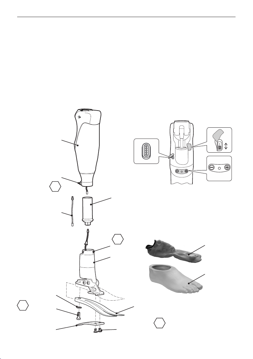
3 Construction
Principal Parts
• Knee Module including pyramid (aluminium/St. Stl./titanium, carbon)
• Ankle Module (aluminium/St. Stl.)
• Pylon (aluminium)
• Heel & Toe Springs (e-Carbon)
• Spring Attachment Screws (titanium/St.Stl.)
• Glide Sock (UHM PE)
• Foot Shell, cables and exi-boards (polymers and PU)
• Batteries (lithium ion)
Toe Spring
Washer
Toe Spring
Screw
(Loctite 243)
Heel
Spring
Heel spring
Screws
(Loctite 243)
Toe
Spring
8
35Nm
4
15Nm
Battery On/O
Switch
[+], [-]
Buttons
and LED
Magnetic
Charging
Terminal
Extension
Cable
4
15Nm
5
10Nm
Clamp
Screw
Glide
Sock
Foot
Shell
938353V2APK3/1-0321

9
The device is a complete external transfemoral
limb prosthesis, which utilizes sensors and
actuators controlled via microprocessors in
an integrated hydro-pneumatic knee and
hydraulic foot system.
The Linx app-based interface programs
the device to the individual user’s gait
characteristics during the Calibration stages
of the set-up sequence. This set-up can then
be ne-tuned to meet specic requirements.
Alternatively, programming can be achieved
via the buttons at the rear of the knee, but
with less ne tuning options than are available
with the app.
The limb provides control of the stance and
swing phase of the user’s gait while the stance
control is optimized to provide secure support
during ambulation on all terrains.
The enhanced stability of the system oers a
Standing Mode with control of knee exion
and ankle for standing.
There is increased ground contact and better
resistance to knee exion during ramp
descent. There is an optimized assistance for
ramp ascent provided by the limb.
It has a dynamic action during stair descent
with an easy start of knee exion coupled
with increasing support to gently lower the
user during exion. It also provides supportive
resistance to exion as soon as the knee stops
exing and increased supportive resistance
to exion to prevent ‘stumbles’ associated
with instability at heel strike. Heel rise during
walking is actively controlled via hydraulic
damping.
The device is powered by a rechargeable
lithium-ion battery pack, charged via a
magnetically secured and self-aligning charger
connection on the posterior of the knee.
4 Function
938353V2APK3/1-0321

10
Limb Operating Modes
Activity Device
Operating
Mode/function
Knee module Foot module
Walking
(level ground)
Normal Alternates stance (high
yield resistance) to free
swing (low resistance) and
pneumatic swing control
adjusts for cadence
variation.
Excessive heel rise is
also actively damped
hydraulically preventing
excessive heel rise
associated with sudden
cadence variation.
Slightly dorsiexed during
swing
Basic resistance settings
in plantarexion and
dorsiexion
Walking up
ramp
(moderate/
steep incline)
Ramp Ascent
Enables easier
walking up
incline.
Progressively changes
hydraulic damping and
pneumatic assist to assist
up the ramp; adjusts for
cadence variation.
Progressively changes* stier
plantarexion and lower
dorsiexion resistance to
assist up the ramp.
Walking down
ramp
Ramp Descent
Helps reduce
forward
momentum and
provides greater
stability and
security.
Moves from a high yield
resistance, through an
intermediate resistance
then to free swing (low
resistance) and adjusts for
cadence variation.
Progressively changes*
decreasing plantarexion
and increasing dorsiexion
resistance to provide a
braking action down the
ramp.
Standing Standing Mode
Increases
stability when
standing still.
Very high resistance in knee and ankle ( activates after
1-1.5 seconds).
Any Low battery
power
High resistance (No
dynamic control)
Reverts to basic
plantarexion & dorsiexion
resistance settings.
(No dynamic control)
*Ramp detection depends on gait, starting, stopping, accelerating and decelerating and any of these can
delay response.
938353V2APK3/1-0321

11
5 Maintenance
A service is required every 36 months.
Maintenance must be carried out by competent personnel.
It is recommended that the following maintenance is carried out annually:
• Remove the foot shell and glide sock, check for damage or wear and replace if necessary.
• Check all screws for tightness (see Section 3), clean and reassemble as necessary.
• Visually check the heel and toe springs for signs of delamination or wear and replace if
necessary. Some surface damage may occur after a period of use;
this does not aect the function or strength of the foot.
The user must be handed the User Guide supplied, and be advised of the following:
Before connecting the charger to the device, always check that the magnetic mating surfaces
of the charging connector and charging terminal are clean, dry and free of debris that could
prevent correct charging operation; if not, clean, dry and remove any debris as necessary before
connection (see Cleaning below).
Any changes in performance of this device must be reported to the clinician.
Changes in performance may include:
• Increase or decrease in knee and/or ankle stiness
• Instability
• Knee starting to extend too aggressively
• Reduced ankle/knee support (free movement)
• Any unusual noise
• Any unrecognized beeps or warning lights.
The user should be advised that a regular visual check of the foot is recommended, signs of wear
that may aect function should be reported to their service provider (e.g. signicant wear or
excessive discoloration from long term exposure to UV).
Cleaning
Use a damp cloth and mild soap to clean outside surfaces, DO NOT use aggressive cleansers.
Ensure water/liquids do not enter the charging socket. Thoroughly dry before use.
To clean the magnetic mating surfaces of the charging connector and charging terminal use a
clean and dry cotton swab or a soft bristle brush. Make sure that no cotton bres or bristles are
left on the surfaces.
Never apply water or any other cleaning liquid to the magnetic mating surfaces.
938353V2APK3/1-0321

12
6 Limitations on Use
Intended life:
A local risk assessment should be carried out based upon activity and usage.
Lifting loads:
User weight and activity is governed by the stated limits.
Load carrying by the user should be based on a local risk assessment.
Environment:
Avoid exposing the device to corrosive elements such as water, acids and other liquids.
Also avoid abrasive environments such as those containing sand for example as these may
promote premature wear.
Keep magnetic or electrically conductive materials away from the magnetic mating surfaces of
the charging connector and charging terminal.
Exclusively for use between -10˚C and 50˚C (14˚F to
122˚F).
938353V2APK3/1-0321
13
7 Battery Charging
Please advise the user of the charging information in this section.
The batteries are not eld replaceable and will be replaced as necessary when serviced.
If the device is subjected to temperatures lower than -10 °C ( 14°F) it must be returned
to be inspected for possible damage to the battery pack.
1. The battery should only be charged in temperatures between 10˚C to 40˚C (50˚F to
104˚F).
2. Only charge the batteries in the device using the charger supplied with the product.
Do not use this charger for charging any other device.
3. The battery charger can be used with an electrical outlet that is rated
between 100V and 240V AC, 50/60Hz.
4. Never connect the charger to the device while still wearing the limb
5. During charging no power is delivered to the device’s control system.
6. The knee module may become warm during charging but should never be too hot
to touch. There should be no unusual smell, if there is immediately switch OFF [O]
the battery, unplug the charger from the electrical supply and contact your service
provider.
7. Do not ret the device until the charger has been disconnected and the device has
completed the full start-up procedure.
8. Always recharge the device before use if it has not been used for an extended period
of time.
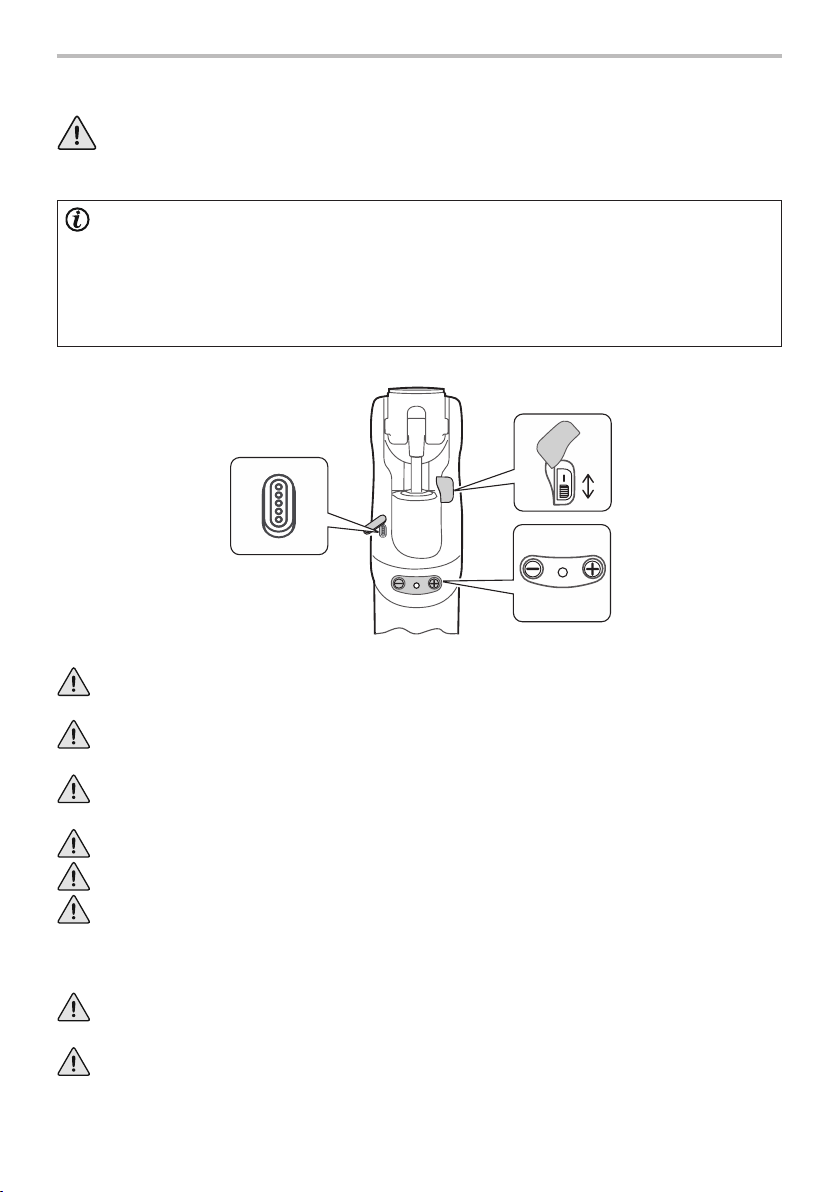
WARNING: The device contains Li-ion type rechargeable batteries. Please
read and comply with the safety information. Failure to do so may cause the
battery to become hot, explode, or ignite and cause serious injury.
Battery
On/O
Switch
[+], [-] Buttons
and LED
Magnetic
Charging
Terminal
938353V2APK3/1-0321

14
7Battery Charging (continued)
Battery
Charger
LED
Battery
Charger
Fully charge the battery before rst use.
We recommend that the device should be fully charged
every night. It should take 8 hours to charge fully (from fully
discharged). We also recommend battery charging whenever
convenient.
Step-by-Step Guide:
1. Lay the limb on a at surface.
2. Ensure the mating surfaces of the magnetic charging
connector and terminal are clean (see Section 5).
3. Magnetically join the charging connector to the charging
terminal at the posterior of the knee and check alignment is
correct (see Section 7.1).
4. Switch the Battery On/O switch to ON [I].
5. Check the Battery Charger LED is ashing green to conrm
the battery is charging.
6. Refer to table below to ensure Limb is charging.
7. Disconnect from the charger when charged suciently.
8. Wait for 30 seconds while observing the device LED
changing color as indicated:
Battery Charger LED Charging State
Yellow Standby
Green > fast ashing Fast charging
Green > slow ashing Close to full charge
Green Maintain (trickle charge)
Yellow > fast ashing Error (Ensure Battery Switch is
ON [I])
Note… If the charger LED is yellow and the Limb is making
a clicking noise check that the Battery switch is in the ON [I]
position.
Device
LED
Red Blue Red Green O
9. After a successful reset sequence, 2 short beeps will be
heard (if this alert is not disabled; see* below).
10.If reset sequence is unsuccessful or the LED remains Red,
switch the battery OFF [O] then ON [I] and repeat from
step8.
*The user can enable or
disable the audible reset
conrmation by pressing
and holding the [ + ] and[-]
buttons simultaneously for 2
seconds. The change will be
conrmed by 2 short beeps.
Note… Do not move
or don the limb while
reset is processing
otherwise this will
prolong the reset
time.
Magnetic
Connector
Device
Device
LED
938353V2APK3/1-0321
15
When fully charged the device’s battery is intended to provide up to 3 days of normal use
(conditional on the type of use). We recommend that the knee be fully charged every night.
Switching o the device when not in use will also prolong the period of use
Note… The device will take 30 seconds to reset after it is switched back ON [I] ; refer to Section 7
‘Battery Charging (continued)’ for the reset sequence.
Battery Charge Indicator
LED Beeps Battery Condition
Green 3 ashes -- fully charged
Green 2 ashes -- good
Green 1 ash -- ok
Yellow slow ash 8 x Short beeps low charge
Red slow ash 5 x Long beeps no charge
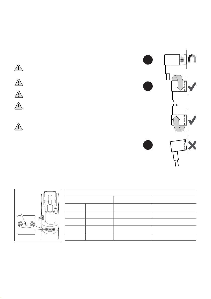
7.1 Magnetic Charger Connection
The charging connector can be connected to the device through the charging terminal located
at the posterior of the knee.
The connector and the terminal magnetically lock together and correctly self-align on
connection (Figure 1).
7.2 Battery Status
To check the battery condition press and hold the [-] button on the knee, one short beep will be
heard and the LED will indicate the battery condition.
Please check for any misalignment between mating surfaces as
this may result in no charging. This can happen especially when
the charging setup puts strain on the charging cable (Figure 3).
Before charging ensure charging surfaces are clean, dry and free
of any debris.
Do not allow any ferrous material to attach itself to the charging
surfaces.
Keep the magnetic surfaces away from materials that may be
adversely aected by their proximity to strong magnetic elds
(e.g. watches, pacemakers, bank cards or magnetically stored
media).
Prevent build up of debris on the charging surfaces as this may
prevent charging or damage the charger. Disconnect the charger
from the mains socket and remove any debris before reconnecting
the charger to the device.
1.
2.
3.
Note… The connector and the terminal are not polarized so
orientation is not critical (Figure 2).
Device
Device
LED
938353V2APK3/1-0321

16
8 Alignment
Knee
module
Pylon
Ankle
module
Extension
cable
Connecting
cable
Clamp Screw
5
10Nm
Set
screws
Grommet
seal
Connecting
cable
The device will need to be adjusted for
the height of the user, and the footwear
to be used.
Follow these instructions to adjust the
length of the pylon in the device.
8.1 Assemble the Complete
Limb
Ensure the connecting cable is not trapped,
carefully slide the knee onto the top of the
pylon tube with a slight twisting action (there
is no need to connect the cable at this stage).
Ensure that the pylon is fully inserted into the
knee housing then align the knee and ankle
and tighten the clamp bolt to 10Nm Torque.
Take the measurement required for the user.
8.2 Adjust the Pylon Length
Undo the clamp screw and taking care not
to damage the connecting cable remove the
Knee module.
To release the pylon undo the 4 pyramid set
screws on the ankle module, carefully ease the
shin cable and grommet from the pyramid and
remove the pylon.
WARNING
Take care not to damage the
internal connecting cable between
the knee and ankle modules when
assembling or disassembling the
device.
938353V2APK3/1-0321

17
Pylon
Cutting Jig
941257
8.3 Cut the Pylon to Length
WARNING
Do NOT attempt to cut the pylon
to length without completely
removing it from the limb.
Failure to do so will result in the
connecting cable being damaged.
Using the pylon cutting jig to hold the pylon
while cutting it to the required length.
Note that using the cutting jig ensures that
the Pylon is not cut shorter than the minimum
recommended length.
De-burr and remove any sharp edges from the
cut end of the pylon and ensure any debris is
cleaned o. De-grease it using a suitable de-
greasing agent.
Clamp Screw
5
10Nm
8.4 Re-assemble the Limb
Connect the shin extension cable to the ankle
module cable (for the shortest pylon the
extension cable will not be required).
To t the pylon to the ankle, thread the
connecting cable through the small hole in
the bottom of the pylon pyramid and gently
push the pylon down into the ankle housing
ensuring it engages the grommet seal.
Tighten the ankle set screws to secure the
pylon.
Lay the ankle and knee at on the work top
and connect the knee module cable to the
ankle module cable.
Taking care not to damage the connecting
cable carefully slide the knee onto the top of
the pylon tube with a slight twisting action.
Align the knee and ankle and tighten the
clamp screw.
938353V2APK3/1-0321

18
6°3°
8.5 Bench Alignment
½½
Build Line
approx. 1/3 2/3
Tilt Setting: Ankle
Set the ankle in 3° dorsiexion and 6°
plantarexion. Check that the ankle is
not on the tilt limits and that the user
is standing in a comfortable upright
position before commencing the dynamic
alignment.
*
Allow for user’s own
footwear
*
Ensure that when the device is in
full exion no part of the socket
or associated componentry
comes into contact with the
knee.
Set the socket in 5° exion plus any
measured exion contracture.
938353V2APK3/1-0321

19
9 Device Set-up
WARNING
Programming should only be carried out by a suitably qualied practitioner.
Incorrect conguration could result in an accident and severe injury.
Prior to setting up a device, install the Linx Programming App on a suitable iOS or Android
programming device, e.g. phone or tablet that supports Bluetooth® (see Appendix 1 for iOS and
Appendix 2 for Android).
The device is set-up, i.e. the limb’s onboard program settings are congured and ne-tuned to
suit a specic user’s requirements, using the oboard Linx Programming App over a Bluetooth®
connection (see Section 9.1).
However if access to the App is unavailable, then the device may be set-up directly using Button
Programming via buttons on the back of the knee (see Section 9.2).
Before setting up the device ensure that the battery is charged and it is switched on.
2. When the welcome screen appears accept
the license agreement and enter your
Password (specied during authorization).
3. Linx Connect screen appears.
4. Make the Bluetooth® connection between
the app and the device (see Section 9.1.2).
First time use of the App shows the following
screen:
These instructions describe how to use the
Linx Programming App to set-up the device
The App is connected to the device via a
Bluetooth® module in the limb.
The App allows the Clinician to:
• Set-up the device for an individual user
• Fine-tune the settings
• View the sensor readings dynamically (via
the Monitor screen)
• Save and restore knee settings.
Setting up a device for the rst time
The device will need to be adjusted to suit
the height of the user and the footwear to be
used, see Section 8.
To launch the Linx Programming
App:
1. Click the app icon on the
home screen.
9.1 Using the Linx Programming App
Program
Do Not Walk No Program
LinxV2 Hub
938353V2APK3/1-0321
Standing Mode
Program
Fine TuneMonitorReview
User Modes
LinxV2 Hub
20
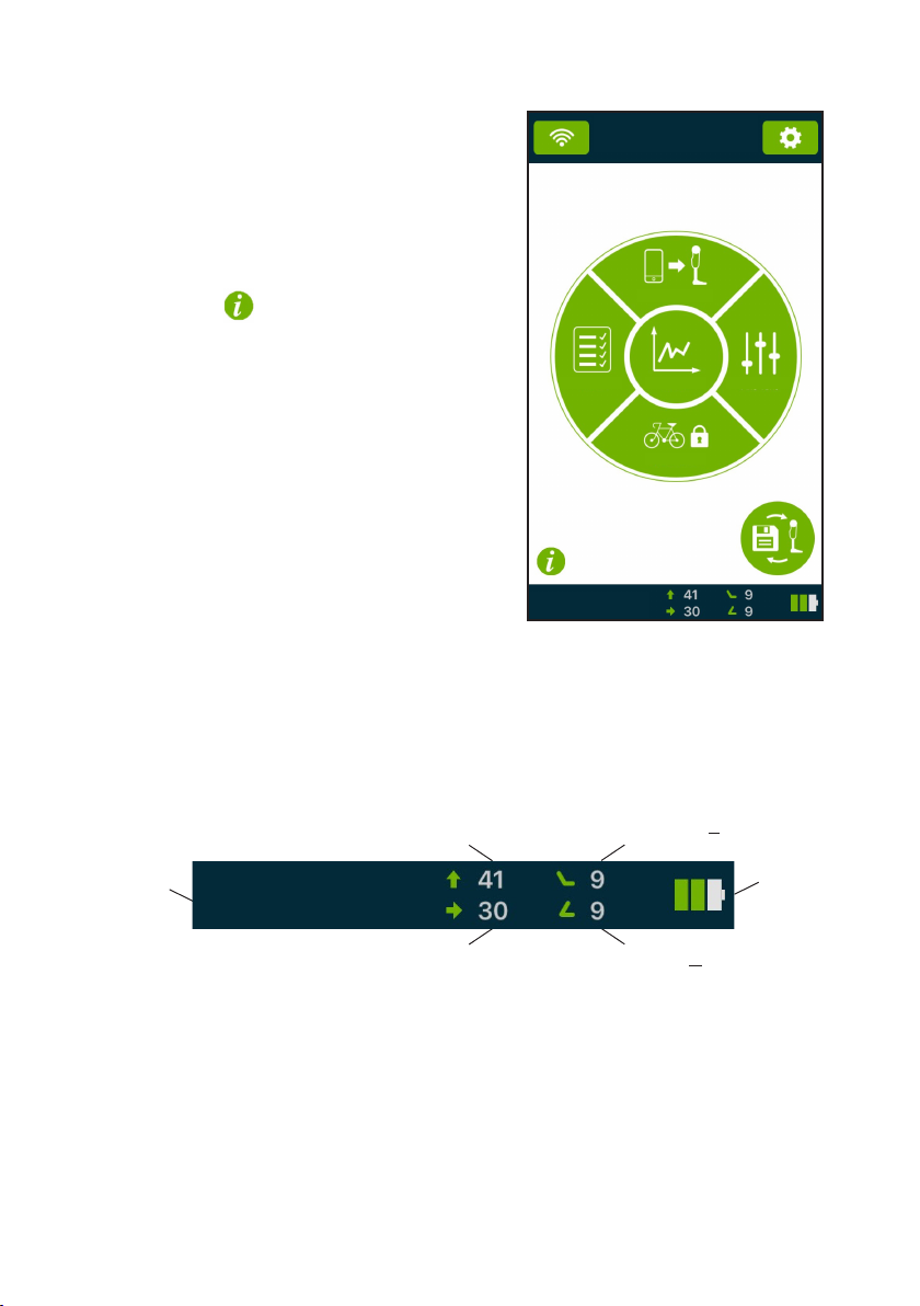
9.1.1 Linx Programming App Screen Layout
Thereafter, the Hub screen will be shown:
The Hub screen provides easy access to
the main sections of the device interface:
[Program], [Fine Tune], [User Modes], [Monitor]
and [Review].
For help tap on the button on the Hub
screen or on the title bar on any screen.
Status Bar
Indicates the device operational mode, yield level, assist level (swing control), plantarexion
level, dorsiexion level and battery level.
Operational
Mode
Yield Level (h41)
Assist Level (Swing Control) (g30)
Battery
Level
Plantarexion Level ( \ 9)
Dorsiexion Level ( / 9)
Standing Mode
938353V2APK3/1-0321
Other manuals for Linx
4
This manual suits for next models
7
Table of contents
Languages:
Other Blatchford Mobility Aid manuals


Popular Mobility Aid manuals by other brands


Clearwell Mobility
Clearwell Mobility Brandon User instructions

Otto Bock
Otto Bock Pheon 3R62 Instructions for use

Concourse
Concourse SMART WHEELS WHEELCHAIR SYSTEM user manual

Rifton
Rifton R123 product manual

Invacare
Invacare Formula parts catalog

lifestyle mobility aids
lifestyle mobility aids H5001 instructions