Concourse SMART WHEELS WHEELCHAIR SYSTEM User manual

SMART WHEELS WHEELCHAIR SYSTEM
USER MANUAL

C O N C O U R S E M A N U F A C T U R I N G
Smart Wheels Wheelchair System (SWWS)
User Manual
©Concourse Manufacturing
9 Hamley Road, Mount Kuring-Gai, NSW 2080, Australia
Phone: 1300 650 059
Email: info@concoursemanufacturing.com
ABN 53 658 807 062

Table of Contents
1 USER ASSISTANCE INFORMATION .........................................1
2 INDICATIONS FOR USE.............................................................2
3 GRAPHICAL SYMBOLS..............................................................3
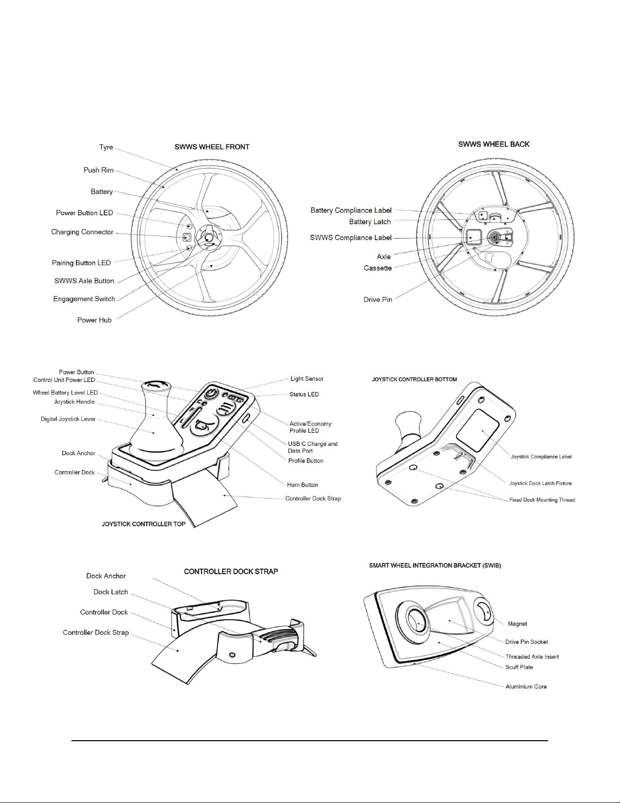
4 DESCRIPTION OF DEVICE ........................................................5
5 ENVIRONMENTAL CONDITIONS THAT AFFECT USE.............6
6 SETUP INSTRUCTIONS.............................................................8
7 INSPECTION OF DEVICE...........................................................9
8 OPERATING INSTRUCTIONS..................................................10
8.1 INSTRUCTIONS FOR USE..............................................................10
8.2 LED INDICATIONS –CONTROL UNIT AND WHEEL.....................12
9 JOYSTICK CONTROLLER INSTRUCTIONS ............................17
10 CHARGING INSTRUCTIONS..................................................21
10.1 CHARGING OF WHEEL BATTERY...............................................21
10.2 CHARGING OF JOYSTICK CONTROLLER..................................22
11 CLEANING...............................................................................23
12 MAINTENANCE.......................................................................24
13 STORAGE AND TRANSPORT................................................25
14 TROUBLESHOOTING.............................................................25
15 WARRANTY, GUARANTEE AND LIABILITY ..........................26
15.1 WARRANTY ...................................................................................26
15.2 GUARANTEE..................................................................................26
15.3 LIABILITY........................................................................................27
16 TECHNICAL DATA..................................................................28
17 LABELS ...................................................................................29
18 DISPOSAL...............................................................................30
19 DATE ISSUED/REVISED ........................................................30

www.concoursemanufacturing.com 1 SWWS User Manual | Version 1.2
1USER ASSISTANCE INFORMATION
DISTRIBUTOR CONTACT INFORMATION
Permobil (Australia)
Address: 8 Viewbrook Close, Seven Hills NSW 2147 Australia
Phone: 1300 845 483
Email: orders.au@permobil.com, techsupport.au@permobil.com,
service.au@permobil.com
STATEMENTS
Please read through the entirety of this manual before attempting to
operate or attach Concourse Smart Wheels.
PLEASE SAVE THESE INSTRUCTIONS

www.concoursemanufacturing.com 2 SWWS User Manual | Version 1.2
2INDICATIONS FOR USE
The Smart Wheels Wheelchair System is a medical device intended to
provide electronic power to manual wheelchairs through a retrofitted
wheel. This enables a user to reduce the manual power needed to move
their wheelchair. Concourse Smart Wheels is primarily for indoor mobility
assistance.
The device is designed for active wheelchair users who have adequate
cognitive and physical ability to safely operate the wheelchair with the
Concourse Smart Wheels attached. This extends to being competent in
all possible conditions, while also having the ability to manually stop and
slow the wheelchair down in the event of the Concourse Smart Wheels
electronic brakes failing.
A user must be instructed in handling and operating the device before
use. A training session should be arranged through a certified Permobil
dealer.
NOTE: Throughout this user manual, the Concourse Smart Wheels
Wheelchair device may be referred to as ‘Concourse Smart Wheels’,
‘Smart Wheels’ or ‘SWWS’.

www.concoursemanufacturing.com 3 SWWS User Manual | Version 1.2
3GRAPHICAL SYMBOLS
TABLE 1: Signs and Symbols Identification
SYMBOLS
WARNING/CAUTION
Warning
A particular instruction or use can be seriously dangerous to one’s
health and safety and/or damaging to the device.
Caution
A particular instruction or use may be potentially hazardous, and
users must exercise careful behaviour.
Tips or special
information
Special Information and tips for proper use.
Disposal
Information for proper disposal of Smart Wheel components.
Medical Device
Indicates a medical device (any device intended to be used for
medical purposes).
Weather
Protect the device from water or moisture.

www.concoursemanufacturing.com 4 SWWS User Manual | Version 1.2
Temperature
Recommended temperature range of Smart Wheels use.
Weight Capacity
The Maximum total weight of a user the Smart Wheels can safely
withstand at any time.
Manufacturing Date
The manufacturing date of the device.
Manufacturing
Name/Address
Name and Address of device manufacturer
Refer to User Manual
Refer to the user manual
Indicates Lithium-Ion Battery
Observe these warning and caution symbols throughout the manual to avoid
physical injury to self and/or damage to the device.

www.concoursemanufacturing.com 5 SWWS User Manual | Version 1.2
4DESCRIPTION OF DEVICE
*Included but not pictured: SWWS Joystick charging cables and Wheels charger.

www.concoursemanufacturing.com 6 SWWS User Manual | Version 1.2
5ENVIRONMENTAL CONDITIONS THAT
AFFECT USE
TABLE 2: Environmental conditions for use of Smart Wheels Device.
CONDITION
INFORMATION
Temperature Range
Optimal: 0-30°C,
Min/Max: –10 - 40°C.
Please Note: Operating at greater than 30°C, may have adverse
effects on motor performance including overheating. Less than
0°C, may have adverse effects on battery performance, with
more frequent charging required.
Ground Type
Avoid using the Concourse Smart Wheels on soft ground such
as loose chips, gravel, mud, ice, wet grass, sand, snow, or deep
puddles. Such conditions may affect performance and may
result in wheelchair toppling over.
Weight Range
Maximum user weight 120kg
Maximum Speed
Max speed 8.5 km/h
Please Note: When travelling on inclines, maximum speed may
vary depending on user weight and slope angle.
Maximum Slope
3°
Tested to 3° slopes, with the capability of climbing steeper
slopes of up to 6° for short distances.
Warning: Please note that when travelling
downhill the maximum speed will be
electronically limited for safety depending on
the gradient of the hill. If user wishes to travel
faster, device can be switched into manual
mode.
Weather Conditions
1. Adapt wheelchair speed for wet ground conditions –wet
wheels may affect grip and result in slipping. Adapt your
driving behaviour accordingly and never drive with worn
tyres.
2. IP 64 Rated –dust tight and water splashes from any
angle.

www.concoursemanufacturing.com 7 SWWS User Manual | Version 1.2
Warnings:
•Do not use Concourse Smart Wheels before you
have been properly instructed on its handling and
operation by a certified dealer.
•Do not use the Concourse Smart Wheels on
escalators or moving walkways.
•Please take caution when travelling around and/or
over railroads or tram tracks.
•Do not submerge wheels under water. Concourse Smart Wheels are
Ingress Protection rated 64, dust tight and water splashes from any
angle. They are not designed for any further liquid ingress including sea
water, temporary submersion, or permanent submersion.
•When not in use, do not expose Concourse Smart Wheels to strong
sunlight for long periods of time. This could cause the motor to heat up
and not be able to operate at full power. The materials of the device may
also discolour and deteriorate quicker when not stored appropriately in a
dark, dry and protected location.
•It is recommended to not use Concourse Smart Wheels without anti-
tippers. The anti-tip device is important for your safety and prevents you
from tipping backwards in case of high acceleration on a steep slope. If
the anti-tip blocks other parts of your own wheelchair, please contact
your dealer. Consult your clinician for an assessment of individual
capability to use device without anti-tippers.
•Using the Concourse Smart Wheels on wet grass, without an adequately
prescribed castor wheel, may affect performance and/or result in chair
toppling over.

www.concoursemanufacturing.com 8 SWWS User Manual | Version 1.2
6 SETUP INSTRUCTIONS
All setup of the Concourse Smart Wheels is to be carried out by a certified
dealer.
SETUP CONFIGURATIONS
1. Smart Wheel Integration Bracket (SWIB)
Smart Wheel Integration Brackets (SWIBs) must be attached by a
certified dealer. The SWIB is a bracket that attaches to your chair for the
Concourse Smart Wheels. Your personal wheelchair must be matched to
a corresponding SWIB in the wheelchairs contained within the
Concourse Bracket Database before use. If a SWIB is not available
through your dealer, inquire about ordering a custom SWIB (fees may
apply).
2. Device Tuning Parameters
Individual tuning of device settings is available through your dealer. It is
recommended that you consult with your occupational therapist or health
care provider to determine correct settings.
Features that can be tuned include:
•Maximum speed forward and reverse
•Deceleration Speed (Harder/Softer)
•Acceleration Speed (Harder/Softer)
•Steering (Faster/Slower) in movement and stationery
•Trim Degree sensitivity
•Dead Band Deflection sensitivity

www.concoursemanufacturing.com 9 SWWS User Manual | Version 1.2
7 INSPECTION OF DEVICE
Prior to operating the Concourse Smart Wheels, please conduct a thorough
inspection of the device for safety:
1. Check brackets are firmly in place on the wheelchair.
2. Check manual wheelchair brakes are free of debris and are functioning
correctly.
3. Check for foreign objects in/around Concourse Smart Wheels battery.
4. Check quick release axle is free of debris.
5. Check the air pressure in the tyre is inflated to between 85-145 psi
(586.054-999.74 Kpa).
•Schwalbe Marathon Plus Tyres: Puncture resistance is maximised
when the wheel is vertical and diminishes with the amount of camber.
•It is recommended to use an automatic pump for tyres to avoid injury.
6. Check there are no cracks or functional faults on device.
7. Check that the batteries are sufficiently charged for operation.
8. Check that magnet on Left SWIB is free of debris.
9. Check joystick can freely move and is free of debris.

www.concoursemanufacturing.com 10 SWWS User Manual | Version 1.2
8OPERATING INSTRUCTIONS
8.1 INSTRUCTIONS FOR USE
There are 9 steps for operating the SWWS:
1. Attach wheels to your chair by sliding the axle into the Smart Wheel
Integration Bracket (SWIB) attached to the chair while pressing down on
the SWWS axle button.
The wheels are not Left and Right specific. They will detect a
magnet in the LHS SWIB and determine left and right once
inserted to the chair, and the battery is attached.
2. Insert battery on each side of the wheel, ensuring ‘click’ of latch is heard.
Wheels will be in a sleep state.
If using a controller dock strap continue reading, otherwise skip to step 4.
If using a fixed wheelchair arm dock, the dock is permanently in
place.
3. Strap controller dock to your preferred arm or leg by wrapping the strap
around your limb, thread through the loop to tighten, and fasten onto the
Velcro.
4. Attach Joystick controller to the dock by sliding the bottom side of device
in first and then lock in place by pushing down on the dock latch to
secure the top side of the controller in place.
5. Manoeuvre yourself into the wheelchair and engage wheelchair parking
brake.
6. Turn on joystick controller: press power button once and a beep will be
heard once the controller connects to the wheels. A lit Control Unit power
LED will also be displayed.
•Ensure joystick is in a neutral vertical position when turning on device,
otherwise device will not start.

www.concoursemanufacturing.com 11 SWWS User Manual | Version 1.2
•Control Unit Power LED will flash white while connecting.
7. Reach down to each wheel and turn the device into powered mode using
the engagement switch.
•To do this, push against the dimpled surface of the switch until it stops
rotating. The direction of rotation will be opposite for LHS and RHS
wheel.
8. Push joystick forward and wait until wheelchair registers drive-pin
engagement, indicated by a short beep and a lit Control Unit power
LED.
•If drive pin is engaged, device will go into economy profile, if drive pin
is not engaged, device will return to freewheel mode.
•If not successful in engaging the drive pin, attempt to re-engage by
repeating step 8. Both wheels must be engaged for joystick control to
be enabled.
9. Wheels are ready for use in power mode, indicated by a solid green LED
displayed on the power and status LEDs.
•When entering Power Mode, the Smart Wheels will go into Economy
profile (solid white profile LED) by default. To switch to Active profile,
press the profile button once (Flashing White profile LED).
•To accelerate in the desired direction of travel, push joystick forward
and then steer in intended direction.
•To decelerate, move joystick back towards centre. If braking on
inclines, Smart Wheels will hold braking position electronically for
1min. If you’d like to stay longer, please engage manual wheelchair
parking brake.
EMERGENCY STOP: In case of emergency, move joystick in
opposite direction of motion –for fast, aggressive braking –or press
down power button.

www.concoursemanufacturing.com 12 SWWS User Manual | Version 1.2
8.2 LED INDICATIONS –CONTROL UNIT AND WHEEL
FIGURE 1: Bluetooth Joystick Controller
TABLE 3: Connected Mode
LED = Light-Emitting Diode
(*) Control Unit displaying Wheel charge level displays wheel with lowest state of charge
CONNECTED MODE LEDS
Unlocked
Locked
Control
Unit
Power
Status
Profile
Battery
Wheel
Battery
Indicator
Control
Unit
Power
Status
Profile
Battery
Wheel
Battery
Indicator
Green
LED
Green
LED
None
*Charge
Level
2 White
LED
White
LED
Green
LED
None
*Charge
Level
2 White
LED

www.concoursemanufacturing.com 13 SWWS User Manual | Version 1.2
TABLE 4: Unconnected Mode
UNCONNECTED MODE LEDs
Control Unit
Wheels
Control
Unit
Power
Status
Profile
Wheel
Battery
Indicator
Buzzer
2 Wheel LEDs
Flashing
White
LED
None
None
None
None
None
TABLE 5: Wheel Battery Level
WHEEL BATTERY LEVEL LEDs
Wheel Battery
Level
Control Unit Wheel
Battery Indicator
Wheel LEDs
Sound
76-100%
3 Green LEDs
2 White LEDs
None
16-75%
2 Yellow LEDs
2 White LEDs
None
5-15%
1 Yellow LED
2 Yellow LEDs
Beep
<5% Critically Low
1 Flashing Yellow LED
2 Flashing Yellow
LEDs
Beep

www.concoursemanufacturing.com 14 SWWS User Manual | Version 1.2
TABLE 6: Charging
CHARGING DEVICE LEDs
Control Unit Charging
Wheel Charging
Control
Unit
Power
Status
Profile
Wheel
Battery
Indicator
Control
Unit
Power
Wheel LEDs
Control Unit
Wheel Battery
Indicator
None
2 Flashing
Purple LEDs
3 Flashing
Purple LEDs
Flashing
Purple
LED
None
None
None
Fully Charged, Plugged In
Purple
LED
None
None
None
None
2 Purple
LEDs
3 Purple LEDs

www.concoursemanufacturing.com 15 SWWS User Manual | Version 1.2
TABLE 7: Error Messages
ERROR MESSAGE LEDs
Motor Fail
Control Unit
Wheel/s
Status
Profile
Control Unit
Power
Wheel Battery
Indicator
2 Flashing Red
LEDs + Loud
Irregular Beep
Flashing Red
LED + Loud
Irregular Beep
None
Locked (White
LED) /Unlocked
(Green LED)
*Charge Level
Wheel Latching Issue
Control Unit
Wheel/s
Status
Profile
Control Unit
Power
Wheel Battery
Indicator
2 Solid Cyan LEDs
Solid Cyan
LEDs + Beep
None
Locked (White
LED) /Unlocked
(Green LED)
*Charge Level
System Error
Control Unit
Wheel/s
Status
Profile
Control Unit
Power
Wheel Battery
Indicator
2 Flashing Yellow
LED + Beep
Flashing Yellow
LED + Beep
Flashing
Yellow LED
None
None
Please Note:
•Flashing Red LED = take device to your nearest Permobil Dealer for analysis –DO
NOT ATTEMPT TO USE DEVICE.
•Yellow LED = Safety Warning; observe indication and take necessary steps to
remediate issue by visiting the troubleshooting section of this user manual.

www.concoursemanufacturing.com 16 SWWS User Manual | Version 1.2
TABLE 8: SWWS Profiles (Mode/Profile Button)
SWWS PROFILES
Economy (Default Profile)
Active
Control Unit Power
Profile LED
Control Unit Power
Profile LED
Locked = White LED
White LED
Locked =
White LED
Flashing White
LED
Unlocked = Green
LED
Unlocked = Green
LED
Cruise Control (In selected Profile)
Same as above
Purple LED
Same as above
Flashing Purple
LED
Wheel Errors
•Displayed on joystick controller and wheel/s with error
•Error will be specific to a wheel, indicated by matching error LED on the
wheel.
•Technician may have access to more specific errors
Both LEDs on a single wheel will always be the same colour –
this is a safety feature if one LED is covered by a spoke.

www.concoursemanufacturing.com 17 SWWS User Manual | Version 1.2
9JOYSTICK CONTROLLER
INSTRUCTIONS
There are 9 instructions for joystick use:
1. Fasten the controller dock to preferred leg with leg dock strap, or to a
fixed chair dock.
2. Ensure that the joystick controller is firmly secured in the controller dock.
If control unit is removed from dock, the SWWS will be locked.
3. Press power button once.
4. The device will be in freewheel mode by default.
5. To use device, push joystick forward until single beep is heard and green
LEDS on the power and the status indicate drive pin is engaged. Device
is now ready to be operated.
6. To move wheelchair, push joystick in desired direction of travel.
•The further down the joystick controller is pushed, the faster the
speed (forward and reverse).
•When stationary, pushing joystick left and right will turn wheelchair on
the spot. Anything in between will steer toward that direction.
7. To reduce speed, bring joystick closer to the centre vertical line.
8. To stop motion, let joystick controller return to centre. To stop quickly,
apply pressure to joystick in the opposite direction of travel (forward or
reverse).
9. To lock device when stationary, press power button and engage manual
parking brake. You can also use this as an emergency brake when not
stationary.
Table of contents
Popular Mobility Aid manuals by other brands

Essential Medical Supply
Essential Medical Supply ENDURANCE P1410R Installation

Permobil
Permobil LapStacker XD Power installation guide

Faaborg Rehab Technic
Faaborg Rehab Technic Click & Go Series user manual

Invacare
Invacare Comfort-Mate Extra / Comfort-Mate Extra Base Installation and operating instructions

Petermann
Petermann Alpha PM-6013 manual

essential
essential FREE Spirit P4000 manual