BleBox Tempsensorpro User manual

tempsensorpro
MINIATURE TEMPERATURE SENSOR WITH EXTERNAL ANTENNA
Improper connections may be dangerous, it can damage
the controller, and loss of the warranty.
Disconnect supply voltage circuit before installing the controller.
Remember that any mounting works should be carried out when
the main voltage is disconnected (switch o the mains fuse or
disconnect the power supply from the socket).
The controller should be installed in a place protected against
accidential destroyment. The measurement probe is waterproof. It
is not allowed to install the probe in a place exposed to contact
with oils, liquid fuels, solvents and caustic substances, as well as in
places exposed to the direct action of high temperatures. Remem-
ber that metallic elements (wires, large tting elements) have a
negative inuence on the range of the device, and consequently
the comfort of use. It is recommended that the device be mounted
in a stable and xed position with the antenna upside. When
installing the device outside of dry rooms, pay special attention to
provide tightness of the rubber cable glands.
Read the diagram and then proceed to install the controller. Pay
particular attention to the designation of the controller connec-
tors. Start by connecting (from left) the GND (black) and
+12V/+24V power wires (red or black with a white dotted line).
A digital probe was used to measure the temperature. It is not
recommended to extend the original temperature probe cable
excessively since the induced interference can cause the controller
malfunction or even damage it.
Than connect the external temperature probe, in the order of wire
colors (from left): black, red and yellow or white, brown and green.
If the additional probes ares also installed they must be connected
in parallel. The last connector, on the far right, must be left uncon-
nected, it has been designed to allow the expansion of the
capabilities of the product and is currently not used.
After making sure that the device is connected in accordance with
the diagram and that there are no metal components near the
controller which may accidentally cause short-circuit, start the
device by turning on the power (turning on the mains fuse or
connecting the power cord to the power outlet).
DANGER! Risk of electric shock! Even with the device
turned o, the outputs may be live. All assembly work
should be ALWAYS performed with the disconnected
power circuit.
The installation of the device to a power mains that does
not meet the quality requirements dened by EN 50081-1,
EN 50082-1, UL508, EN 60950, will result in the loss of the
warranty.
SAFETY RULES
INSTALLATION - BASICS
temperature sensor with
the μWiFi technology
CONNECTION DIAGRAM
max 4 sensors
User manual
+
-
Download the free wBox application. If you have an Android mobile
device, you will nd the application in the Play Store. For iOS devices
the application is in the App Store.
By using your mobile phone or tablet, connect it to the device
wireless network. To do this, enter to your smartphone or tablet
settings, then go to setting of the WiFi network and nd the
network name „tempSensor_PRO-xxxxxxxxxx” where xxxxxxxxxx is
the serial number of the device. Connect to this network.
Open the wBox application. A device will appear at the top of the
screen. To add it to the application, click on "+" on the right side of
the name. To precongure the controller, click on the default device
name.
You can disable the individual sensor display on the main screen by
setting the "Sensor on" option to "No". In the "Name" eld, set a
friendly name for the sensor, eg. "air temperature".
The "Probe" table displays a list of found probes with the current
temperature values. To recognize the probes heat one of them e.g.
by holding it in your hand. Refresh the temperature readings by
pressing the button with two arrows .Select from the list the probe
you want to assign to the given sensor.
The "Temperature value shift" option allows to correct the tempera-
ture reading from the probe by a constant value. Settings can be
made with a slider or by lling a value in the eld. This option is
useful in case of unusual probe installation when it turns out that
the probe lowers or increases the real temperature. Default: 0°C.
Conrm the settings by clicking the "Save" button just below.
The controller allows you to send control commands to other
controllers of the wBox series through the home WiFi network,
through the so-called API, which allows you to build eg. a tempera-
ture control system.
When editing actions, select "Control other device" as the "Action
type", select "Temperature higher than" or "Temperature lower
than" as the "Trigger". In the "Trigger parameter" eld, enter the
temperature limit value, expressed in degrees Celsius, by which,
after being reached, the action will be triggered, e.g. "20". Selecting
the "Do not trigger more often than" option will trigger the action at
every specic time, set in the "Value in minutes" eld, throughout
the period of the exceeded value.
Click on the "Select device" button. The controller will search the
network for compatible devices and display them in a list. Select the
device you want to control and click the "Select" button. If the
device is not listed you must use the general API control method
described further.
Then in the "Call API" eld enter the API command that the driver
will call.
The most popular API commands for switchBox and shutterBox are
presented below. It was assumed that the IP address of the device
which will be controlled is: 192.168.1.123
Switching on the radiator via switchBox: http://192.168.1.123/s/1
Switching o the radiator via switchBox: http://192.168.1.123/s/0
Opening the roller shutter via shutterBox: http://192.168.1.123/s/u
Closing the roller shutter via shutterBox: http://192.168.1.123/s/d
If the device was not on the found list or you want to control another
device in the network, select "Call URL" as "Action type".
In the "URL" eld, enter the API command preceded by the http
protocol prex and the IP address of the wBox device which will be
controlled. The IP address can be found in the device settings.
Caution! All the controllers must be in the same subnet, usually the
subnet of a home router.
Conrm the entry with the "Save" button.
The main screen of the controller shows the current temperature
readings from individual probes, below there is a trend indicator for
its changes.
Historical measurement data is available by clicking on the diagram
icon in the upper right corner of the screen which is displayed only
when the device has access to the Internet - the data are stored only
on the BleBox server.
Historical measurement data can be exported for further analysis.
The export form will be displayed after clicking on the cloud icon in
the upper right corner of the screen.
Go to the conguration ("Settings" icon in the upper right corner of
the screen). In the "Main conguration" section, you can change the
name of the device that is displayed in the wBox application. The
"Status LED enabled" option allows you to turn o the built-in LED
on the device.
To communicate with the device from outside the local Wi-Fi
network, from anyplace in the world, through the wBox application,
the option "Enable remote access" must be set to "Yes". Selecting
the option "Yes" also means accepting to send measurement data to
blebox.eu server in order to process them and archive them togeth-
er with the location. Setting this option to "No", will cause no access
to the controller from outside the internal network or access to the
historical data; it will only be possible to obtain a visualization of the
current values.
Setting the "Enable event log" option to "Yes" will cause the device
to record events (e.g. sending the notication set in the "Actions"
section) in the BleBox cloud system. This allows the history of the
events to be viewed later also when the controller is oine.
In the "Sensors" section, you can congure the temperature probes
connected to the device. The probes are detected automatically
after the rst power connection and assigned, based on identiers,
to individual tabs that represent a given sensor (or rather its place of
installation, e.g. water temperature, air temperature, etc.). Further
conguration is carried out independently for each of the connect-
ed probes, on individual tabs.
ACTIONS / TEMPERATURE REGULATOR
FIRST START
MEASURING DATA
MEASURING DATA
The temperature regulator requires a hysteresis
conguration, it means, a certain dierence
between the switch on temperature and the switch
o temperature. In the case of the radiator control,
the switch on temperature must be lower than the
switch o temperature, e.g. "Temperature lower
than: 19°C, action: turn on", "Temperature higher
than 21°C, action: turn o".
You can also set the conguration using the web
browser of your phone / tablet. After connecting to
the wireless network of the controller, turn on the
browser and go website www.blebox.eu
A detailed description of how to control other controllers of the
wBox series is available in the "Extended instructions for wBox
devices", while all the technical documentation API of the wBox
controllers is available at: http://technical.blebox.eu 12 - 24V
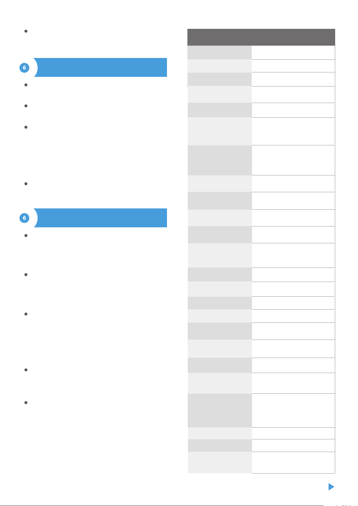
from -55°C to 125°C
from -20°C to 50°C
± 0,5°C in the range of -10°C to 85°C
50 x 92 x 28 mm (without antenna),
85 x 230 x 28 mm (with the antenna
located vertically), antenna
length197 mm
plastic, covered with a polyurethane
composition not containing halogens,
self-extinguishing for thermal class B
(130°C)
diameter 6 mm, length 51 mm
single wired waterproof probe,
cable length 2m
yes, available as an accessory
4
two oval mounting holes with
dimensions of 18 mm x 3,5 mm (width x
height) or self-adhesive element (tape)
IP54
inverted polarization, ESD
< 1W
The controller allows you to display a system notication on a
phone with the wBox application installed on the particular trigger,
e.g. "Temperature higher than".
Notications are added similarly to "Actions" - as "Action type" select
"Notication", ll in the remaining elds of the form and conrm
with the "Save" button.
In order for the notication to be displayed on the phone it is
necessary to allow the controller to display notications. Go to the
main menu of the wBox application, to the "Notications" tab. Then
go to the settings (the "Settings" icon in the upper right corner of
the screen). Find the device on the list and select "Action notica-
tion" from the drop-down list next to the device name. You can also
select other types of available notications or μPortal notications.
Conrm the change of preferences with the "Save" button in the
upper right corner of the screen.
If notications are not displayed despite their conguration check in
the phone system settings (Android/iOS) whether the wBox
application is authorized to display system notications.
Go to "Connect to WiFi network" section, where you can connect the
device to the WiFi home network to be able to connect to it via it or
from anyplace in the world. To do this, select the network name
from the list and press "Connect". If required, enter the WiFi network
password. When connecting the device to the home network, the
phone / tablet may be disconnected from the device's network.
After reconnecting the phone to the controller's WiFi network,
check the "WiFi Client status" and "Remote access status" elds. The
controller is equipped with a network connection supervision
system which in case of problems with connection to the WiFi or the
Internet will report the problem and its possible causes. If the
network is working properly both elds will be set to "Connected".
After completing the WiFi network conguration, you can discon-
nect from the device network and connect the phone / tablet
directly to your home WiFi network. Control from the wBox applica-
tion will work in the same way as when the phone / tablet is
connected to the device's network. If as a user you leave the local
network, eg leaving your home or enclosing mobile data, the wBox
application will signal this status as "Remote mode". In this case, you
will have access to the device data, but for security reasons settings
options will not be available.
In the "Access point settings" section, you can change the name and
give the password of the WiFi network emitted by the device.
Remember that changing the network name or password can cause
disconnection with the device immediately after clicking the "Save"
button, so you should reconnect to the WiFi network.
It is also possible to completely disable the Access Point emitted by
the device. To do this, uncheck the "Access point enabled" eld and
conrm your selection with the "Save" button. Attention! If the
controller does not have a stable connection to the WiFi network
("WiFi client status": "Connected", without any error warnings),
turning the access point back on will not be possible - in this
situation, the only solution is to reset the controller to factory
settings. Disabling the access point is recommended only after the
complete device conguration and making sure that the entire
system is working properly.
NOTIFICATIONS
ACCESS POINT AND WIFI NETWORK
SETTINGS
power supply
energy consumption
measurement range
controller operating
temperature
measurement accuracy
dimensions
housing
dimension of the probe
type of probe
additional probe
maximum number
of connected probes
mounting method
protection level
yes
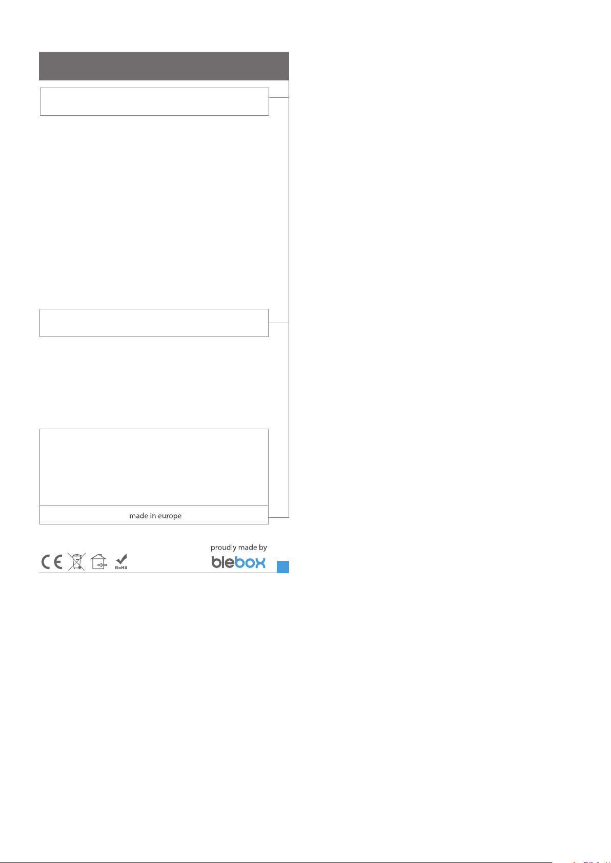
antenna output
protection
RP-SMA
omnidirectional, 5dB gain - included
in the kit
antenna
antenna connector type
μWiFi, compatible with WiFi, 802.11g
bi-directional,
encrypted
transmission type
communication standard
WPA2-PSK and authenticated
encryption with associated data
(AEAD)
direct connection (as Access Point),
Wi-Fi connection via a stan- dard router,
connection with access from any
location in the world (requires only
access to the Internet)
modes
encryption
2.4 GHzradio frequency
open
API
Apple iPhone, Apple iPad, iPad Mini,
Android, computers and mobile
devices supporting HTML5
compatible devices
and systems
TECHNICAL SPECIFICATIONS
To be able to use historical data, it is necessary to set the clock and
location of the device. Go to the "Device time" section of the
settings and then click "Change zone". Select your region and
locations from the list, conrming your selection with the "Save"
button. The device will synchronize its time with the time server (if
the controller is in a WiFi network with Internet access) or it will
download time from the phone/tablet.
Next, in the "Device location" section, click "Set locations". The
application will ask whether to share locations - allow. In the
"Coordinates" eld, the approximate coordinates of your location
should appear. If the "Set locations" button blinks red with the word
"error" or the "Coordinates" eld did not change the value from "Not
set" to numeric data, a failure occurred in the location download.
You should then make sure that the phone / tablet has a GPS
module and that the location sharing support is enabled on the
phone.
LOCATION AND TIME OF THE DEVICE
ADDITIONAL INFORMATION
for more information visit our website
www.blebox.eu
SOFTWARE UPDATE
To update the software in the controller, connect it to your home WiFi network
(see "Access Point and WiFi settings" section) which is connected to the
Internet. Go to “Settings” (icon at the top-right corner of the screen) and click
the "Get new rmware" button in the nal section on settings. Wait about 1
minute, do not close the interface and don’t perform other actions. The device
will download the latest software. The software version number, hardware
version and device identier can be read at the bottom of the settings screen.
Other BleBox Accessories manuals

Popular Accessories manuals by other brands


LU-VE
LU-VE F31HC Series Installation, Operation, Service and Maintenance Instructions

KMC Controls
KMC Controls STE-6014 Application guide

Leuze electronic
Leuze electronic HRT 25B Long Range quick start guide

HoMedics
HoMedics COMFORT PRO TRANSFORM HCM-T210GYQVC-GB instruction manual

Tripp Lite
Tripp Lite UPB-20K0-2U1C owner's manual

HumanTechnik
HumanTechnik lisa operating instructions