KMC Controls STE-6014 User guide

STE-6014/6017/6018/6019/6020 Room Temperature Sensors 1 Application Guide, AN0412B Rev. B
Application Guide
Room Temperature Sensors (with Rotary Dials)
STE-6014/6017/6018/6019/6020
Models
NOTE: For more product information, see the STE-
6000 Series Room Temperature Sensors/
Transmiers Data Sheet on the KMC
Controls web site.
KMD-5624
Cable
KMD-5576
PC Port Network Connection
NOTE: For mounting and wiring information,
see the STE-6014/6017/6018/6019/6020
Installation Guide.
Contents
Models ...........................................................................1
PC Port Network Connection.........................................1
Controller Configuration................................................2
Overview....................................................................2
BACstage Software .....................................................2
BAC-A1616BC BACnet Building Controller................6
TotalControl Software ................................................6
WinControl Software..................................................7
Mounting Considerations ...............................................9
Troubleshooting .............................................................9
Accessories ....................................................................9
Specifications.................................................................9
Important Notices..........................................................9
STE-6014 STE-6018/6020
STE-6017/6019
At the boom of the STE-6014/6017/6018 case is
an EIA-485 (formerly RS-485) computer port. This
port provides a temporary connection to the digital
network for network setup or troubleshooting.
To use the port to connect to a computer, a means of
converting the EIA-485 signal to a USB or EIA-232
(formerly RS-232) signal will be needed. The exact
connection depends on the computer and the opera-
tor workstation software. (See also the instructions
included with those devices and software.)
• For USB (to WinControl or BACstage), use a
KMD-5576 USB Communicator (see the illustra-
tion above).
• For EIA-232 to BACstage, use a third-party
interface.
• For EIA-232 to WinControl, use a KMD-5559
CommTalk and KMD-5624 cable (or equivalent
interface).
To access the network through the STE’s sensor:
1. Connect the keyed, at end of the KMD-5624
interface cable (included with the KMD-5576 but
not the KMD-5559) to the port on the sensor.
2. Connect the other end of the cable to the interface
device that converts the EIA-485 signal into an
EIA-232 or USB signal.
3. Connect the suitable cable from the interface
device to the computer’s serial or USB port. Install
any required software and congure the port as
necessary.
Model
Number
Interface
Features
Cable
Connections
Override
Button
LED
Status
Indicator
Screw
Clamp
Terminals
RJ-45
Connector
EIA-485
Data
Port
STE-6014 X X
STE-6017 X X X
STE-6019 X X
STE-6018 X X X X
STE-6020 X X X

STE-6014/6017/6018/6019/6020 Room Temperature Sensors 2 Application Guide, AN0412B Rev. B
Controller Configuration
Overview
Ensure that the corresponding 10,000 ohm pull-up
resistors on the controller are selected (switched
On). Consult the controller’s setup instructions for
information on switching on the pull-up resistors.
Controller conguration instructions are given for
both WinControl and BACstage. See the relevant
software section.
BACstage Software
Thermistor Input
1. In the BACstage software main menu, select
Objects > Inputs.
2. Click Edit.
3. Type in a name in the appropriate Description
eld (up to 32 characters) and/or Name eld (up
to 16 characters).
NOTE: No two labels or descriptions in a controller
can be identical.
4. Select Object Type: Analog if it is not the default.
5. Select Device Type: KMC10K Type II.
6. Select Units: °F or °C.
7. Optionally, change the Filter Weight (under More)
to the desired number of thermistor readings
averaged before displaying the result. If the
(STE-6017/6018/6019/6020) override is being
used, Filter Weight may need to be reduced
down toward 1 to ensure reliable recognition of
the buon press, depending on the controller.
NOTE: The buon needs to be pressed and held
for at least a half a second to be reliably
recognized for override mode.
8. Click End Edit.
9. Click Yes for “Send Update Notication Now?”
10. In the BACstage software main menu, select
Device > Device Tables > KMC10K Type II Table.
11. Click Edit.
12. Click Defaults (values will ll in).
13. Click End Edit.
14. Click Yes for “Send Update Notication Now?”
15. Click OK.
Setpoint Input
NOTE: The Custom Input property or Control
Basic can be used as easier but less linear
(less accurate) alternatives to tables.
Download the STE-6014/17/18/19/20
Setpoint Dial Ranging Tech Tips Tech
Tips le from the web site.
1. In the BACstage software main menu, select
Objects > Inputs.
2. Click Edit.
3. Type in a name in the appropriate Description
eld and/or Name eld.
4. Select Object Type: Analog if it is not the default.
5. Select Device Type > Table x (4 or 5).
6. Select Units: °F or °C.
7. Click End Edit.
8. Click Yes for “Send Update Notication Now?”
9. In the BACstage software main menu, select
Device > Device Tables > Table x.
10. Click Edit.
11. Enter the following values in Table x:
NOTE: Instead of typing in the values from the
table below, you can use a text editor and
the table on page 5 of the Adobe Acrobat
PDF le of this document to copy and
paste the 128 lines into the appropriate
section of the BACstage *.BAC panel le.
See the instructions on page 4.
Index °FValue °C Value
154.0 12.2
254.3 12.4
354.6 12.6
454.9 12.7
555.2 12.9
655.5 13.1
755.8 13.2
856.1 13.4
956.4 13.6
10 56.7 13.7
11 57.1 13.9
12 57.4 14.1
13 57.7 14.3
14 58.1 14.5
15 58.4 14.7

STE-6014/6017/6018/6019/6020 Room Temperature Sensors 3 Application Guide, AN0412B Rev. B
16 58.8 14.9
17 59.1 15.1
18 59.5 15.3
19 59.9 15.5
20 60.3 15.7
21 60.7 15.9
22 61.1 16.2
23 61.5 16.4
24 61.9 16.6
25 62.3 16.8
26 62.7 17.1
27 63.2 17.3
28 63.6 17.6
29 64.1 17.8
30 64.5 18.1
31 65.0 18.3
32 65.5 18.6
33 66.0 18.9
34 66.5 19.2
35 67.0 19.4
36 67.5 19.7
37 68.1 20.1
38 68.6 20.3
39 69.2 20.7
40 69.8 21.0
41 70.4 21.3
42 71.0 21.7
43 71.6 22.0
44 72.2 22.3
45 72.9 22.7
46 73.5 23.1
47 74.2 23.4
48 74.9 23.8
49 75.6 24.2
50 76.3 24.6
51 77.1 25.1
52 77.8 25.4
53 78.6 25.9
54 79.4 26.3
55 80.3 26.8
56 81.1 27.3
57 82.0 27.8
58 82.9 28.3
59 83.8 28.8
60 84.8 29.3
61 85.8 29.9
62 86.8 30.4
63 87.8 31.0
64 88.9 31.6
65 90.0 32.2
66 90.0 32.2
67 90.0 32.2
68 90.0 32.2
69 90.0 32.2
70 90.0 32.2
71 90.0 32.2
72 90.0 32.2
73 90.0 32.2
74 90.0 32.2
75 90.0 32.2
76 90.0 32.2
77 90.0 32.2
78 90.0 32.2
79 90.0 32.2
80 90.0 32.2
81 90.0 32.2
82 90.0 32.2
83 90.0 32.2
84 90.0 32.2
85 90.0 32.2
86 90.0 32.2
87 90.0 32.2
88 90.0 32.2
89 90.0 32.2
90 90.0 32.2
91 90.0 32.2
92 90.0 32.2
93 90.0 32.2
94 90.0 32.2
95 90.0 32.2
96 90.0 32.2
97 90.0 32.2
98 90.0 32.2
99 90.0 32.2
100 90.0 32.2
101 90.0 32.2
102 90.0 32.2
103 90.0 32.2
104 90.0 32.2
105 90.0 32.2
106 90.0 32.2
107 90.0 32.2
108 90.0 32.2
109 90.0 32.2
110 90.0 32.2
111 90.0 32.2
112 90.0 32.2
113 90.0 32.2
114 90.0 32.2
115 90.0 32.2
116 90.0 32.2
117 90.0 32.2
118 90.0 32.2
119 90.0 32.2
120 90.0 32.2
121 90.0 32.2
122 90.0 32.2
123 90.0 32.2
124 90.0 32.2
125 90.0 32.2
126 90.0 32.2
127 90.0 32.2
128 90.0 32.2
12. Click End Edit.
13. Click Yes for “Send Update
Notication Now?”
14. Click OK.
NOTE: These tables are dierent from the ones used in the STE-6012/6016!

STE-6014/6017/6018/6019/6020 Room Temperature Sensors 4 Application Guide, AN0412B Rev. B
NOTE: Instead of manually entering all the
setpoint table values, you can copy them
from the PDF le of this document.
X1=54.0
X2=54.3
X3=54.6
X4=54.9
X5=55.2
X6=55.5
X7=55.8
X8=56.1
X9=56.4
X10=56.7
X11=57.1
X12=57.4
X13=57.7
X14=58.1
X15=58.4
X16=58.8
X17=59.1
X18=59.5
X19=59.9
X20=60.3
X21=60.7
X22=61.1
X23=61.5
X24=61.9
X25=62.3
X26=62.7
X27=63.2
X28=63.6
X29=64.1
X30=64.5
X31=65.0
X32=65.5
X33=66.0
X34=66.5
X35=67.0
X36=67.5
X37=68.1
X38=68.6
X39=69.2
X40=69.8
X41=70.4
X42=71.0
X43=71.6
X44=72.2
X45=72.9
X46=73.5
X47=74.2
X48=74.9
X49=75.6
X50=76.3
X51=77.1
X52=77.8
X53=78.6
X54=79.4
X55=80.3
X56=81.1
X57=82.0
X58=82.9
X59=83.8
X60=84.8
X61=85.8
X62=86.8
X63=87.8
X64=88.9
X65=90.0
X66=90.0
X67=90.0
X68=90.0
X69=90.0
X70=90.0
X71=90.0
X72=90.0
X73=90.0
X74=90.0
X75=90.0
X76=90.0
X77=90.0
X78=90.0
X79=90.0
X80=90.0
X81=90.0
X82=90.0
X83=90.0
X84=90.0
X85=90.0
X86=90.0
X87=90.0
X88=90.0
X89=90.0
X90=90.0
X91=90.0
X92=90.0
X93=90.0
X94=90.0
X95=90.0
X96=90.0
X97=90.0
X98=90.0
X99=90.0
X100=90.0
X101=90.0
X102=90.0
X103=90.0
X104=90.0
X105=90.0
X106=90.0
X107=90.0
X108=90.0
X109=90.0
X110=90.0
X111=90.0
X112=90.0
X113=90.0
X114=90.0
X115=90.0
X116=90.0
X117=90.0
X118=90.0
X119=90.0
X120=90.0
X121=90.0
X122=90.0
X123=90.0
X124=90.0
X125=90.0
X126=90.0
X127=90.0
X128=90.0
X1=12.2
X2=12.4
X3=12.6
X4=12.7
X5=12.9
X6=13.1
X7=13.2
X8=13.4
X9=13.6
X10=13.7
X11=13.9
X12=14.1
X13=14.3
X14=14.5
X15=14.7
X16=14.9
X17=15.1
X18=15.3
X19=15.5
X20=15.7
X21=15.9
X22=16.2
X23=16.4
X24=16.6
X25=16.8
X26=17.1
X27=17.3
X28=17.6
X29=17.8
X30=18.1
X31=18.3
X32=18.6
X33=18.9
X34=19.2
X35=19.4
X36=19.7
X37=20.1
X38=20.3
X39=20.7
X40=21.0
X41=21.3
X42=21.7
X43=22.0
X44=22.3
X45=22.7
X46=23.1
X47=23.4
X48=23.8
X49=24.2
X50=24.6
X51=25.1
X52=25.4
X53=25.9
X54=26.3
X55=26.8
X56=27.3
X57=27.8
X58=28.3
X59=28.8
X60=29.3
X61=29.9
X62=30.4
X63=31.0
X64=31.6
X65=32.2
X66=32.2
X67=32.2
X68=32.2
X69=32.2
X70=32.2
X71=32.2
X72=32.2
X73=32.2
X74=32.2
X75=32.2
X76=32.2
X77=32.2
X78=32.2
X79=32.2
X80=32.2
X81=32.2
X82=32.2
X83=32.2
X84=32.2
X85=32.2
X86=32.2
X87=32.2
X88=32.2
X89=32.2
X90=32.2
X91=32.2
X92=32.2
X93=32.2
X94=32.2
X95=32.2
X96=32.2
X97=32.2
X98=32.2
X99=32.2
X100=32.2
X101=32.2
X102=32.2
X103=32.2
X104=32.2
X105=32.2
X106=32.2
X107=32.2
X108=32.2
X109=32.2
X110=32.2
X111=32.2
X112=32.2
X113=32.2
X114=32.2
X115=32.2
X116=32.2
X117=32.2
X118=32.2
X119=32.2
X120=32.2
X121=32.2
X122=32.2
X123=32.2
X124=32.2
X125=32.2
X126=32.2
X127=32.2
X128=32.2
Fahrenheit Values Celsius Values
Setpoint Tables to Copy into BACstage Panel File
1. In the BACstage software main menu, select
Device > Backup Device.
2. Enter a le name for the BAC backup le, and
click Save.
3. Make a copy of the BAC backup le, open the
copied BAC le with a text editor, and nd the
Table (previously chosen) 4 or 5 listing (scroll
about half-way down).
4. Open the PDF le of this document and copy the
appropriate table below.
5. Replace the appropriate BAC table data with the
PDF table data and save the le.
6. In the BACstage software main menu, select
Device > Restore Device.
7. Select the edited copy of the BAC le and click
Open.
8. Click Select None,select the appropriate table from
the list, and click Restore.
9. Click Yes for “Send Update Notication Now?”

STE-6014/6017/6018/6019/6020 Room Temperature Sensors 5 Application Guide, AN0412B Rev. B
Setpoint Variable
1. In the BACstage software main menu, select
Objects > Analog Values.
2. Click Edit.
3. Type in a name in the appropriate Description
eld and/or Name eld.
4. Click in the Units column and select °F
(Fahrenheit) or °C (Celsius).
5. Click End Edit.
6. Click Yes for “Send Update Notication Now?”
7. Click OK.
Override (STE-6017/6018/6019/6020 Only)
1. In the BACstage software main menu, select
Objects > Binary Values.
2. Click Edit.
3. Type in a name in the appropriate Description
eld and/or Name eld.
4. Click in the Units column and select O/On (or
No/Yes, Stop/Start, Disabled/Enabled, Inactive/Active
according to preference).
5. Click End Edit.
6. Click Yes for “Send Update Notication Now?”
7. Click OK.
8. In the BACstage software main menu, select
Objects > BASIC Programs.
9. Click Edit.
10. Type in a name in the Description eld and/or
Name eld.
11. Click Autorun.
12. Click End Edit.
13. Click Yes for “Send Update Notication Now?”
14. Click once in the # column.
15. Type in program lines (see the following
example).
NOTE: This is only an example. Details need to t
the controller conguration.
10 REM ** AI3 IS STE-6017/18/19/20
TEMPERATURE SENSOR INPUT **
20 REM ** BV3 IS OCCUPIED/UNOCCUPIED
(ON/OFF) MODE **
30 REM ** PUSH BUTTON ON SENSOR TO
START OVERRIDE MODE (BV2) **
40 IF+ SENSORON( AI3 ) AND NOT BV3 THEN
START BV2
50 REM ** CHANGE DEFAULT TIMEON TO
DESIRED AMOUNT OF OVERRIDE TIME **
60 IF TIMEON( BV2 ) > 02:00:00 THEN
STOP BV2
70 REM ** AO7 IS SUPPLY VOLTAGE FOR
STE-6018/6020 LED **
80 IF BV2 THEN AO7 = 10 ELSE AO7 = 0
90 END
16. Click Send.
17. Click OK.
18. Click Yes for “Execute Program Now?”
19. Click Close.
20. Click OK.

STE-6014/6017/6018/6019/6020 Room Temperature Sensors 6 Application Guide, AN0412B Rev. B
Setpoint Input
1. In the desired Analog Input setup screen of the
web page interface, select No Device and the
Lookup Table for the STE-6014 Rotary BBC table.
2. For the Fahrenheit scale, the multiplier is 1.8 and
the oset is 32. For Celsius, the multiplier is 1and
the oset is 0.
3. Click Save.
Override Control Basic
See the BACnet example under Override (STE-
6017/6018/6019/6020 Only) on page 5.
BAC-A1616BC BACnet Building Controller
Tables and Pull-Up Resistors
Select the 10K ohm pull-up resistor jumper posi-
tion for the corresponding inputs. (See the Installa-
tion section of the BAC-A1616ABC Building Control-
ler Installation and Operation Guide for the correct
jumper position.)
Because the Building Controller has a 0–12 VDC
total input range, dierent tables are required than
in other (0–5 VDC) KMC controllers. Download the
sensor tables (CSV) le from the KMC Controls
Partners web site and import the needed tables
as described in the Tables section of the BAC-
A1616ABC Building Controller Installation and
Operation Guide. (You must log into the Partners
site to see the zipped tables le on the Building
Controller product page downloads.)
Thermistor Input
1. In the desired Analog Input setup screen of the
web page interface, select KMC Type II Degree
Fahrenheit or KMC Type II Degree Celsius.
2. Select the Lookup Table for the Type II
Thermistor.
3. For the Fahrenheit scale, the multiplier is 1.8 and
the oset is 32. For Celsius, the multiplier is 1and
the oset is 0.
4. Click Save.
TotalControl Software
NOTE: Follow the relevant hardware instructions
in the BACstage Software section or
KMDigital Software section. Then see
the TotalControl Help information for
the equivalent software conguration in
TotalControl.

STE-6014/6017/6018/6019/6020 Room Temperature Sensors 7 Application Guide, AN0412B Rev. B
WinControl Software
Thermistor Input
1. In the WinControl software main menu, select
Control > Inputs.
2. Click Edit.
3. Type in a name in the appropriate Description
eld (up to 20 characters) and/or Label eld (up to
8 characters).
NOTE: No two labels or descriptions in a controller
can be identical.
4. Click Units (which opens the Congure Inputs
screen).
5. Select Type: Analog if it is not the default.
6. Select Deg F (or C) KMC10K Type II.
8. Optionally, change Format from 0 to the desired
number of temperature decimal places.
9. Optionally, change the Average to the desired
number of thermistor readings averaged before
displaying the result. If the Override Input is
being used, Average may need to be reduced
down toward 1 to ensure reliable recognition of
the buon press, depending on the controller.
NOTE: The up and down buons need to be held
down for at least a half a second to be
reliably recognized for override mode.
10. Click OK.
11. Click End Edit.
12. Click OK.
Setpoint Input
1. In the WinControl software main menu, select
Control > Inputs.
2. Click Edit.
3. Type in a name in the appropriate Description
eld and/or Label eld.
4. Click Units (which opens the Congure Inputs
screen).
5. Select Type: Analog if it is not the default.
6. Select Table.
7. Click OK.
8. Click End Edit.
9. Click OK.
10. In the WinControl software main menu, select
Control > Tables.
11. Click Unused in the rst available column.
12. Select Deg. F. (or Deg. C)
13. Click OK.
14. Enter the following values under Table x and Deg.
F (or C):
Table x
[1 or next available
number] Deg. F Deg. C
10.00 54 12.2
20.32 58 14.4
30.77 62 16.7
41.14 66 18.9
51.47 70 21.1
61.74 74 23.3
71.97 78 25.6
82.16 82 27.8
92.31 86 30.0
10 2.42 90 32.2
11 5.00 90 32.2
15. Click OK.

STE-6014/6017/6018/6019/6020 Room Temperature Sensors 8 Application Guide, AN0412B Rev. B
Setpoint Variable
1. In the WinControl software main menu, select
Control > Setpoint/Variables.
2. Click Edit.
3. Type in a name in the appropriate Description
eld and/or Label eld.
4. Click Units (which opens the Congure Variables
screen).
5. Select Type: Analog if it is not the default.
6. Select Degrees Fahrenheit (or Celsius).
7. Set Format to 0.
8. Click OK.
9. Click End Edit.
10. Click OK.
Override Input (STE-6017/6018/6019/6020 Only)
1. In the WinControl software main menu, select
Control > Setpoint/Variables.
2. Click Edit.
3. Type in a name in the appropriate Description
eld and/or Label eld.
4. Click Units (which opens the Congure Variables
screen).
5. Select Type: Digital.
6. Select O/On (or No/Yes, Stop/Start, Dis/Enabled
according to preference).
7. Click OK.
8. Click End Edit.
9. Click OK.
10. In the WinControl software main menu, select
Control > Control Basic.
11. Click Edit.
12. Type in a name in the Description eld and/or
Label eld.
13. Place an x in the On column.
14. Click End Edit.
15. Click once in the #column.
16. Type in program lines (see the following
example).
NOTE: This is only an example. Details need to t
the controller conguration.
10 REM ** STE-6017/18/19/20 OVERRIDE **
20 REM ** VAR5 IS OCCUPIED/UNOCCUPIED
(ON/OFF) MODE **
30 IF NOT VAR5 THEN GOSUB 50
40 END
50 REM ** IN3 IS ROOM TEMP VOLTAGE FROM
SENSOR (FROM INPUT SCREEN) **
60 REM ** VAR4 IS OVERRIDE (FROM
SETPOINTS/VARIABLES SCREEN)**
70 REM ** USE BUTTON ON SENSOR TO START
OVERRIDE (VAR4) **
80 IF+ SENSOR-ON( IN3 ) THEN START VAR4
90 REM ** OUT7 IS SUPPLY VOLTAGE FOR
STE-6018/6020 LED **
100 IF VAR4 THEN OUT7 = 10 ELSE OUT7 =
0
110 REM ** CHANGE DEFAULT TIME-ON TO
DESIRED AMOUNT OF OVERRIDE TIME **
120 IF TIME-ON( VAR4 ) > 02:00:00 THEN
STOP VAR4
130 RETURN
NOTE: For an additional sample application
of programming override timers, adapt
the information in the Application Note
AN0504F Programming Override Timers
section of the the Digital Designer’s Guide
(SP-022).

STE-6014/6017/6018/6019/6020 Room Temperature Sensors 9 Application Guide, AN0412B Rev. B
KMC Controls, Inc.
19476 Industrial Drive
New Paris, IN 46553
574.831.5250
www.kmccontrols.com
Accessories
HMO-6036 Universal Backplate, Almond
HMO-6036W Universal Backplate, White
KMD-569x STE-6014/6017/6018 to Controller
Cable with RJ-45 to RJ-11 Con-
nectors (KMD-5693 = 25 ft.; KMD-
5694 = 50 ft.; KMD-5695 = 75 ft.)
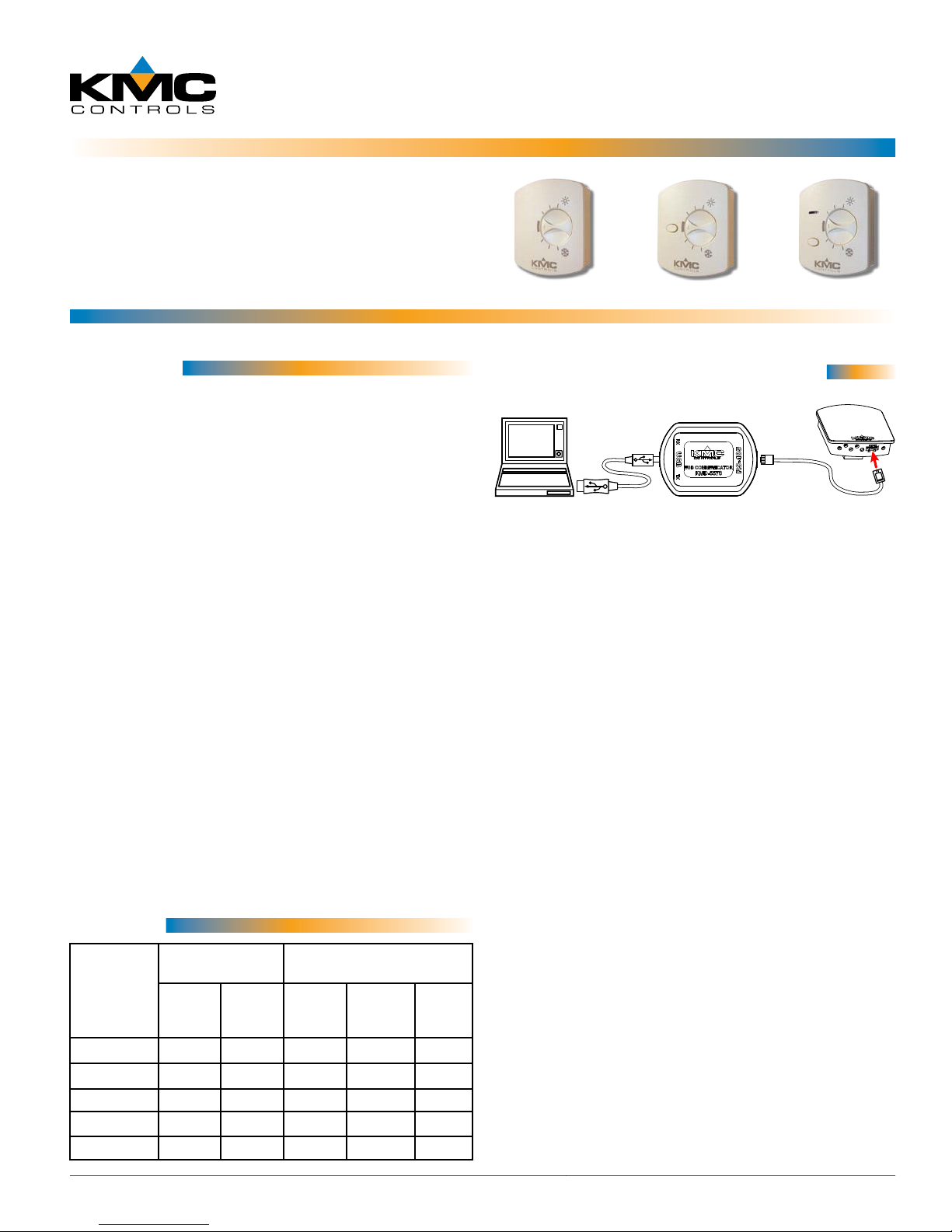
KMD-5624 PC Data Port (EIA-485) Cable
KMD-5576 EIA-485 to USB Communicator
SP-001 Flat Blade and Hex End Screw-
driver
© 2013 KMC Controls, Inc. AN0412B Rev. B
Specifications
Connections Clamp (screw-type) terminals
or modular RJ-45 jack (see
Models on page 1)
Material Flame-retardant plastic, light
almond or white
Weight Approx. 1.25 oz. (35 grams)
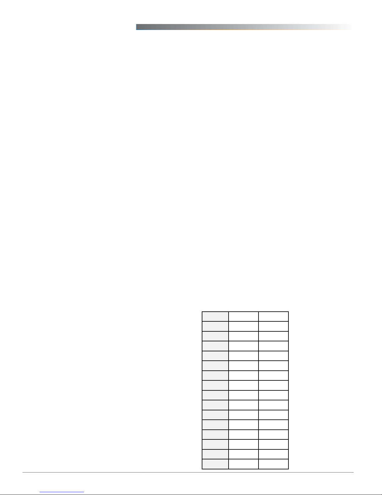
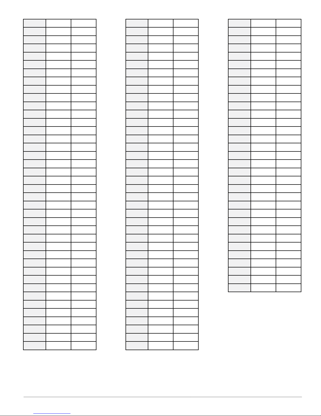
Sensor
Type Type II thermistor
Accuracy ± 0.36° F (± 0.20° C)
Resistance 10,000 ohms @ 77° F (25° C)
NTC 4.37%/° C @ 25° C
Dissipation Constant 2 mW/° C
Temp. Reading Thermistor resistance
Rotary Setpoint Pot. 0–10K ohms ±20% (54–90° F or
12–32° C) linear
Optional Buon One momentary push buon,
shunts temperature sensor to
signal override condition
Optional LED Power requirements, 10 VDC
(12 VDC max); 5 mA max. cur-
rent draw at 12 VDC
Environmental Limits
Operating 34° to 125° F (1.1° to 51.6° C)
Shipping –40° to 140° F (–40° to 60° C)
Humidity 0 to 95% RH non-condensing
Important Notices
The material in this document is for information
purposes only. The contents and the product it
describes are subject to change without notice.
KMC Controls, Inc. makes no representations or
warranties with respect to this document. In no event
shall KMC Controls, Inc. be liable for any damages,
direct or incidental, arising out of or related to the
use of this document.
Troubleshooting
• Be sure the 10,000 ohm pull-up resistors on the
controller board are turned ON.
• Check wiring. To prevent excessive voltage drop,
use a conductor size that is adequate for the
wiring length!
• Check sensor conguration and tables in the
controller.
• Check voltage from the controller.
• Check that the sensor is NOT mounted on an
exterior wall, mounted on or near a large ther-
mal mass, blocked from normal air circulation
by obstructions, exposed to heat sources or to
sunlight, exposed to drafts from windows or air
vents, or exposed to air ow through the conduit
from leaks in plenum ducts. (See the Mounting
Considerations section above.)
Mounting Considerations
Sensors must NOT be:
• Mounted on an exterior wall.
• Mounted on or near a large thermal mass (e.g.,
concrete block wall).
• Blocked from normal air circulation by obstruc-
tions.
• Exposed to heat sources (e.g., lights, computers,
copiers, or coee makers) or to sunlight (at any
time of the day).
• Exposed to drafts from windows, diusers, or
returns.
• Exposed to air ow through the conduit (from
leaks in plenum ducts)—put plumber’s puy or
similar material inside the conduit to block air
ow.
Other manuals for STE-6014
1
This manual suits for next models
4
Table of contents
Other KMC Controls Accessories manuals

KMC Controls
KMC Controls STE-6010-10 User manual

KMC Controls
KMC Controls Conquest STE-90 Series User manual

KMC Controls
KMC Controls STE-6010 User guide

KMC Controls
KMC Controls KMD-1183 Operating instructions

KMC Controls
KMC Controls STW Series User manual

KMC Controls
KMC Controls NetSensor KMD-1261 Operating instructions

KMC Controls
KMC Controls STE-1421 User manual

KMC Controls
KMC Controls THE-1105 User manual

KMC Controls
KMC Controls SSS-1000 Series User manual

KMC Controls
KMC Controls STE-6014 User manual