Blizzard 33980 User manual

May 15, 2008
Lit. No. 40388, Rev. 00
CAUTION
See your BLIZZARD®outlet/Web site for
specific vehicle application recommendations
before installation. The Undercarriage
Selection Guide has specific vehicle and
snowplow requirements.
CAUTION
Read this document before installing the
snowplow.
A DIVISION OF DOUGLAS DYNAMICS, L.L.C.
33980
UNDERCARRIAGE KIT
Dodge Ram W1500 1994 - 2001
Installation Instructions

Lit. No. 40388, Rev. 00 2 May 15, 2008
SAFETY DEFINITIONS
NOTE: Indicates a situation or action that can lead
to damage to your snowplow and vehicle or other
property. Other useful information can also be
described.
SAFETY
WARNING
Indicates a potentially hazardous situation
that, if not avoided, could result in death or
serious personal injury.
CAUTION
Indicates a potentially hazardous situation
that, if not avoided, may result in minor or
moderate injury. It may also be used to alert
against unsafe practices.
WARNING/CAUTION & INSTRUCTION LABELS
Become familiar with and inform users about the
warning and instruction labels on the back of the
blade.
NOTE: If labels are missing or cannot be read, see
your sales outlet.
Attach/Detach Instruction Label
Warning/Caution Label

Lit. No. 40388, Rev. 00 3 May 15, 2008
SAFETY PRECAUTIONS
Improper installation and operation could cause
personal injury, and/or equipment and property
damage. Read and understand labels and the Owner's
Manual before installing, operating or making
adjustments. PERSONAL SAFETY
• Remove ignition key and put the vehicle in park or
in gear to prevent others from starting the vehicle
during installation or service.
• Wear only snug-fitting clothing while working on
your vehicle or snowplow.
• Do not wear jewelry or a necktie, and secure long
hair.
• Wear safety goggles to protect your eyes from
battery acid, gasoline, dirt and dust.
• Avoid touching hot surfaces such as the engine,
radiator, hoses and exhaust pipes.
• Always have a fire extinguisher rated BC handy,
for flammable liquids and electrical fires.
SAFETY
WARNING
Lower blade when vehicle is parked.
Temperature changes could change hydraulic
pressure, causing the blade to drop
unexpectedly or damaging hydraulic
components. Failure to do this could result in
serious personal injury.
CAUTION
Refer to the Undercarriage Selection Guide for
minimum vehicle recommendations and
ballast requirements.
WARNING
Do not exceed GVWR or GAWR including the
blade and ballast. The rating label is found on
the driver-side vehicle door cornerpost.
WARNING
Remove blade assembly before placing vehicle
on hoist.
WARNING
The driver shall keep bystanders clear of the
blade when it is being raised, lowered or
angled. Do not stand between the vehicle and
the blade or within 8 feet of a moving blade. A
moving or falling blade could cause personal
injury.
WARNING
Keep hands and feet clear of the blade and
A-frame when mounting or dismounting the
snowplow. Moving or falling assemblies could
cause personal injury.
WARNING
To prevent accidental movement of the blade,
always turn the ON/OFF switch to OFF
whenever the snowplow is not is use. The
control indicator light will turn off.

Lit. No. 40388, Rev. 00 4 May 15, 2008
WARNING
Gasoline is highly flammable and gasoline
vapor is explosive. Never smoke while working
on vehicle. Keep all open flames away from
gasoline tank and lines. Wipe up any spilled
gasoline immediately.
WARNING
Vehicle exhaust contains lethal fumes.
Breathing these fumes, even in low
concentrations, can cause death. Never
operate a vehicle in an enclosed area without
venting exhaust to the outside.
FIRE AND EXPLOSION
Be careful when using gasoline. Do not use gasoline
to clean parts. Store only in approved containers away
from sources of heat or flame.
VENTILATION
CELL PHONES
A driver’s first responsibility is the safe operation of
the vehicle. The most important thing you can do to
prevent a crash is to avoid distractions and pay
attention to the road. Wait until it is safe to operate
Mobile Communication Equipment such as cell
phones or two-way radios.
SAFETY

Lit. No. 40388, Rev. 00 5 May 15, 2008
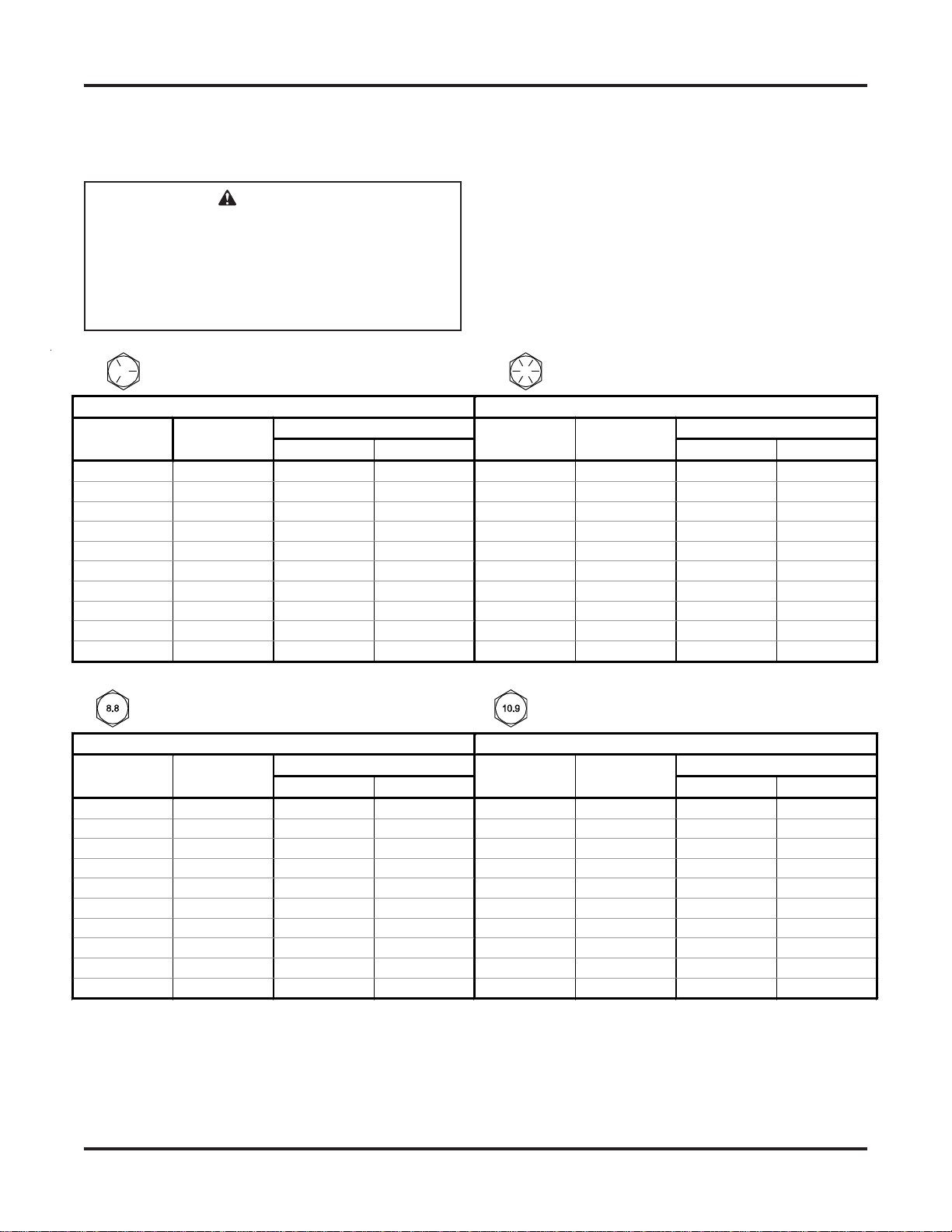
Grade Identification for J429–Grade 5 Bolt Grade Identification for J429–Grade 8 Bolt
SAE J429 Grade 5 Torque Values SAE J429 Grade 8 Torque Values
Tightening Torque Tightening Torque
Nominal
Thread Size Clamp Loads
(lb) "Lubricated" "Dry" Nominal
Thread Size Clamp Loads
(lb) "Lubricated" "Dry"
1/4-20 2,000 6 ft-lb 8 ft-lb 1/4-20 2,850 9 ft-lb 12 ft-lb
5/16-18 3,350 13 ft-lb 18 ft-lb 5/16-18 4,700 18 ft-lb 25 ft-lb
3/8-16 4,950 23 ft-lb 31 ft-lb 3/8-16 6,950 32 ft-lb 44 ft-lb
7/16-14 6,800 37 ft-lb 50 ft-lb 7/16-14 9,600 53 ft-lb 70 ft-lb
1/2-13 9,050 57 ft-lb 75 ft-lb 1/2-13 12,800 80 ft-lb 107 ft-lb
9/16-12 11,600 82 ft-lb 109 ft-lb 9/16-12 16,400 115 ft-lb 154 ft-lb
5/8-11 14,500 113 ft-lb 151 ft-lb 5/8-11 20,300 159 ft-lb 211 ft-lb
3/4-10 21,300 200 ft-lb 266 ft-lb 3/4-10 30,100 282 ft-lb 376 ft-lb
7/8-9 29,435 321 ft-lb 430 ft-lb 7/8-9 41,550 454 ft-lb 606 ft-lb
1-8 38,600 482 ft-lb 640 ft-lb 1-8 54,540 680 ft-lb 900 ft-lb
Grade Identification for Metric–Grade 8.8 Bolt Grade Identification for Metric–Grade 10.9 Bolt
Metric Class 8.8 Torque Values Metric Class 10.9 Torque Values
Tightening Torque Tightening Torque
Diameter
(mm) Clamp Loads
(lb) "Lubricated" "Dry" Diameter
(mm) Clamp Loads
(lb) "Lubricated" "Dry"
5 1,389 3 ft-lb 5 ft-lb 5 1,987 5 ft-lb 7 ft-lb
6 1,965 6 ft-lb 8 ft-lb 6 2,812 8 ft-lb 11 ft-lb
7 2,826 10 ft-lb 13 ft-lb 7 4,044 14 ft-lb 19 ft-lb
8 3,579 14 ft-lb 19 ft-lb 8 5,121 20 ft-lb 27 ft-lb
10 5,672 28 ft-lb 37 ft-lb 10 8,116 40 ft-lb 53 ft-lb
12 8,243 49 ft-lb 65 ft-lb 12 11,796 70 ft-lb 92 ft-lb
14 11,246 77 ft-lb 103 ft-lb 14 16,092 111 ft-lb 148 ft-lb
16 15,882 125 ft-lb 167 ft-lb 16 21,970 173 ft-lb 231 ft-lb
18 19,423 172 ft-lb 229 ft-lb 18 26,868 238 ft-lb 317 ft-lb
20 24,784 244 ft-lb 325 ft-lb 20 34,284 338 ft-lb 450 ft-lb
TORQUE SPECIFICATIONS
CAUTION
Read instructions before assembling.
Fasteners should be finger tight until
instructed to tighten according to the torque
chart. Use standard methods and practices
when attaching snowplow including proper
personal protective safety equipment.
TORQUE CHART

Lit. No. 40388, Rev. 00 6 May 15, 2008
UNDERCARRIAGE INSTALLATION
INSTALLATION INSTRUCTIONS
NOTE: For easier assembly and installation,
vehicle and all snowplow components should be
on a smooth, level, hard surface, such as concrete.
1. Remove the frame brackets from the sway bar
and discard the fasteners. Inspect the two forward
bumper bracket bolt-on clips. They must point out
from the vehicle centerline. If they are pointing
toward the centerline, remove and reinstall in the
proper orientation by loosely fastening the top nut
only (see illustration).
3. Insert a 1/2" x 1-1/4" cap screw with handle and
1/2" washer through the square hole in the frame
located just behind the frame cross member. Pass
the cap screw through slot in frame and the larger
of the three holes in the mount. Care must be
taken to ensure the washer does not fall off
cap screw during this operation.
4. Loosely fasten with a 1/2" washer and
1/2" locknut. Loosely reinstall the single bumper
bracket fastener through appropriate hole in the
mount.
If the bolt-on clips are pointing out from centerline,
remove the lower nut and loosen the upper.
Remove and save the remaining bumper bracket
fastener located to the rear of the bolt-on clip
fasteners. On 1500 model trucks the ground wire
tap screw interferes with the driver-side mount.
Remove and relocate the tap screw.
2. Hang the driver-side mount by the hole in the front
of the hanger on the lower bolt in the front bumper
bracket. Loosely secure with original nut. Do not
tighten any fasteners until instructed to do so.
Swing the mount into place.
Reuse bumper
bracket bolt-on clips
on both sides.
Reuse bumper bracket
fasteners on both sides.
1994 to 1996 – top hole
1997 to present – bottom hole
1/2" x 1-1/4"
Cap Screw
with Handle
Bumper Bracket
Fasteners
1/2" Washer
and Locknut

Lit. No. 40388, Rev. 00 7 May 15, 2008
6. Repeat steps 2, 3, 4 and 5 for the passenger-side
mount. Insert a 1/2" x 1-1/4" cap screw with
handle in through the square hole with the bumper
brace attached and out through frame and top
hole on mount. Fasten with 1/2" locknut.
7. Reattach the sway bar brackets to the mounts and
frame with four M10 x 1.5 x 40 cap screws, flat
washers and lock washers.
(Viewed from the back)
5. Install a 7/16" x 1-1/4" cap screw with flat washer
through slot in mount and frame cross member.
Place a 7/16" washer between the mount and
cross member. Loosely fasten 7/16" flat washer
and locknut. Do not tighten any fasteners until
instructed to do so.
Washer
7/16" x 1-1/4" Cap Screw,
Washer and Locknut
M10 x 1.5 x 40
Cap Screw
and Washers
Driver-Side
Receiver
U-Bracket
UNDERCARRIAGE INSTALLATION
8. Tighten the sway bar bolts first and then all
remaining fasteners. Tighten all fasteners per
torque chart. Bend or trim the handles on all cap
screws with handles to prevent contact with any
vehicle components.

Lit. No. 40388, Rev. 00 8 May 15, 2008
MOUNT ADAPTER INSTALLATION
MOUNT ADAPTER MEASUREMENT
With vehicle on level ground, measure from ground to
center of the hole on U-bracket sideplate on mount.
The recommended height of the mount should be
14-1/4" or less from the center of the U-bracket hole
to level ground. If the mount is higher than 14-1/4",
the enclosed adapter plates need to be attached to
the Mount Adapter. (The Mount Adapter comes
packaged with the Blade Crate Assembly.)
If measured height is 14-1/4" or less, no height
adjustment is needed.
If measured height is 14-1/4" – 15-3/4", install the
short height adjustment adapter plates as described.
MOUNT ADAPTER INSTALLATION
If adapter plates are required, install as follows:
1. Position the adapter plate against the driver’s
side portion of the mount adapter as shown. Insert
a 3/4" x 2-3/4" cap screw through the lower front
adapter plate hole and through the appropriate
hole on the mount adapter. Secure with a locknut.
2. Insert a cap screw through the rear adapter plate
hole, through the slot on the mount adapter and
through a washer. Secure with a locknut.
3. Repeat for the passenger’s side. Torque all four
fasteners according to torque chart on page 4.
Center
of Hole Mount
Mount
A
dapter 14-1/4"or less
Adapter
Plate
Mount
Center
of Hole
Mount
A
dapter
14-1/4" – 15-3/4"
Mount Adapter
Adapter
Plate
NOTE: After five to ten hours of snowplow usage,
retorque all mount assembly fasteners.

Lit. No. 40388, Rev. 00 9 May 15, 2008

Lit. No. 40388, Rev. 00 10 May 15, 2008
Blizzard reserves the right under its product improvement policy to change construction or design details and furnish equipment when so altered
without reference to illustrations or specifications used. Blizzard or the vehicle manufacturer may require or recommend optional equipment for
snowremoval.Donotexceedvehicleratingswithasnowplow.Blizzardoffersalimitedwarrantyforallsnowplowsandaccessories.Seeseparately
printed page for this important information. The following is a registered (®) trademark of Douglas Dynamics, L.L.C.: BLIZZARD®.
Printed in U.S.A.
A DIVISION OF DOUGLAS DYNAMICS, L.L.C.
Blizzard
P.O. Box 245038
Milwaukee, WI 53224-9538
www.blizzardplows.com
Table of contents
Other Blizzard Automobile Accessories manuals
Popular Automobile Accessories manuals by other brands

Connects2
Connects2 CT51-BM06 installation guide

STO N SHO
STO N SHO SNS 238 Installation procedures

Aervoe
Aervoe 1160 Amber LEDs operating instructions

Metra Electronics
Metra Electronics 99-6507 installation instructions

Thule
Thule Rapid System 1055 instructions

GATmatic
GATmatic TWC902 Installation, operation & maintenance manual