Blizzard 680LT Service manual

Models 680LT & 720LT
Installation Instructions & Owner's Manual
March 1, 2009
Lit. No. B64118, Rev. 03
This manual supersedes all editions with an earlier date.
CAUTION
Read this document before operating or
servicing snowplow.
CAUTION
Read this document before installing the
snowplow.
CAUTION
See your BLIZZARD sales outlet/Web site for
specific vehicle application recommendations
before installation. The Undercarriage
Selection Guide has specific vehicle and
snowplow requirements.

Lit. No. B64118, Rev. 03 2 March 1, 2009
PREFACE
Congratulations on purchasing the finest straight
blade snowplow available! BLIZZARD®straight
blades are clearing new trails for innovative design,
rugged durability, quality craftsmanship and superior
performance. Our innovative products are tested all
over the snowbelt.
This manual provides safety, operation and
maintenance information for your new BLIZZARD
snowplow. To keep your snowplow in good condition,
read and understand this manual and follow its
recommendations. Failure to do so may affect your
warranty coverage.
When service is necessary, your local BLIZZARD
distributor knows your snowplow best. Contact your
BLIZZARD outlet for maintenance, service or any
other assistance you may require.
If you have not already done so, please visit
www.blizzardplows.com to register your new
BLIZZARD snowplow!

Lit. No. B64118, Rev. 03 3 March 1, 2009
Preface ........................................................................ 2
Safety Information ....................................................... 4
Vehicle Application Information................................... 7
Operation..................................................................... 8
Unpacking & Inspection .............................................. 9
Torque Specifications ................................................ 10
Moldboard & A-Frame Assembly .............................. 12
Electrical & Hydraulic Systems.................................. 16
Manifold Assembly &
Electrical Installation – Snowplow Side ....... 16
General System Schematics .............................. 18
Hydraulic Guide .................................................. 19
Electrical Schematics – Snowplow Side............. 20
Electrical Installation – Vehicle Side ................... 23
Electrical Schematics – Vehicle Side .................26
TABLE OF CONTENTS
POWER HITCH™ System Instructions.....................30
Testing Your Snowplow ............................................. 31
Headlamp Aiming ...................................................... 33
Maintenance..............................................................34
Technical Specifications............................................ 35
Troubleshooting......................................................... 36
Parts Lists.................................................................. 38
Moldboard Parts – All Models............................. 38
A-Frame & Pivot Beam Parts – All Models......... 40
Power Unit Parts – All Models ............................ 42
Lights & Control Parts – All Models ....................44
Accessories & Kits – All Models .........................46

Lit. No. B64118, Rev. 03 4 March 1, 2009
SAFETY DEFINITIONS
NOTE: Indicates a situation or action that can lead
to damage to your snowplow and vehicle or other
property. Other useful information can also be
described.
WARNING/CAUTION & INSTRUCTION
LABELS
Become familiar with and inform users about the
warning and instruction labels on the back of the
blade.
NOTE: If labels are missing or cannot be read, see
your sales outlet.
SAFETY
WARNING
Indicates a potentially hazardous situation,
that if not avoided, could result in death or
serious personal injury.
CAUTION
Indicates a potentially hazardous situation
that, if not avoided, may result in minor or
moderate injury. It may also be used to alert
against unsafe practices.
Crush
Crush
hazard.
hazard.
Keep feet
Keep feet
clear.
clear.
WARNING
WARNING
•
Kickstand must be lowered, with kickstand pin seated in lower hole on pivot beam.
• Slowly drive vehicle forward until pushbeam receiver mount points contact
A-frame mount bushings.
• Turn POWER HITCH OPERATION switch (on plow control) to "ON" position.
• Connect plow and vehicle electrical harnesses. Connect weather caps together.
•
Raise plow. Lower kickstand until kickstand pin is seated in lower hole on pivot beam.
• Lower plow on flat, level surface. Turn vehicle ignition off.
• Remove hitch pins from A-frame and undercarriage.
• Turn vehicle ignition on.
• Turn POWER HITCH OPERATION switch (on plow control) to "ON" position.
• Pull A-frame latch lock pin out and lower A-frame latch over draw pin.
• Push and hold CONNECT/DISCONNECT switch upward. POWER HITCH arm
will engage back of pushbeam and pull plow into pushbeam receiver mount
points on vehicle.
• Insert both hitch pins and secure each with hair pin cotter.
• Lower POWER HITCH arm to relieve tension on A-frame latch. Raise A-frame
latch and lock into position with lock pin. Raise plow.
• Raise kickstand until kickstand pin seats into upper hole on pivot beam.
• Push and hold CONNECT/DISCONNECT switch downward. POWER HITCH
arm will disengage from behind undercarriage pushbeam and lower.
• Disconnect plow and vehicle electrical harnesses. Install weather caps.
• Turn SYSTEM POWER (on plow control) to "OFF" position.
• Slowly move vehicle backward away from plow.
MOUNT INSTRUCTIONS DISMOUNT INSTRUCTIONS
Read Owner's Manual for Complete Instructions. Read Owner's Manual for Complete Instructions.
WARNING: Keep fingers away from plow and truck mounting points.
WARNING: Keep fingers away. POWER HITCH arm raises behind undercarriage pushbeam.
A-Frame
Latch Hitch
Pin
A-Frame
Latch
Lock Pin
Draw
Pin
A-Frame Latch
rotates clockwise
and hooks onto
Draw Pin
CONNECT/DISCONNECT
POWER HITCH Switch
Adjustable
Kickstand
Adjustable
Kickstand
A-Frame
Mount Bushing
Pushbeam
Receiver
Mount Points
POWER
HITCH Arm
Slowly Move
Vehicle Forward
Slowly
Move Vehicle
Backward
Undercarriage
Pushbeam
CONNECT/DISCONNECT
POWER HITCH Switch
CONNECT/DISCONNECT
POWER HITCH Switch
POWER
HITCH Arm
POWER HITCH Arm
Hitch
Pin
Kickstand Pin
Kickstand Pin
Adjustable
Kickstand
Kickstand Pin
STEP #1 STEP #1
STEP #2 STEP #2
44812
U.S. Patents 5,638,618; 5,899,007; 6,178,669; 6,276,076; 6,393,737; 6,408,549; 6,412,199; 6,442,877; 6,615,513; Canadian and other patents pending.

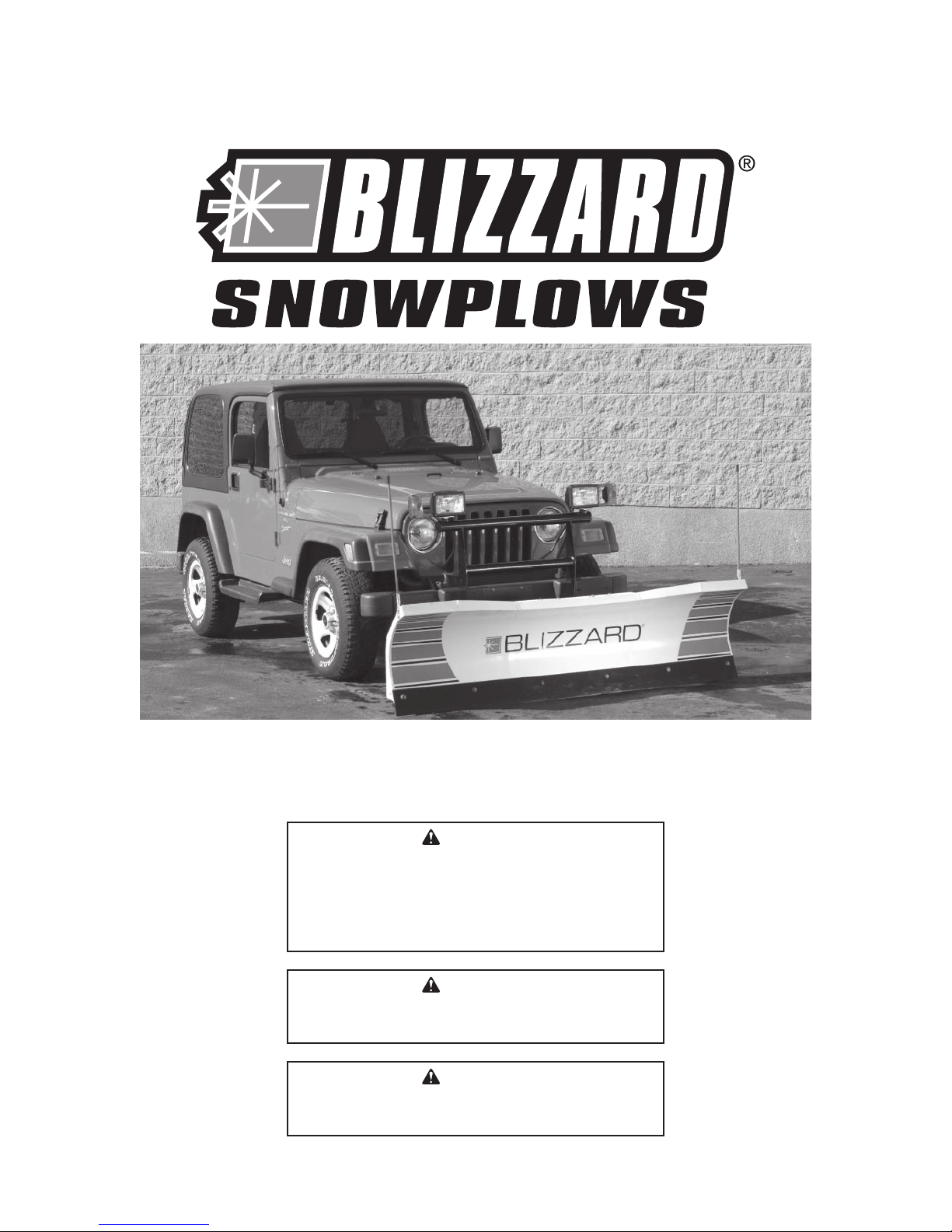
Lit. No. B64118, Rev. 03 5 March 1, 2009
SAFETY PRECAUTIONS
Improper installation and operation could cause
personal injury, and/or equipment and property
damage. Read and understand labels and the
Owner's Manual before installing, operating or making
adjustments.
HYDRAULIC SAFETY
Always inspect hydraulic components and hoses•
before using. Replace any damaged or worn parts
immediately.
If you suspect a hose leak, DO NOT use your•
hand to locate it. Use a piece of cardboard or
wood.
FUSES
The snowplow electrical and hydraulic systems
contain several blade-style automotive fuses. If
a problem should occur and fuse replacement is
necessary, the replacement fuse must be of the same
type and amperage rating as the original. Installing a
fuse with a higher rating can damage the system and
could start a fire. Fuse Replacement, including fuse
ratings and locations, is located in the Maintenance
Section of this Owner's Manual.
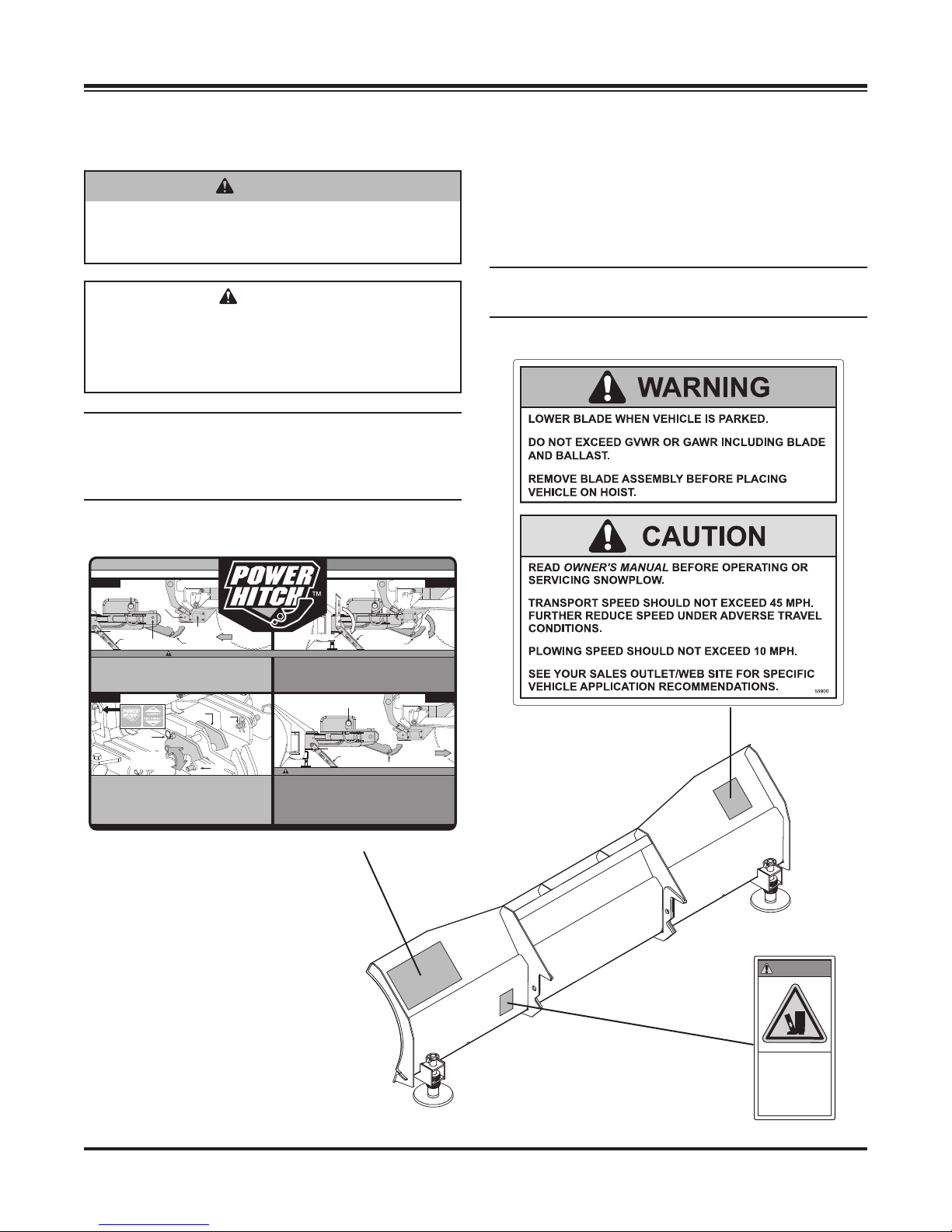
SAFETY
WARNING
Lower blade when vehicle is parked.
Temperature changes could change
hydraulic pressure, causing the blade to
drop unexpectedly or damaging hydraulic
components. Failure to do this could result in
serious personal injury. CAUTION
See your BLIZZARD®outlet for application
recommendations.
CAUTION
Plowing speed should not exceed 10 mph.
CAUTION
Transport speed should not exceed 45 mph.
Further reduce speed under adverse travel
conditions.
CAUTION
Read Owner's Manual before operating or
servicing snowplow.
WARNING
Do not exceed GVWR or GAWR including the
blade and ballast. The rating label is found on
the driver-side vehicle door cornerpost.
WARNING
Remove blade assembly before placing
vehicle on hoist.
WARNING
The driver shall keep bystanders clear of
the blade when it is being raised, lowered or
angled. Do not stand between the vehicle and
the blade or within 8 feet of a moving blade. A
moving or falling blade could cause personal
injury.
WARNING
You can die or be seriously injured. Keep
hands and feet away from hitch mechanism
and snowplow blade when operating the
POWER HITCH™ arm. The action of the arm
moves the snowplow toward the vehicle and
into position for proper attachment.
WARNING
To prevent accidental movement of the
blade, always turn the ON/OFF switch to OFF
whenever the snowplow is not in use. The
control indicator light (touchpad only) will
turn off.
WARNING
Hydraulic fluid under pressure can cause skin
injection injury. If you are injured by hydraulic
fluid, get medical attention immediately.

Lit. No. B64118, Rev. 03 6 March 1, 2009
PERSONAL SAFETY
Remove ignition key and put the vehicle in park or•
in gear to prevent others from starting the vehicle
during installation or service.
Wear only snug-fitting clothing while working on•
your vehicle or snowplow.
Do not wear jewelry or a necktie, and secure long•
hair.
Wear safety goggles to protect your eyes from•
battery acid, gasoline, dirt and dust.
Avoid touching hot surfaces such as the engine,•
radiator, hoses and exhaust pipes.
Always have a fire extinguisher rated BC handy,•
for flammable liquids and electrical fires.
FIRE AND EXPLOSION
Be careful when using gasoline. Do not use gasoline
to clean parts. Store only in approved containers away
from sources of heat or flame.
CELL PHONES
A driver's first responsibility is the safe operation of
the vehicle. The most important thing you can do
to prevent a crash is to avoid distractions and pay
attention to the road. Wait until it is safe to operate
Mobile Communication equipment such as cell phones
or two-way radios.
VENTILATION
BATTERY SAFETY
NOISE
Airborne noise emission during use is below 70 dB(A)
for the snowplow operator.
SAFETY
CAUTION
Batteries normally produce explosive gases
which can cause personal injury. Therefore,
do not allow flames, sparks or lit tobacco
to come near the battery. When charging or
working near a battery, always cover your
face and protect your eyes, and also provide
ventilation.
Batteries contain sulfuric acid which burns
skin, eyes and clothing.
Disconnect the battery before removing or
replacing any electrical components.
WARNING
Vehicle exhaust contains lethal fumes.
Breathing these fumes, even in low
concentrations, can cause death. Never
operate a vehicle in an enclosed area without
venting exhaust to the outside.
WARNING
Gasoline is highly flammable and gasoline
vapor is explosive. Never smoke while
working on vehicle. Keep all open flames
away from gasoline tank and lines. Wipe up
any spilled gasoline immediately.

Lit. No. B64118, Rev. 03 7 March 1, 2009
VEHICLE APPLICATION INFORMATION
Vehicle application recommendations are based on
the following:
The vehicle with the snowplow installed must•
comply with applicable Federal Motor Vehicle
Safety Standards (FMVSS).
The vehicle with the snowplow installed must•
comply with the vehicle manufacturer's stated
gross vehicle and axle weight ratings (found on
the driver-side door cornerpost of the vehicle) and
the front and rear weight distribution ratio. In some
cases, rear ballast may be required to comply with
these requirements.
BLIZZARD Undercarriage Selection Guide is•
based on available vehicle capacity for snowplow
equipment on a representative vehicle equipped
with options commonly used for plowing and with
300 lb of front seat occupant weight.
Weights of front seat occupants can be adjusted•
above 300 lb but vehicle with snowplow must not
exceed vehicle GVWR or GAWR.
In some cases there may be additional limitations•
and requirements.
Installation, modification and addition of•
accessories must comply with published
BLIZZARD recommendations and instructions.
Available capacity decreases as the vehicle is
loaded with cargo or other truck equipment or
snowplow accessories are installed.
If there is uncertainty as to whether available•
capacity exists, the actual vehicle as configured
must be weighed.
CAUTION
See your BLIZZARD®outlet for specific
vehicle application recommendations before
installation. The Undercarriage Selection
Guide has specific vehicle and snowplow
requirements.
BALLAST REQUIREMENTS
Ballast (additional weight) is an important part of
qualifying vehicles for snowplow eligibility. Rear
ballast must be used when necessary to remain in
compliance with axle ratings and ratios as specified by
the vehicle manufacturer.
If ballast is required, it is important that it be secured
properly behind the rear axle. A ballast retainer kit is
available from your BLIZZARD outlet, PN 62849.
NOTE: The ballast retainer kit is for snowplow
vehicles requiring ballast. See your BLIZZARD
outlet for the correct amount of ballast required.
Include the weight of the retainer as part of the
ballast requirement. Sand bags are recommended
for use as ballast.
NOTE: Ballast recommended and its weight
calculations assume the entire width of the bed is
filled as close to tailgate as possible.
Position
and secure ballast
as close to the tailgate
as possible.

Lit. No. B64118, Rev. 03 8 March 1, 2009
OPERATION
Your snowplow is the most advanced and versatile
straight blade on the market. The easy-to-use controls
allow you to automatically adjust the snowplow blade
into an infinite number of plowing positions. Review
the illustrations below for instruction on maneuvering
your snowplow.
A. Lowered or Float Position
Pushing the joystick forward, toward the
"Lower/Float" designation on the label, or
pushing the D button on the touchpad will lower
your straight blade to the ground. Pushing and
momentarily holding the control in this position will
allow the snowplow to "float," or follow the contour
of the ground when moving forward or backward.
B. Raised Position
Pulling the joystick back, toward the "Raise"
designation on the label, or pushing the U button
on the touchpad will lift your straight blade off
the ground. To stop raising the snowplow, simply
return the joystick to its "neutral" or center position
or release the touchpad button. The snowplow has
reached its maximum raised position when the
blade stops lifting.
C. Angled Right Position
To angle your straight blade to the right, position
the joystick toward the "R" on the label or push
the R button on the touchpad. To stop angling the
snowplow, return the joystick to its "neutral" or
center position or release the touchpad button.
The snowplow has reached its maximum angled
position when the blade stops moving to the right
side.
D. Angled Left Position
To angle your straight blade to the left, position
the joystick toward the "L" on the label or push
the L button on the touchpad. To stop angling the
snowplow, return the joystick to its "neutral" or
center position or release the touchpad button.
The snowplow has reached its maximum angled
position when the blade stops moving to the left
side.
NOTE: To prevent premature failure of the power
contactor (solenoid), return the joystick to its
neutral (center) position or release the touchpad
button immediately after the blade reaches the
limit of any position. Continuing to hold the
control after the blade has reached the limit of
movement in any position will reduce the life of
the solenoid.
A.
B.
D.
C.

Lit. No. B64118, Rev. 03 9 March 1, 2009
UNPACKING & INSPECTION
Your BLIZZARD®straight blade has been packaged
to withstand transit and weather related damage.
Fully inspect all components upon receipt of your
snowplow. In the event of shipping damage or missing
parts, immediately contact our Customer Service
Department at 1-888-680-8600.
Begin unpacking and inspection in the following order:
1. Remove the shipping document from the end
panel of the pallet wrap. Retain all documentation
for your records.
2. All wood framing and polyethylene material should
be removed from the pallet for easy access to the
snowplow.
3. Due to the odd shaped components and size
of several assembly parts, various cable ties
and corrugated material are used for scratch
resistance and package orientation. Please
remove these items prior to assembly.
4. Place the main blade assembly on a flat, level
surface.
Once you have inspected all parts and removed all
packaging materials, your snowplow is ready to be
fully assembled.
Retain this information for your records.
Date of Purchase:
Dealer/Distributor:
Dealer Phone Number:
Snowplow Serial Number:
Hydraulic Pump Serial Number:

Lit. No. B64118, Rev. 03 10 March 1, 2009
TORQUE SPECIFICATIONS
TORQUE CHART
CAUTION
Read instructions before assembling.
Fasteners should be finger tight until
instructed to tighten according to the torque
chart. Use standard methods and practices
when attaching snowplow including proper
personal protective safety equipment.
Grade Identification for J429–Grade 5 Bolt Grade Identification for J429–Grade 8 Bolt
SAE J429 Grade 5 Torque Values SAE J429 Grade 8 Torque Values
Nominal
Thread Size
Clamp Loads
(lb)
Tightening Torque Nominal
Thread Size
Clamp Loads
(lb)
Tightening Torque
"Lubricated" "Dry" "Lubricated" "Dry"
1/4-20 2,000 6 ft-lb 8 ft-lb 1/4-20 2,850 9 ft-lb 12 ft-lb
5/16-18 3,350 13 ft-lb 18 ft-lb 5/16-18 4,700 18 ft-lb 25 ft-lb
3/8-16 4,950 23 ft-lb 31 ft-lb 3/8-16 6,950 32 ft-lb 44 ft-lb
7/16-14 6,800 37 ft-lb 50 ft-lb 7/16-14 9,600 53 ft-lb 70 ft-lb
1/2-13 9,050 57 ft-lb 75 ft-lb 1/2-13 12,800 80 ft-lb 107 ft-lb
9/16-12 11,600 82 ft-lb 109 ft-lb 9/16-12 16,400 115 ft-lb 154 ft-lb
5/8-11 14,500 113 ft-lb 151 ft-lb 5/8-11 20,300 159 ft-lb 211 ft-lb
3/4-10 21,300 200 ft-lb 266 ft-lb 3/4-10 30,100 282 ft-lb 376 ft-lb
7/8-9 29,435 321 ft-lb 430 ft-lb 7/8-9 41,550 454 ft-lb 606 ft-lb
1-8 38,600 482 ft-lb 640 ft-lb 1-8 54,540 680 ft-lb 900 ft-lb
8.8 Grade Identification for Metric–Grade 8.8 Bolt 10.9 Grade Identification for Metric–Grade 10.9 Bolt
Metric Class 8.8 Torque Values Metric Class 10.9 Torque Values
Diameter
(mm)
Clamp Loads
(lb)
Tightening Torque Diameter
(mm)
Clamp Loads
(lb)
Tightening Torque
"Lubricated" "Dry" "Lubricated" "Dry"
5 1,389 3 ft-lb 5 ft-lb 5 1,987 5 ft-lb 7 ft-lb
6 1,965 6 ft-lb 8 ft-lb 6 2,812 8 ft-lb 11 ft-lb
7 2,826 10 ft-lb 13 ft-lb 7 4,044 14 ft-lb 19 ft-lb
8 3,579 14 ft-lb 19 ft-lb 8 5,121 20 ft-lb 27 ft-lb
10 5,672 28 ft-lb 37 ft-lb 10 8,116 40 ft-lb 53 ft-lb
12 8,243 49 ft-lb 65 ft-lb 12 11,796 70 ft-lb 92 ft-lb
14 11,246 77 ft-lb 103 ft-lb 14 16,092 111 ft-lb 148 ft-lb
16 15,882 125 ft-lb 167 ft-lb 16 21,970 173 ft-lb 231 ft-lb
18 19,423 172 ft-lb 229 ft-lb 18 26,868 238 ft-lb 317 ft-lb
20 24,784 244 ft-lb 325 ft-lb 20 34,284 338 ft-lb 450 ft-lb

Lit. No. B64118, Rev. 03 11 March 1, 2009
TORQUE SPECIFICATIONS
37° JIC Flare Torque Values
Turns Size ft-lb
min–max Assembly Steps
N/A -02 6–7 1. Make sure the tubing and threads are clean.
2. Lubricate the threads with 10W hydraulic fluid.
3. Hand tighten the nut/sleeve to approximately 30 in-lb.
4. Make alignment marks on the nut and fitting.
5. Tighten to turn or torque specification.
6. When fully tightened, make a second set of alignment marks at the fully tightened position.
NOTE: Torque values specified are for threads lubricated with 10W hydraulic fluid.
Overtightening will reduce the clamping force resulting in loss of seal and reduction of flow.
N/A -03 8–9
2-0411–12
2-0514–15
1-1/2 -06 18–20
1-1/2 -08 36–39
1-1/2 -10 57–63
1-1/4 -12 79–88
1-1494–103
1-16108–113
1-20127–133
1-24158–167
1-32245–258
O-Ring Boss Torque Values
Size ft-lb
min–max Assembly Steps
-02 6–7 1. Verify the port, O-ring, sealing surfaces and threads are clean and free of damage.
2. Lubricate the threads and the O-ring with 10W hydraulic fluid.
3. For an adjustable ORB, completely back off the locknut and washer.
4. Hand tighten the fitting until it contacts the port spotface. Point the elbow or tee in the desired
direction and hold.
5. Torque to specification.
NOTE: Torque values specified are for threads lubricated with 10W hydraulic fluid.
-03 8–10
-04 13–15
-05 17–21
-06 22–25
-08 40–43
-10 43–57
-12 68–75
-14 90 –99
-16 112–123
-20 146–200
-24 154–215
-32 218–290

Lit. No. B64118, Rev. 03 12 March 1, 2009
MOLDBOARD & A-FRAME ASSEMBLY
1/8" Ground
Clearance
Spring Loaded
Adjustable
Pivot Beam
Kickstand
1. Position the pivot beam and A-frame near
the connecting points at the rear of the blade
between the two center support ribs. Insert one
3/4" x 3-7/16" clevis pin through each mounting
hole and secure with 1/4" x 1-1/2" cotter pin.
2. Mount the kickstand to the end of the pivot beam
(driver's side) using the 1/2" x 4-1/2" bolt provided.
The spring, bushing and locknut are located on
the inside of the pivot beam. Review the diagrams
below and to the right. To pivot the kickstand, pull
the spring loaded leg out and rotate it until the pin
locks into place. Adjust the foot on the stand arm
so that the foot is 1/8" from the ground when the
A-frame is level and the A-frame mount points
are 10-1/2" from the ground. Tighten both of the
locknuts on the kickstand.
10-1/2"

Lit. No. B64118, Rev. 03 13 March 1, 2009
MOLDBOARD & A-FRAME ASSEMBLY
3. Hook each extension spring to the receiving holes
on the pivot beam and attach the opposite end of
the spring to its respective spade bolts. Install the
spade bolts through the extension spring mounting
angle on the top rear of the blade. Secure each
spade bolt by placing one 5/8" flat washer on the
bolt and thread one 5/8" locknut. Tighten each
locknut until a piece of paper can pass between
the 3rd and 4th coils on the spring.
4. Install the blade guides at each end of the
moldboard. Insert the cap screw through the holes
at the top of the wing reinforcement rib. Tighten all
screws with locknuts.

Lit. No. B64118, Rev. 03 14 March 1, 2009
MOLDBOARD & A-FRAME ASSEMBLY
7. Remove the plastic dust caps from the hydraulic
lift cylinder ports. Attach one 7/16" 90° adjustable
elbow ORB adapter to the extend port (base end)
and one 7/16" male ORB connector adapter to
the retract port (rod end). Connect the straight
end of the 1/4" x 13-1/2" hydraulic hose (B60432)
to the rod end adapter. Tighten fittings and hose
according to the torque chart.
8. Position the lift cylinder in the channel opening
under the A-frame. Route the 13-1/2" rod end
hose through the front (closest to the pivot beam)
2" diameter hole in the A-frame. The lift cylinder
base end hole should be aligned with the holes on
either side of the channel. Secure the lift cylinder
to the A-frame using a 5/8" x 5-3/4" clevis pin and
one 1/4" x 1-1/2" cotter pin. Use the access hole in
the A-frame, located on the driver's side, to install
the clevis pin. Connect the 1/4" x 10" hydraulic
hose (B60293) to the base end adapter. Tighten
hose according to the torque chart.
5. Remove the dust cap from both of the hydraulic
angle cylinder ports and attach one 7/16" male
ORB adapter to each port. Connect the straight
end of one 1/4" x 25" hydraulic hose (B60426)
to each angle cylinder adapter. Be careful not to
overtighten the hose connections. Route both
hoses through the A-frame access holes, near the
angle cylinder mount brackets. Tighten fittings and
hoses according to the torque chart.
6. Position each angle cylinder with the rod
end of the cylinder in the pivot beam. Secure
the cylinders to the pivot beam with a
3/4" x 3-7/16" clevis pin and a 1/4" x 1-1/2" cotter
pin. Extend each cylinder rod until the cylinder
base mounting hole aligns with the hole on the
A-frame angle cylinder bracket. Insert another
clevis pin and secure it with a cotter pin.
B60003
- Manifold Ports #1, 2 & 4
B60287
- Manifold Port #3
B60008
- Lift Cylinder Base End
B60004
- Lift Cylinder Rod End
- Angle Cylinders
9/16
7/16
7/16
7/16
7/16
7/16
7/16
9/16

Lit. No. B64118, Rev. 03 15 March 1, 2009
MOLDBOARD & A-FRAME ASSEMBLY
9. Remove the draw latch mount pin, spacer and
cotter pin from the draw latch assembly. By
removing this pin, the inner draw latch plates can
swing free. Remove the inner draw latch plate lift
cylinder mount pin. Position the plates on either
side of the lift/lower cylinder rod and insert the
pin through the plates and cylinder rod. With the
cylinder connected to the inner draw latch plates,
rotate the draw latch assembly toward the draw
latch mount holes on the A-frame. Align the holes
in the outer draw latch plate with those of the inner
draw latch plates and the A-frame.
NOTE: The A-frame latch, located at the
rear/center of the A-frame, should be raised
up to insert the draw latch mount pin. Pull the
A-frame latch pull pin out and rotate the latch
counterclockwise if it is locked into position.
Secure the assembly to the A-frame by replacing
the draw latch mount pin, spacer and cotter pin.
Reset the A-frame latch so the A-frame latch pull
pin locks into place.
A-Frame
Lock Pin
A-Frame
Latch
3/16" x 2-1/2"
Cotter Pin
Hydraulic
Lift/Lower
Cylinder
1" x 3-1/4"
Draw Latch
Mount Pin
5/8" x 2-1/16"
Inner Draw Latch Plate
Lift Cylinder Mount Pin
1" x 4-1/2"
Draw Pin
Draw Latch Arm
Pivot Pin
3/4" x 2-1/16"
1/4" x 1-1/2"
Cotter Pin
3/4"-10
Locknut
3/4" x 3-7/16"
Clevis Pin
3/4" x 3-1/2"
Cap Screw
Inner Draw Latch Plate
Outer Draw Latch Plate

Lit. No. B64118, Rev. 03 16 March 1, 2009
NOTE: The snowplow side electrical harness and
connect/disconnect switch must be installed
before the manifold is secured.
1. Remove the nut, washer and alignment ring
from the POWER HITCH™ connect/disconnect
toggle switch and insert it through the back of
the mounting bracket on the A-frame. Align the
notches on the switch and bracket. Replace the
alignment ring, washer and nut and tighten until
the switch is firmly in place. Attach the connector
on the snowplow harness to the switch.
NOTE: Use caution when connecting, switches
can break if done forcefully.
2. Attach the connector on the harness to the
connector on the coil harness.
3. Assemble the manifold. The manifold, pump
and coil harness have been connected at the
factory; however, the manifold contains several
components that you will need to install prior to
securing the assembly to the A-frame. Each of the
hose ports on the manifold is covered with a dust
cap. Remove the cap and install the appropriate
fitting in its respective port. Tighten fittings and
hoses according to the torque chart. Rest the
manifold assembly between the mount brackets
on the A-frame.
NOTE: The arrow shown on the manifold
illustration indicates the direction the
90° adapters should be positioned to receive the
hydraulic hoses.
MANIFOLD ASSEMBLY & ELECTRICAL INSTALLATION – SNOWPLOW SIDE
3
Flow Control
Knob
NOTE: The flow control knob will need to be
removed to install the fitting into Port #3.
NOTE: DO NOT let any foreign objects enter
into the open ports. The valves can become
contaminated and greatly hinder the snowplow's
performance. Torque to proper specifications.
NOTE: All ports are identified by a stamped
number on the manifold. The numbers also
identify the hydraulic functions, which can be
referenced on the label under the hydraulic pump
and manifold cover.
4. Connect the red power wire from the snowplow
harness to the pump motor terminal stud.
Hardware provided on pump.
NOTE: The red power wire contains an end ring
terminal that is too large for the pump motor
stud. Remove this terminal and replace it with the
1/4" end ring terminal on the pump motor terminal
stud.
5. Align the mount holes in the pump with the holes
in the bracket, located on the A-frame. Secure
with 3/8" x 1-1/4" cap screw, 3/8" lock washer and
3/8" flat washer through the top mount hole in the
bracket and into the pump. Insert 3/8" x 1-1/4" cap
screw, 3/8" lock washer and 3/8" flat washer
through the bottom mount hole in the bracket and
into the pump. This is also the ground location for
the snowplow harness.
NOTE: When installing the manifold between
the mount brackets on the A-frame, hold the
manifold at the sides of the block. Never handle
the manifold by the coils. Doing so can cause a
solenoid cartridge to bend, causing the cartridge
to stick when activated.

Lit. No. B64118, Rev. 03 17 March 1, 2009
6. Remove the bottom bolt, lock washer and flat
washer from the rear pump mount bracket. Route
the black ground wire (from the harness) under the
pump on the driver's side of the A-frame. Align the
tooth lock washer and end ring terminal over the
hole on the bracket and secure them with the lock
washer and bolt.
NOTE: A medium strength thread-locking
compound should be used on all of the pump
mount fasteners.
7. Secure the manifold to the A-frame. Remove
the washers, lock washers and cap screws from
the manifold and align the mount holes with the
A-frame brackets. Properly replace and tighten all
hardware. The passenger-side mount bracket is
the ground for the manifold coil harness.
NOTE: A medium strength thread-locking
compound should be used to secure the manifold
mount fasteners.
8. The manifold contains a red coil wire harness
that must be grounded to the A-frame. Secure
the 3/8" end ring terminal from this harness
to the passenger-side manifold mount bracket
with existing manifold mount hardware. The
internal/external tooth lock washer provided
should install against the mount bracket to provide
a solid ground.
MANIFOLD ASSEMBLY & ELECTRICAL INSTALLATION – SNOWPLOW SIDE
Apply
Thread-Locking
Compound
9. Connect the hydraulic hoses to their respective
adapters on the manifold. Hose PN B60293
Port #3, Hose PN B60432 Port #4 and Hose
PN B60426 Ports #2 and #1. Tighten hoses
according to the torque chart.
10. Position the harness braid in the notch on the
switch bracket and secure it with a cable tie.
NOTE: The diode loop harness should be inside of
the pump cover.
11. Place the power connector, from the harness,
through the hole in the pump and manifold cover.
Position the cover over the protective toggle switch
hood. Align the front and rear holes in the cover
with the U-nuts located on the mount tabs. Secure
the pump cover with two 3/8" x 1-1/8" knobs.
The pump cover installs over the top of the draw
latch switch bracket.

Lit. No. B64118, Rev. 03 18 March 1, 2009
GENERAL SYSTEM SCHEMATICS
TGP
PGP
S3
T1 P1
S4
S6 S8
S5
LIFT CYL.
RIGHT ANGLE
RV1
LEFT ANGLE
3000 PSI
12
3RAISE
FC
LOWER 4
B60344 – ELECTRICAL SCHEMATIC
K
J
G
H
E
F
B
D
C
A
S3 S4
S5
S6
S8
RV2
B60344 – HYDRAULIC SCHEMATIC

Lit. No. B64118, Rev. 03 19 March 1, 2009
HYDRAULIC GUIDE
Milwaukee, Wisconsin 53224 B63177
Hydraulic Valve & Hose Port Guide
Models 680LT & 720LT
FC
3
S5
S6
S8
S4 S3
124
RV2 RV1
Pressure Gauge
Quick Connect
Clockwise – Decrease Snowplow Drop Speed
Counterclockwise – Increase Snowplow Drop Speed
If being used with auxiliary hydraulics, recommended for systems having a flow rated at 4–30 gallons per minute (gpm) and a
maximum pressure rating of 3,000psi.
HYDRAULIC HOSES
Port Function
1 Angle Right – Driver-Side Cylinder
2 Angle Left – Passenger-Side Cylinder
3 Raise – Lift Cylinder (Base)
4 Lower – Lift Cylinder (Rod)
RELIEF VALVES
Valve Function
RV1 Driver-Side Angle Cylinder Relief
RV2 Passenger-Side Angle Cylinder Relief
VARIABLE FLOW CONTROL VALVE
Valve Function
FC Snowplow Drop Speed Adjustment
NOTE: Energize the following solenoids for the functions:
S3 Angle Left – Passenger-Side Cylinder
S4 Angle Right – Driver-Side Cylinder
S5 Float
S6 Raise – Lift Cylinder (Base)
S5 & S8 Lower – Lift Cylinder (Rod)

Lit. No. B64118, Rev. 03 20 March 1, 2009
ELECTRICAL SCHEMATICS
BLUE/BLACK
PLOW HARNESS PLUG (2005)
FACE VIEW LOOKING AT MALE CONNECTOR
VEHICLE HARNESS PLUG (2005)
FACE VIEW LOOKING AT FEMALE CONNECTOR
BLIZZARD®HARNESS PLUG (VEHICLE)
UNIVERSAL 14 + 2 MOLD
PIN COLOR FUNCTION AWG
NO.
BLACK GROUND 4
BLACK GROUND 18
2RED 12VOLTDC(+) 4
BROWN/WHITE PUMP SOLENOIDTO RING 18
BROWN PUMP SOLENOIDTO MOLEX 18
4 RED/WHITE RIGHT SLIDE BOX EXTEND 18
5 RED/BLACK RIGHT SLIDE BOX RETRACT 18
6 BLUE/WHITE LEFT SLIDE BOX EXTEND 18
7 BLUE/BLACK LEFT SLIDE BOX RETRACT 18
8BLUE LEFTANGLE 18
9LT.GREEN RIGHTANGLE 18
10 WHITE LIFT 18
11 O R AN GE FLOAT 18
12 N/A N/A N/A
13 N/A N/A N/A
14 N/A N/A N/A
15 PINK/BLACK 12 (+) VDC FUSED 18
16 N/A N/A 18
1
3
FEMALE TERMINALS
MALE TERMINALS
4
STRIPE
COLOR
(BLACK)
WIRE
COLOR
(BLUE)
PIN NUMBER
STRIPE
COLOR
(WHITE)
WIRE
COLOR
(RED)
PIN NUMBER
EXAMPLE
7
6
15
STRIPE
COLOR
(BLACK)
WIRE
COLOR
(PINK)
PIN NUMBER
STRIPE
COLOR
(WHITE)
WIRE
COLOR
(BLUE)
PIN NUMBER
EXAMPLE
BLIZZARD HARNESS PLUG (PLOW)
PIN COLOR FUNCTION AWG
NO.
BLACK GROUND 4
4
N/A N/A N/A
N/A
N/A
N/A
2RED 12VOLTDC(+)
3BROWN PUMPSOLENOID
4 RED/WHITE RIGHT SLIDE BOX EXTEND
5 RED/BLACK RIGHT SLIDE BOX RETRACT 18
18
18
18
6 BLUE/WHITE LEFT SLIDE BOX EXTEND
7 BLUE/BLACK LEFT SLIDE BOX RETRACT 18
18
18
8BLUE LEFTANGLE
9LT.GREEN RIGHTANGLE
WHITE LIFT 18
WHITE LIFT 18
11 O R A NG E FLOAT 18
12 N/A N/A
13 N/A N/A
14 N/A N/A
15 PINK/BLACK 12 (+) VDC FUSED 18
18
16 N/A N/A
1
10
4
15
10
BLACK RED/WHITE
LIGHT GREEN
TOP
WHITERED
BLUE
ORANGE
BLUE/WHITE
RED/BLACK
PINK/BLACK
BROWN/WHITE
83
7 5
6
11 9
BROWN
12
1216 1314
BLACK
1
3
67
912
10 11
TOP
RED/WHITE
BLUE/WHITE
RED/BLACK
BROWN
LIGHT GREEN
BLACK
RED
BLUE
ORANGE
PINK/BLACK
15
WHITE (DOUBLE)
BLUE/BLACK
3 8
54
10
1612 13 14
Other manuals for 680LT
1
This manual suits for next models
1
Table of contents
Other Blizzard Automobile Accessories manuals