Blizzard Power Plow 8611 Supplement

2003 Assembly & Operation Manual
Blizzard®Power Plow®Snowplow
Model 8611
BLIZZARD
POWER PLOW
®
YEARS
1999
2003
to
www.blizzardplows.com

iTable of Contents
Table of Contents
01 Snowplow Accessories
02 Warning!
03 Snowplow Operation
Assembly Instructions
04 Unpacking & Inspection
05 Moldboard & A-frame Assembly
10 Electrical Assembly - Plow Harness
11 Electrical Assembly - Vehicle Harness
14 Testing The Snowplow
16 Power Hitch™ Instruction
17 Notes
Plow Maintenance
18 Regular Maintenance
19 Storing Your Snowplow
Torque & Plow Specifications
20 Bolts & Hydraulic Adapters
21 Plow Specifications
Plow Diagrams & Part Lists
22 Model 8611 Power Plow Snowplow Parts List
26 Model 8611 Power Plow Snowplow Assembly Schematic
28 Hydraulic Manifold Detail
Electrical Diagrams
29 Coil Harness & Hydraulic Manifold Schematic
30 Plow Harness
31 Plow Harness Wire Schematic
32 Main Lighting Harness - Triple Relay Version
33 Main Lighting Harness - Triple Relay Version Wire Schematic
34 Vehicle Harness
35 Vehicle Harness Wire Schematic
36 Molded Plug Pin Locations
Troubleshooting
37 Troubleshooting Guide
Warranties
40 Limited Consumer Warranty
41 Commercial Warranty
Introduction
Congratulations on purchasing the most
advanced snowplow available! The
Blizzard® Power Plow® snowplow is
clearing new trails for innovative design,
rugged durability, quality craftsmanship
and superior performance. Our exclu-
sive products are manufactured and
tested in Michigan’s Upper Peninsula,
the snow capital of the Midwest. With
an annual snowfall averaging over 250,"
we couldn’t imagine building snow re-
moval products anywhere else!
Your Blizzard Power Plow snowplow is
equipped with versatile features design-
ed for years of dependable service. The
hydraulic draw latch mounting system
positively aligns the plow for fast install-
ation or removal. 23" expanding wings
automatically transform a compact 8'-6"
blade into a massive 11'-3" machine.
Also, the independent wings can pivot
forward to form our 9'-10" BucketBlade™
position. Now you can carry more snow
even further. Safety features include full
moldboard trip action, enclosed hydrau-
lics and automatic cylinder pressure relief.
To ensure years of optimum snowplow
performance, review the contents of this
manual. It contains assembly informa-
tion, detailed diagrams, complete parts
listings, maintenance guidelines and
troubleshooting tips.
Should you need additional information,
contact your local Blizzard Power Plow
snowplow dealer. Their knowledgeable
staff is well informed on the latest
Power Plow snowplow information. They
are also your source for replacement
parts, technical assistance and all
service repairs.
Comments, suggestions or concerns?
Address all correspondence to:
Blizzard Corporation
Customer Service Department
95 Airpark Boulevard
Calumet, MI 49913

Snowplow Accessories 01
Snowplow Accessories
All of the accessories pictured below are currently offered for your snow-
plow. See your local authorized Blizzard dealer for pricing and availability.
Visit our web site at www.blizzardplows.com to view new snowplow
accessories and our latest Blizzard snowplow wearables.
See page 25 for additional Power
Plow snowplow accessories.
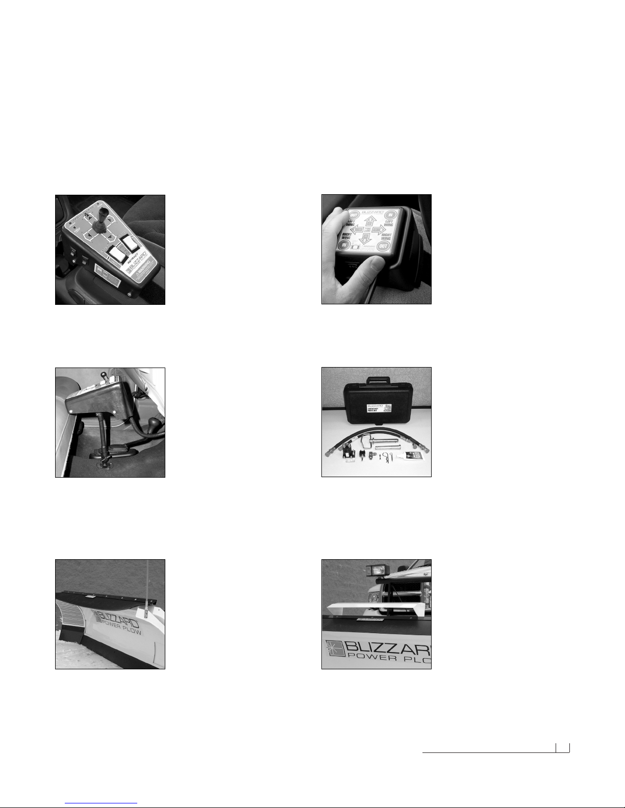
Blizzard Snowplow Airfoil
P/N 52092
Help channel air flow to your truck
radiator during the long haul over
the road. Mounted front and center,
our custom airfoil redirects air over
the top of the blade and into the
grill of your vehicle. Don’t get stuck
on the side of the road! Keep
trucking with this easy-to-install accessory. The airfoil is shipped
with complete mounting hardware.
Adjustable Pedestal Mount
(For use with all controls)
P/N 63078 (12" Shaft)
Easy-to-install and flexible, our
adjustable pedestal mount will
position your Power Plow snow-
plow control station how you want
it! Available in a 12" extension, this
quality built accessory will install
on either Blizzard Power Plow snowplow control station in minutes!
Ideal for bucket seat vehicles with low center consoles. Pedestal
accessory shipped with complete hardware and adapter plate.
Rocker Switch/Joystick
Control Station
P/N 62109
Like the touch of our standard
rocker switch control but want to
control your Blizzard Power Plow
snowplow with a joystick? Our
optional control gives you the best
of both with a 2-1/4" tall joystick
and wing operation rocker switches. Easily install the control using
our Seat Cinch™ system—a Velcro® strap that wraps around the
bench or vehicle console.
Blizzard Snowplows
Emergency Parts Kit
P/N 63075
Be prepared for unexpected plow
emergencies! This kit includes the
most common replacement parts
conveniently packaged in a small,
durable plastic case. Custom foam
insert holds the following plow
parts: Angle cylinder hose, lift cylinder hose, hitch pin w/hair pin cot-
ter, angle cylinder clevis pin w/cotter, 90˚ angle cylinder fitting, sole-
noid, Power Hitch™ toggle switch, corrosion preventive compound
(2 oz.) and 10A fuse. The compact case (13.5"x 9"x3.3") allows for
easy storage behind or under your truck seat.
Touch Pad Control Station
P/N 62141
Small and compact, the Power
Plow snowplow touch pad control
offers ergonomic comfort behind
the wheel. Whether you hold it in
your hand, strap it on your leg,
wrap it around your seat or mount
it to the dashboard, this control will
provide the flexibility you need! Control is shipped with a molded
plastic leg tray, adjustable Velcro® strap and extra Velcro® patches.
Measures 3-1/4" x 3-1/4" x 1-5/16".
Rubber Snow Deflector
P/N 52087
Plow safer and easier with our
custom rubber snow deflector.
This easy-to-install accessory
keeps snow off of your windshield
and in its place— on the ground!
Rugged and durable, the 3/8"
thick, 2-ply construction is made
to last. The one piece rubber design allows for wing clearance and
provides optimum snow deflection. The deflector is shipped with a
“Blizzard Power Plow” vinyl decal and complete mounting hardware.

02 Warning!
Warning!
Prior to operating your Power Plow snowplow, review the WARNING!
label at the passenger’s side rear of the moldboard (shown below).
Note: Read and understand all warnings indicated in this manual prior
to operating the snowplow. Warnings and cautions in the manual are
indicated by the icons shown to the left.
WARNING:
CAUTION:
1. Properly mount the snowplow prior to moving the vehicle.
2. To prevent accidental plow activation, turn the Power switch on the snowplow control
to the “OFF” position when not in use.
3. Stand clear of the attachment area when mounting the snowplow to the undercarriage
and operating the Power Hitch Connect/Disconnect switch. Failure to do so may result
in serious injury or death.
4. Securely position all mounting pins prior to operating your snowplow.
5. Do not position your body between the snowplow and the vehicle when servicing
or operating.
6. Position the snowplow in such a manner as to not block your vision or plow lights
while in transit.
7. Always travel with the wings fully retracted. Depending on local and state regulations,
you may be exceeding the legal vehicle width when the wings are fully or partially
extended.
8. Do not change the position of the snowplow while in transit.
9. Do not exceed 40 mph when transporting the snowplow.
10. Do not exceed 10 mph when plowing.
11. Always lower the snowplow when the vehicle is parked.
12. Vehicles equipped with air bags are designed to be activated in a frontal collision
equivalent to hitting a solid object or barrier at approximately 14 mph or more.
Careless or high speed driving while plowing snow, which results in vehicle impact
deceleration equivalent to or greater than the airbag deployment threshold described
above, would deploy the airbag.
The Blizzard Power Plow snowplow is protected by U.S. Patents 5,899,007; 5,638,618 and 6,276,076 B1. Other patents pending.
READ
OWNER’S
MANUAL
THOROUGHLY
PRIOR TO
OPERATING
PLOW.
Calumet, MI 49913
Do not exceed the (GVWR)
Gross Vehicle Weight Rating
or (GAWR) Gross Axle Weight
Rating including the snowplow
and ballast. Refer to your
vehicle Owner’s Manual for
the proper weight ratings.
WARNING
BLZ 1005
WARNING
Should the WARNING! label or any of the labels
that came with your snowplow become hard to
read or wear off, contact your local authorized
Blizzard dealer for replacements.

Snowplow Operation 03
Snowplow Operation
Your Blizzard Power Plow snowplow is the most advanced and versatile
snowplow on the market. The easy to use controls allow you to automat-
ically adjust the plow blade and wings into an infinite number of plowing
positions. Review the illustrations below to determine the best position for
your plowing needs.
A.
B.
C.
D.
A. Compact Position (8'- 6" Blade Width)
•Primary position when transporting
the snowplow
•For use in heavy snow conditions with poor
visibility, initial clearing and tight quarters
•Ideal application: Residential driveways,
small roads
B. WidePass™ Position (11'-3" Blade Width)
•Primary position for clearing large surfaces
•For use in light snow conditions with good
visibility, final clearing and clean-up
•Ideal application: Large parking lots,
widening roadways
C. BucketBlade™ Position (9'-10" Blade Width)
•Primary position for transporting snow
•For use in initial clearing with decent visibility,
transporting large volumes of snow, final
clean-up
•Ideal application: Roadway intersections
D. WidePass™ Position Angled with
Wing Forward
•Primary position for accelerated angled plowing
•For use in directional plowing, cornering,
diverting snow away from objects or buildings
•Ideal application: Plowing adjacent to buildings,
driveway /road intersections
***** IMPORTANT *****
To prevent premature failure of the power
contactor (solenoid), initiate the plow function
and return the rocker switch and/or joystick to
its neutral or center position. DO NOT hold a
rocker switch and/or joystick in any position
that allows the pump to continuously run
after the main blade or wing has reached its
maximum degree of movement. This will
reduce the useful life of the solenoid.

04 Unpacking & Inspection
Assembly Instructions
Unpacking & Inspection
Your Blizzard Power Plow snowplow has been packaged to withstand
transit and weather related damage. Fully inspect all components upon
receipt of your plow. In the event of shipping damage or missing parts,
immediately contact our Customer Service Department at 1-888-680-8600.
Begin unpacking and inspection in the following order:
1. Remove the shipping document from the end panel of the pallet wrap.
Retain all documentation for your records.
2. All wood framing and polyethylene material should be removed from
the pallet for easy access to the snowplow.
3. Due to the odd shaped components and size of several assembly
parts, various cable ties and corrugated material are used for scratch
resistance and package orientation. Please remove these items prior
to assembly.
4. Place the main blade assembly on a flat, level surface.
Once you have inspected all parts and removed all packaging materials,
your snowplow is ready to be fully assembled.
Pallet Wrap End Panel
The tear resistant woven polyethylene pallet wrap
contains a moisture barrier to help protect all
packaged components and keep out the most
inclement weather during shipping and storage.
The end panel of the pallet cover contains impor-
tant information regarding the snowplow model
and the plow’s serial number. Both of these num-
bers are given together. The first four digits of the
number indicated is always the plow model –
8611 and the entire number sequence make up
the serial number. The shipping document is also
attached to the end panel. Be sure to retain this
list for your records.
Snowplow Serial Number
Hydraulic Pump Serial Number
Telephone Number
Dealer/Distributor
Date of Purchase

Moldboard & A-frame Assembly 05
Moldboard & A-Frame Assembly
1. Begin the moldboard assembly by first removing each dust cap from
both of the SLIDE BOX CYLINDERS located at the center/rear of the
MOLDBOARD. Attach one 7/16"-20 x 9/16"-18 MALE O.R.B. CON-
NECTOR to each of the retract ports (#7 & #10) and one 9/16"-18 x
9/16"-18 MALE O.R.B. CONNECTOR to each of the extend ports (#8
& #9). Review the diagram below. Note: All of the hydraulic adapters
can be found packaged with the manifold assembly. Reference the
table on page 20 for proper torque specifications.
2. Connect the hoses to each of the hydraulic adapters on the cylinders.
Ports #7 & #10 receive a 1/4" x 36" HYDRAULIC HOSE (P/N 60019).
Note: Review the label on each hose for the appropriate part number.
Ports #8 & #9 receive a 3/8" x 36" HYDRAULIC HOSE (P/N 60224).
3. Next, position the PIVOT BEAM and the A-FRAME, near the mount
locations at the rear of the blade, between the two center support ribs.
Place the right and left group of hydraulic hoses (connected to the slide
box cylinders) through the 1-1/2" diameter rubber grommet openings
in the front face of the pivot beam. See the diagram to the right.
4. Position the pivot beam between the two support ribs until the con-
necting points on the beam align with those on the plow. Insert one
3/4" DIA. x 3" CLEVIS PIN through each mounting hole and secure
them with one 1/4" DIA. x 1-1/2" COTTER PIN.
Note: Mount the kickstand to the end of the pivot beam (driver’s side)
using the 1/2"-13 x 4-1/2" bolt provided. The spring, bushing and lock
nut locate on the inside of the pivot beam. Review the diagram to the
right and on page 26. Upon installation, rotate the spring loaded kick-
stand clockwise until it locks into place. Adjust the foot on the stand
arm so the height of the A-frame, at its mount points, is 12-1/2" to
level ground. Tighten both of the 1/2"-13 top lock nuts on the kickstand.
Note: To prevent the kickstand from hitting the ground before the
snowplow cutting edges, causing stress on the kickstand lock pin,
adjust the kickstand foot approximately 1/8" short of level ground.
This procedure will provide clearance for the kickstand when the
snowplow is lowered with the kickstand in the down position.
5. Position each ANGLE CYLINDER with the rod end of the cylinder
in the pivot beam and the hydraulic hose port facing away from the
Rod
#7
Base
#8 #9
Base
#10
Rod
DRIVER’S SIDE PASSENGER’S SIDE
7/16" 9/16" 9/16" 9/16"
Male O.R.B. Connector Adapter
(Ports #7 & #10)
Male O.R.B. Connector Adapter
(Ports #8 & #9)
The kickstand mounts to the side of the pivot
beam with one 1/2"-13 x 4-1/2" hex cap screw
and top lock nut. To pivot the kickstand, simply
pull the spring loaded leg out and rotate it until
the pin locks into place. The kickstand also has
an adjustable foot that can be moved to accom-
modate varying vehicle heights. Adjust the kick-
stand foot approximately 1/8" short of level ground.
This will prevent the kickstand from hitting the
ground before the plow cutting edges. The proper
height of your snowplow mounting points to level
ground should be set at 12-1/2".
1/8" Ground
Clearance
Spring Loaded
Adjustable
Pivot Beam
Kickstand
12-1/2"
Feed each group of hoses (two per side) through
the grommets in the pivot beam and up through
the openings in the A-frame. Positioning the hoses
through the pivot beam supports the hoses while
the snowplow is in use and prevents them from
dragging on the ground.

06 Moldboard & A-frame Assembly (continued)
A-frame. Secure the cylinder to the pivot beam with one 3/4" x 5"
CLEVIS PIN and one 1/4" x 1-1/2" cotter pin. Extend each cylinder
rod until the cylinder base mounting hole aligns with the hole on the
A-frame angle cylinder bracket. At this point, insert another clevis pin
and secure it with a cotter pin. Repeat the same installation for the
opposite angle cylinder.
6. Remove each dust cap from both of the hydraulic angle cylinder ports
and attach one 9/16"-18 x 9/16"-18 90˚ ADJUSTABLE ELBOW O.R.B.
ADAPTER to each port. Each adapter should be angled toward the
top of the moldboard. Connect one 3/8" x 26" hydraulic hose (P/N
60223) to each angle cylinder adapter. Be careful not to overtighten
the hose connections. Route both hoses over the TOP of each angle
cylinder. This will prevent them from hanging or being pinched.
7. Next, remove both of the plastic dust caps from the HYDRAULIC
LIFT CYLINDER ports. Attach one 9/16"-18 x 9/16"-18 45˚ ADJUST-
ABLE ELBOW O.R.B. ADAPTER to the driver’s side port (base end)
and one 9/16"-18 x 9/16"-18 MALE O.R.B. CONNECTOR ADAPTER
to the passenger’s side port (rod end). Once the adapters have been
installed on the cylinder, connect the hydraulic hoses. Note: Position
the 45˚ fitting in the cylinder port such that the hoses install directly
in the center of the A-frame access holes. A hose installed too close
to the edge of the opening may work itself free with the operation of
the lift cylinder and/or movement of the plow. The 45˚ adapter receives
a 3/8" x 17" hydraulic hose (P/N 60273). Connect the 45˚ angle on the
hose to the hydraulic adapter on the cylinder. The male connector
adapter receives a 3/8" x 15" hydraulic hose (P/N 60274). Tighten the
45˚ end of the hose to the hydraulic adapter on the cylinder. Both
hoses should be routed through the triangular openings in the A-frame.
9/16" 9/16"
Male O.R.B. Connector Adapter
Draw Latch Assembly
Draw
Pin
A-Frame
Latch
Lock Pin
A-Frame
Latch
To mount the Power Plow snowplow, the A-frame
latch should be lowered over the draw pin– this
allows the draw latch to pull the plow into the
undercarriage. Once the plow is safely attached
to the undercarriage, rotate the A-frame latch
counterclockwise until the lock pin snaps into
place. The A-frame latch is only used to
mount the plow. Do not allow the lock pin to
set behind the pin catch hole in the raised
position. The A-frame latch should always be
locked in place when not in use.
9/16"
9/16"
45˚ Adjustable Elbow O.R.B. Adapter
9/16"
9/16"
90˚ Adjustable Elbow O.R.B. Adapter
8. Begin the draw latch installation by first removing the DRAW LATCH
MOUNT PIN & SPACER from the assembly. By removing this pin, the
INNER DRAW LATCH PLATES can swing free. Proceed to remove
the INNER DRAW LATCH PLATE LIFT CYLINDER MOUNT PIN.
A-Frame
Latch Pull Pin
A-Frame
Latch
Outer Draw
Latch Plate
Inner Draw
Latch Plate
Draw Latch Mount Pin
1" DIA. x 4-21/32"
Inner Draw Latch
Plate Lift Cylinder
Mount Pin
3/4" DIA. x 2-1/2"
Draw Latch Arm
Pivot Pin
3/4" DIA. x 2-1/2"
Hydraulic
Lift / Lower
Cylinder
Draw Pin
1" DIA. x 6-1/2"
3/16" x 2-1/2"
Cotter Pin
Hex Head Cap Screw
3/4"-10 x 4-1/2"
1" O.D., 25/32" I.D. x 5/8"
Spacer
Clevis Pin
3/4" x 3-41/64" 1/4" x 1-1/2"
Cotter Pin

Moldboard & A-frame Assembly (continued) 07
72
1
CV4
8
CV2
3
4
10
9
7/16"
9/16"
9/16"
9/16" 9/16" 9/16"
7/16" 9/16"
9/16"
9/16"
Adjustable Elbow
O.R.B. Adapter (Port #2)
Male O.R.B. Connector Adapter
(Ports #3,4,8,9)
Male O.R.B. Connector Adapter
(Ports #7 & #10)
90˚ Swivel Elbow
(Ports #7 & #10)
Male Extra Long
Elbow Adapter
(Port #1)
Position the plates on either side of the lift/lower cylinder rod and insert
the pin through the plates and cylinder rod. With the cylinder connected
to the inner draw latch plates, rotate the draw latch assembly toward
the draw latch mount holes on the A-frame. Align the holes in the outer
draw latch plate with those of the inner draw latch plates and the
A-frame. Note: The A-FRAME LATCH, located at the rear center of
the A-frame, should be raised up to insert the draw latch mount pin.
Pull the A-FRAME LATCH PULL PIN out and rotate the latch counter-
clockwise if it is locked into position. Secure the assembly to the A-frame
by replacing the draw latch mount pin and spacer. Reset the A-frame
latch so the A-frame latch pull pin locks into place.
Once you have completed the draw latch installation, proceed to assemble
the manifold. The manifold, pump and coil harness have been joined
together at the factory; however, the manifold contains several components
that you will need to install prior to securing the assembly to the A-frame.
9. Each of the 8 HOSE PORTS on the HYDRAULIC MANIFOLD are
covered with stretch wrap. Remove the wrap and install the appropriate
fitting (illustrated below) in its respective port.
Note: All ports are identified by a stamped number on the manifold.
The numbers also identify the hydraulic functions, which can be ref-
erenced on the label under the hydraulic pump and manifold cover
(see illustration on page 8).
Note: The gray arrows shown on the manifold illustration below
indicate the direction the 90˚ adapters should face to receive the
hydraulic hoses.
90˚ Swivel Elbow
(Ports #3,4,8,9)
Printed
Label
All of the hoses shipped with the snowplow con-
tain a printed label (with a part number) applied
to the hose. Install the following hoses to their
respective ports on the manifold:
Hose P/N 60223 Ports #1 & #2
Hose P/N 60273 Port #3
Hose P/N 60274 Port #4
Hose P/N 60019 Ports #7 & #10*
Hose P/N 60224 Ports #8 & #9*
Note: See diagram on page 8.
Installing The Manifold Adapters
There are a total of 18 hydraulic adapters to
install. All of the adapters can be found packaged
with the manifold assembly. Remove the protective
stretch wrap from the manifold in a clean area.
DO NOT let any foreign objects enter into the
open ports. The valves can become contaminated
and greatly hinder the plow’s performance.
Review the table on page 20 for proper torque
specifications.

08 Moldboard & A-frame Assembly (continued)
10. Next, align the mount holes in the pump with the holes in the hinged
bracket, located on the A-frame. Note: To help facilitate the pump mount,
first angle the hinged bracket as needed and tighten the bracket
hardware, locking it in place.
CAUTION:When installing the manifold between the mount
brackets on the A-frame, hold the manifold at the sides of
the block. Never handle the manifold by coils. Doing so can
cause a solenoid cartridge to bend, causing the cartridge
to stick when activated.
Secure one 3/8"-16 x 3/4" hex head cap screw and 3/8" flat washer
through the top mount hole in the bracket and into the pump. Insert
one 3/8"-16 x 1-3/4" threaded stud and 3/8"-16 jam nylon insert lock
nut through the bottom mount hole in the bracket and into the pump.
The threaded stud should bottom out in the pump. Note: A medium
strength threadlocker, such as Loctite® 242® should be used on both
of the pump mount fasteners.This will help prevent the fasteners from
working free.
Sequence Valve & Hydraulic Hose
Identification Guide
Calumet, Michigan 49913 BLZ 1055
S10
RV1
S9
S4
S6
S2
RV5 FC
S5
Pressure Gauge
Quick Connect
Clockwise - Decreases Plow Drop Speed
Counterclockwise - Increases Plow Drop Speed
RV2 S3 RV3
S8
RV4
S1
72
1
CV4
8
CV2
3
4
10
9
Function
Right Angle - Left Cylinder
Left Angle - Right Cylinder
Raise - Lift Cylinder (Base)
Lower - Lift Cylinder (Rod)
Left Slide Box Retract
Left Slide Box Extend
Right Slide Box Extend
Right Slide Box Retract
NOTE: Energize the following solenoids for the functions:
Left Wing Pressure Relief
Left Wing Anti-Cavitation
Right Wing Anti-Cavitation
Right Wing Pressure Relief
Angle Relief
Left Wing Check Valve
Left Slide Box Check Valve
Right Wing Check Valve
Right Slide Box Check Valve
HYDRAULIC HOSES
RELIEF & CHECK VALVES
Function
Right Slide Box Retract
Right Slide Box Extend
Angle Left - Right Cylinder
Angle Right - Left Cylinder
Float
Raise
Lower
Left Slide Box Retract
Left Slide Box Extend
VARIABLE FLOW CONTROL VALVE
Adjustable Plow Drop Speed
Port
1
2
3
4
7
8
9
10
RV1
RV2
RV3
RV4
RV5
CV1
CV2
CV3
CV4
Valve
S1
S2
S3
S4
S5
S6
S5 & S8
S9
S10
FC
NOTE: Check valves CV1 & CV3 are not illustrated. Both valves are located on
the opposite side of the manifold in the diagram shown below.
11. Once the pump and manifold assembly is in place, connect the
hydraulic hoses to their respective adapters on the manifold. Review
the label under the pump cover to identify which hoses connect to
each port. Note: All hoses, except #1 & #2 (angle cylinders) should
be routed through the triangular openings in the A-frame. Position
these hoses over the A-frame angle and to their respective manifold
ports. Note the positions for the rod- and base-end slide box hoses.
The hoses that operate the retract functions (rod) of the cylinders are
closest to the base of each cylinder. Likewise, the hoses that operate
the extend functions (base) of the cylinders are closest to the rod of
each cylinder. Review the diagram on page 5 and the hose installation
list on page 7.
When installing the manifold between the mount
brackets on the A-frame, DO NOT handle the
manifold by the coils. The solenoid cartridges
can bend, causing them to stick when activated.
Always carry the manifold by the sides of the
aluminum block.
A medium strength threadlocker, such as Loctite®
242®, should be used to properly secure the
mount hardware for the pump and manifold. This
will help prevent the hardware from working free
from vibration and plow use. Apply a liberal
amount of threadlocker to both threaded fasten-
ers and the threads in the pump (top diagram).
The manifold receives two 3/8"-16 x 1-1/4" hex cap
screws—one on each side of the A-frame. Like-
wise, use threadlocker on these fasteners and
the tapped holes in the manifold (bottom diagram).
Use Loctite®on
Manifold Mount
Hardware
Apply Loctite®
To Pump Mount
Hardware Upon
Installation

Moldboard & A-frame Assembly (continued) 09
12. Next, secure the manifold to the A-frame. Remove both 3/8" flat
washers, 3/8" split lock washers and 3/8"-16 x 1-1/4" hex head cap
screws from the manifold and align the mount holes with the A-frame
brackets. Position the DIODE PACK MOUNT BRACKET against the
outside of the A-frame bracket on the driver’s side. Note: Both of the
prongs should be facing up. Align the outside hole on the diode bracket
with the holes on the A-frame and manifold. Properly replace and
tighten all hardware. Note: A medium strength threadlocker, such as
Loctite® 242® should be used to secure the manifold mount fasteners.
13. Hook each EXTENSION SPRING to the receiving holes located on
the pivot beam and connect the opposite end of the spring to their
respective SPADE BOLTS. Install the 5/8"-11 x 6-3/8" spade bolts
through the EXTENSION SPRING MOUNTING ANGLE on the top rear
of the blade. Secure each spade bolt by placing one 5/8" flat washer
on the bolt and thread one 5/8"-11 nylon insert lock nut. Tighten each
lock nut until a piece of paper can pass between the 3th & 4th coils
on the spring.
14. Install the flexible BLADE GUIDES at each end of the moldboard.
Insert the 5/16"-18 x 1" hex head cap screw through the holes at the
top of the wing reinforcement rib. Tighten all screws using the nylon
insert lock nuts provided.
Congratulations! You have successfully completed half of the installation.
Don’t quit now, you’re nearly out of the garage!

10 Electrical Assembly - Plow Harness
Electrical Assembly - Plow Harness
1. Begin the electrical assembly by connecting the RED POWER WIRE
from the PLOW ELECTRICAL HARNESS to the PUMP motor terminal
stud using the hardware provided on the pump.
2. Place one 3/8" INTERNAL/EXTERNAL TOOTH LOCK WASHER, the
BLACK GROUND WIRE (from the harness) and the RED GROUND
WIRE on the COIL WIRE HARNESS (from the manifold) over the
tapped hole on the pump and secure the ground using one 3/8"-16 x
3/4" hex head cap screw.
3. Remove the hex jam nut and external tooth lock washer from the
POWER HITCH CONNECT/DISCONNECT TOGGLE SWITCH and
insert it through the back of the mounting bracket on the A-frame. Align
the notch in the key washer on the switch to the notch on the bracket.
Replace the lock washer and jam nut and tighten until the switch is
firmly in place. Next, attach the connector on the plow harness to the
switch. Note: Use caution when making the connection. Switches can
break if done forcefully.
4. Continue the harness installation by connecting the PLASTIC FEMALE
ELECTRICAL CONNECTOR on the harness to the PLASTIC MALE
ELECTRICAL CONNECTOR found on the coil wire harness.
5. Finalize the harness installation by sliding the DIODE PACK over the
diode pack mount bracket located behind the connect/disconnect toggle
switch. Position the wire harness braid in the notch on the switch
bracket and secure it with a cable tie.The diode pack mount bracket
contains an extra hole for a cable tie. Use it to secure the diode pack.
6. To install the PUMP & MANIFOLD COVER, align the notches in the
cover with the welded bolts on the A-frame brackets. Secure the cover
with two 3/8" FLANGED WING NUTS. Verify the cover is positioned
over the protective toggle switch hood. Pop the front of the cover on
the threaded stud and secure it with the remaining wing nut.
Congratulations! You have just completed building the finest snowplow
available! However, the vehicle wire harness still needs to be installed.
That is the focus of the second half of the electrical assembly instruction.
Diode Pack
Mount Bracket
Draw Latch
Toggle Switch
Mount Bracket
The diode pack (on the plow harness) clips onto
the diode pack mount bracket. Place a cable tie
through the hole at the end of the bracket and
over the pack to secure it in place.
The draw latch toggle switch installs through the
rear of the bracket with the protective hood. Align
the key washer with the slot cut in the bracket to
prevent the switch from turning. Secure the
switch with the hardware provided. Note: Use the
square notch in the bracket (below the protective
hood) to position the braided harness. Use another
cable tie to hold the harness against the bracket.
The Pump Cover Installs Over
The Top Of The Draw Latch
Switch Bracket
To properly secure the pump and manifold cover
on the A-frame, position the cover over the top of
the protective hood on the draw latch switch
mount bracket. Align the slots in the cover with
the welded bolts on the A-frame brackets—
secure the cover using three flanged wing nuts.

Electrical Assembly - Vehicle Harness 11
Electrical Assembly - Vehicle Harness
CAUTION: Always perform the vehicle wire harness assem-
bly with the vehicle off and the keys out of the ignition. Use
caution when testing the electrical wires for the vehicle’s
headlight functions.
1. Begin the installation of the electrical harness under the hood. Insert
the WHITE POWER CONNECTOR & RED POWER WIRE (with FUSE)
end of the harness through the driver’s side fire wall access panel into
the vehicle cab. Note:You may need to widen an opening or cut access
to the cab interior to facilitate the assembly. Loosely position the
remaining portion of the harness over the driver’s side fender well and
place the MOLDED RUBBER POWER CONNECTOR near the bumper.
Note: Keep the plow and vehicle rubber power connector pins lubri-
cated with a liberal amount of dielectric grease. Always replace the
protective RUBBER WEATHER CAPS when the plow is disconnected
from the vehicle.
2. Next, attach the POWER CONTACTOR (SOLENOID) to the driver’s
side wheel well or engine fan guard using two 12-14 x 3/4" hex washer
self-drilling screws. Note: Some model vehicles provide mounting
locations for accessory components. Always mount the solenoid with
the terminals facing up. This will extend the useful life of the solenoid.
Connect the 24" BLACK GROUND WIRE to either small terminal on
the solenoid and attach the opposite end to the vehicle with one hex
washer self-drilling screw. Locate the BROWN/WHITE PUMP SOLE-
NOID ACTIVATION WIRE on the wire harness and position the eyelet
over the remaining small terminal on the contactor. Secure it with the
hardware provided on the solenoid.
3. Proceed to connect the BLACK VEHICLE WIRE HARNESS GROUND
WIRE to the negative terminal on the vehicle’s battery. Cut the wire to
length and crimp a 3/8" DIA. END RING TERMINAL on the wire. It is
also recommended that the ring terminal be soldered. Note: The har-
ness should be secured to the vehicle prior to taking the necessary
measurement. Measure the distance needed for the RED POWER
WIRE to reach the solenoid and properly secure an end ring terminal
to it. Connect the power wire to either large terminal on the solenoid.
CAUTION: Do not fasten the wire harness to areas that come
in contact with moving engine parts or possess extreme
heat.The harness could become tangled and/or melt causing
electrical failure and vehicle damage.
4. Attach and solder an end ring terminal to both ends of the remaining
length of the red 4 gauge wire. Connect one end of the wire to the
open terminal on the solenoid and the remaining end to the positive
terminal on the battery.
5. With the vehicle harness secured to the truck, position the MAIN
LIGHTING HARNESS such that both of the large, gray VEHICLE
HEADLIGHT CONNECTORS are near the truck headlights and the
smaller, black PLOW HEADLIGHT CONNECTORS are near the grill
of the vehicle.
AB
C D
Heavy-Duty Power Contactor (Solenoid)
There are four wires that need to be attached to
the power contactor:
(A) Red Power Battery Wire
(B) Vehicle Wire Harness Red Power Wire
(C) 24" Black Ground Wire
(D) Brown/White Pump Solenoid Activation Wire

12 Electrical Assembly - Vehicle Harness (cont.)
6. Plug the 3 TERMINALS (GREEN/YELLOW WIRES), from the vehicle
wire harness, into the BLACK HEADLIGHT RELAY RECEPTACLES
on the main lighting harness. Remove the white secondary lock from
each receptacle, plug one terminal into the remaining position on each
receptacle and reposition the secondary lock. With the terminals in
place, plug each HEADLIGHT RELAY into the receptacles. Securely
mount the receptacles to the vehicle with the terminal wires facing
down and the relays facing up. Installing the relays in this position will
allow moisture to drain from the relay.
7. Next, remove the front directional light assembly on the driver’s side
of the vehicle. Feed the VIOLET, turn light wire and GRAY, run light wire
from the main lighting harness through the opening in the directional
light housing. At this point, use a test light or ohm meter to determine
the proper wires in the vehicle’s electrical system to splice into. Once
you have identified the proper wires, position one end of the turn or
run light wire into a SPLICE LOCK CONNECTOR provided. Attach
the vehicle wire to the opposite side of the splice lock connector.
Complete the splice by pinching both wires together and locking the
connector. Repeat the splice procedure for the remaining wire. The
passenger’s side directional light assembly requires the same instal-
lation; however, only one wire, the PINK, turn light, needs to be spliced.
8. Connect the vehicle headlights to the main lighting harness using a
HEADLIGHT ADAPTER KIT. Due to differences in the construction
of the adapter kits, and the various make and model vehicles Blizzard
snowplows are installed on, a headlight adapter kit is not packaged
with your snowplow. Contact your local Blizzard dealer to obtain the
appropriate adapter for your vehicle.
9. Begin the adapter kit installation by removing the existing vehicle head-
light connector from the headlight. Attach the HEADLIGHT ADAPTER
CONNECTOR to the existing vehicle headlight connector. Next, plug
the BLACK, FIVE-PIN CONNECTOR on the headlight adapter into
the gray, five-pin connector on the vehicle wire harness. Lastly, plug the
HEADLIGHT ADAPTER CONNECTOR into the vehicle headlight re-
ceptacle. Note: If more than one plug is present, match the colors of
each connector (ie gray to gray, black to black, Chevrolet daylight run-
ning is clear to gray). Repeat the installation for the opposite headlight.
10. Once the headlight adapter connections are completed, proceed to
secure the braided harness to the vehicle. Safely route all harness
lengths around the engine components and attach them to the vehicle
with cable ties. Extend the PLOW HEADLIGHT CONNECTORS, from
the main lighting harness, through the grill of the vehicle and position
the HARNESS POWER PLUG and WEATHER CAP near the bumper.
Cable tie the power plug to the vehicle bumper or tow hook to keep
the harness from hanging too low.
11. Return to the driver’s side cab interior to install the remainder of the
vehicle wire harness. Connect the RED POWER WIRE (with 15 AMP
FUSE) to a switched power source with a minimum of 15 amps. Note:
The red power wire MUST be fused and switched on and off with
ignition. Secure all loose wires under the dash.
Snowplow Hitch Pin
& Hair Pin Cotter
In the event you should lose hydraulic power while
snowplowing, raise the snowplow into a pile of
snow and insert one of the two hitch pins provided
with your plow. The pin will lock the plow in a tem-
porary raised position until proper service can be
performed to restore hydraulic power. Note: For
clarity, the draw latch is not illustrated.
The vehicle wire harness is packaged with three
12V quick connect, sealed headlight relays. The
relays install into the black receptacles located on
the main lighting harness. Review the diagram on
page 32.

Electrical Assembly - Vehicle Harness (cont.) 13
12. Next, install the LIGHT TOWER. Position the tower arms into the
receiving pockets located on the undercarriage. Each pocket has a
lock pin that secures both light tower arms. Pull out and twist each
handle to temporarily unlock the pins. Place the light tower into the
pockets and relock the pins. See your local Blizzard dealer for com-
plete installation instructions for your vehicle undercarriage.
13. Proceed to install the PLOW HEADLIGHTS. Align one HEADLIGHT
BALL STUD MOUNT ADAPTER on the light tower tube with the
mounting hole and insert the threaded stud through each. Secure the
headlight with one 7/16" external tooth lock washer and hex nut.
Note: All snowplows are shipped with two BLACK VINYL CAPS that
install at either end of the light tower. Connect the terminals from the
plow lights to the terminals on the main lighting harness. Repeat the
installation for the opposite headlight.
14. Next, position the ROCKER SWITCH CONTROL STATION on the front
radius of the seat. Wrap the VELCRO® STRAP around the bench,
through the 2" metal D-ring and fasten. Finally, connect the white
power connector from the vehicle wire harness to the connector on
the control station. The power switch should be in the “MIDDLE” or
“OFF” position. Note: The operation of the draw latch can only be
controlled when the power switch is located in the “UP” position and
the “RAISE/LOWER” rocker switch is in the neutral or center position.
See the diagram below.
This completes the electrical assembly installation for the vehicle wire
harness and main lighting harness. You are now ready to perform all of
the test functions on the snowplow.
Vinyl
Cap
The black vinyl caps provided with your snowplow
install at each end of the light tower. Adjust the
plow headlights as desired, secure each with
hardware provided and finish the installation by
capping the light tower ends.
Power Hitch Operation
System Power OFF
System Power ON
The Power Hitch will not operate if
the Raise/Lower rocker switch is
in the “LOWER” or float position.
BLZ 1053

14 Testing The Snowplow
Your Blizzard Power Plow snowplow will use
approximately 4 quarts of Blizzard Rapid Action
Hydraulic Oil. Note: The part number issued on
the quart bottle label has been changed to P/N
63070. Blizzard hydraulic oil is also available by
the case (P/N 63071), gallon (P/N 63072) or gallon
case (P/N 63069). See your local authorized
Blizzard dealer for price and availability.
Testing The Snowplow
1. Fill the HYDRAULIC PUMP FLUID RESERVOIR with BLIZZARD
SNOWPLOW RAPID ACTION HYDRAULIC OIL (P/N 63070) until it
is approximately 3/4" from the top of the tank. Replace the cap on the
reservoir. Proceed to remove the weather caps from each of the plow
and vehicle wire harnesses and connect the plugs. Start the vehicle
and turn the POWER SWITCH on the control station in the cab to the
“ON” position. You now have power to the snowplow. Once all of the
hydraulic functions have been executed, the system will have been
filled with approximately 4 to 4-1/2 quarts of hydraulic oil.
2. To raise the POWER HITCH on the snowplow, turn the power switch on
the control station to the “UP” or “ON” position. Note: The “RAISE/
LOWER” rocker switch must be in the neutral or center position for the
Power Hitch to operate. Push and hold the toggle switch on the A-frame
upward into the “CONNECT” position. Notice the action of the fluid in
the reservoir. By activating the initial hydraulic function, the fluid begins
to fill the system. Push and hold the toggle switch in the “DISCONNECT”
position, the Power Hitch will lower. Refill the reservoir until the fluid
is approximately 3/4" from the top of the tank.
3. Position the vehicle such that the Power Hitch is below the push beam
and the mounting points on the A-frame are in line with the mounting
points on the undercarriage. Pull out the A-FRAME LATCH PIN and
rotate the A-FRAME LATCH clockwise until the latch is resting on the
DRAW PIN (See diagram on page 16). Move the snowplow in position
by activating the Power Hitch connect switch and release.
WARNING: Always use caution when operating the Power
Hitch CONNECT/DISCONNECT switch. Keep your hands and
feet away from the operation of the draw latch and the main
blade. The action of the draw latch moves the snowplow in
position for proper attachment to the vehicle. Failure to
follow this caution may result in serious injury or death.
The Power Hitch will raise until it hits the push beam and the DRAW
LATCH FINGERS will pull the plow into the vehicle. The mounting
points on the plow and vehicle are now positively aligned. Rotate the
A-frame latch counterclockwise until the latch is in the raised position.
Note: The A-frame latch pin should always lock in place. Do not set
the pin past the lock point on the A-frame. Insert the two HITCH PINS
through the mounting holes on the A-frame and secure each with one
hair pin cotter. The snowplow is now securely mounted to the vehicle.
4. Return to the interior of the vehicle. With the plow securely in place, you
can now execute the remaining functions of the snowplow. The system
power on the control station should be in the “ON” position. Next, raise
the plow to its maximum height by pushing and holding the “RAISE”
rocker switch on the control station. Initiate the driver’s side wing by
pushing and holding the “LEFT WING EXTEND” rocker switch until the
wing pivots forward. Notice the staggered pace the wing extends. The
hydraulic fluid is filling the hose and replacing the air in the system.

Testing The Snowplow (continued) 15
Push and hold the “LEFT WING RETRACT” rocker switch to return the
wing. Continue testing the remaining rocker switch functions. Monitor
the fluid level in the reservoir and fill to 3/4" from the top of the tank if
needed. Also, look for any hydraulic fluid leaks around the manifold,
pump, hydraulic hoses and all cylinders.
5. Lastly, check that the vehicle and plow headlights are in proper work-
ing condition including the turn signals. If necessary, adjust the plow
headlight beams with the plow in the raised position.
Congratulations on a successful assembly and installation! Once all of the
blade and electrical functions have been tested your Blizzard Power Plow
snowplow is ready for action. Should you need additional support during
a plow assembly or undercarriage installation, contact your local authorized
Blizzard dealer.
R
E
T
R
A
C
T
E
X
T
E
N
D
E
X
T
E
N
D
BLZ 1010
WARNING
To prevent accidental plow activation, turn POWER
switch to the “OFF” position when not in use.

16 Power Hitch™ Instruction
Power Hitch™Instruction
Prior to operating your Power Plow snowplow review the Mounting &
Dismounting Instructions label at the driver’s side rear of the moldboard.
MOUNTING & DISMOUNTING
INSTRUCTIONS
Power Hitch Raises & Lowers
Behind Undercarriage Push Beam
MOUNTING
1. Position vehicle close to the plow and align mounting points on the undercarriage and
A-frame. Verify that the plow kickstand is in the lowered position. Turn vehicle ignition off.
2. Turn power supply switch on the main plow control unit in the vehicle to the “OFF” position.
3. Remove protective weather caps and make electrical connection at the plow and vehicle.
4. Turn the vehicle ignition, and the power supply switch on the control unit, to the “ON”
position. Pull the A-frame latch lock pin outward and verify that the A-frame latch lowers
over the draw pin.
5. Activate the Power Hitch on the A-frame by pushing and holding the “CONNECT/
DISCONNECT” switch (on the pump cover housing) upward. CAUTION: Keep
fingers away from plow and truck mounting points. Power Hitch will
automatically pull the plow into the receiving points on the truck
when activated. Insert both hitch pins through the positively aligned holes
on the plow and undercarriage and secure each with a hair pin cotter.
6. With the plow securely mounted, slightly lower the Power Hitch to relieve
tension on the A-frame latch, pull the latch lock pin and raise the A-frame
latch until it locks into position. Raise the Power Hitch and verify that the
draw latch is fully engaged behind the push beam on the vehicle. Rotate
the kickstand counterclockwise until it locks into place. The plow is now
properly mounted and ready to operate.
DISMOUNTING
1. Lower the plow on a flat, level surface to dismount. Turn vehicle ignition off.
2. Pull the kickstand lock pin outward and rotate the kickstand clockwise. Release the pin
to lock kickstand in place. Remove both hitch pins from the A-frame and undercarriage.
3. Turn the vehicle ignition and the power supply switch on the control unit to the “ON”
position. Activate the Power Hitch by pushing and holding the “CONNECT/DISCONNECT”
switch downward. CAUTION: Keep fingers away from plow and truck mounting points.
Verify that the draw latch is fully disengaged from behind the push beam on the vehicle.
4. Turn power supply switch on the main plow control unit in the vehicle to the “OFF” position.
5. Disconnect electrical cords at the plow and vehicle. Replace protective weather caps.
Adjustable
Kickstand
Draw
Latch
K
E
E
P
F
I
N
G
E
R
S
A
W
A
Y
!
BLZ 1023
A-Frame Latch
Lock Pin
Plug To Vehicle
Wire Harness
CONNECT/
DISCONNECT
Toggle Switch
A-Frame Latch
Rotates Clockwise
And Hooks Onto
Draw Pin
Draw
Pin
A-Frame
Latch
Lock Pin
A-Frame
Latch
TM
Should the Mounting & Dismounting Instructions
label or any of the labels that came with your
snowplow become hard to read or wear off, contact
your local authorized Blizzard dealer for
replacements.

Notes 17
Notes

18 Regular Maintenance
Regular Maintenance
Maintenance Schedule
Maintenance Performed Date
Your Blizzard Power Plow snowplow has been designed for years of rugged,
dependable service with low maintenance. To ensure proper working condition,
follow the maintenance guidelines below and on the next page.
CAUTION: Always follow the maintenance guidelines in a timely
fashion. Failure to observe maintenance guidelines may result in
poor snowplow operation, increased component wear or possibly
lead to part failure.
Routinely inspect the following items – perform maintenance as needed:
1. All fasteners, pins, nuts and bolts for tightness. See the recommended
maximum bolt torque chart on page 20.
2. All hydraulic hoses and hydraulic hose adapters for wear and leaks. See
the recommended hydraulic adapter torque values on page 20.
3. All cylinders for leaks; inspect rod ends for corrosion and pitting.
4. Cutting edges and plow shoes for wear. Do not discard plow shoe washers.
These should be retained for different shoe adjustments.
5. Clean and lubricate all electrical plugs, headlight connections, ground and
battery cables, solenoid connections and switch connections to prevent
corrosion. Apply dielectric grease for every 25 hours of snowplow use.You
may need to grease more frequently depending on your plowing environment.
6. Lubricate all pins and bushings to prevent corrosion and to maintain con-
sistent operation, including the A-frame latch. The inner slide boxes should
also be lubricated to provide free travel. A NLGI Grade 2 multi-purpose
lithium complex grease with molybdenum (MPGM) is recommended for
lubrication.
7. Clean and cover deep scratches or exposed metal with Blizzard Snowplow
white (P/N 61219) or black (P/N 63073) touch-up paint. Contact your local
Blizzard dealer for availability.
8. Check the hydraulic oil level in the hydraulic pump fluid reservoir. Fill the
fluid to within 3/4" from the top of the reservoir. Do not exceed this level.
Never mix different types of fluids. Contact your local dealer for replace-
ment Blizzard Snowplow Rapid Action Hydraulic Oil (P/N 63070).
9. Check the trip spring adjustment. Properly adjusted tension will allow a
sheet of paper to pass between the 3rd and 4th coils of the spring.
10. Each wing uses one extension spring to help return it from the forward or
scoop position. Adjust the tension on the installed spring as needed or
install and optional second extension spring for increased return speed.
11. To adjust the snowplow drop speed, use the variable flow control valve
(FC) on the manifold (see label under pump & manifold cover). Turn the
dial on the valve clockwise to decrease the drop speed. Turn the dial
counterclockwise to increase the drop speed. See the Troubleshooting
Guide on page 38 & 39 for additional instructions.
12. Do not allow snow and ice to build-up on the pump and manifold cover.
Excessive build-up may cause bumper damage when the plow is raised.
Table of contents
Other Blizzard Snow Blower manuals

Blizzard
Blizzard 69982 User manual

Blizzard
Blizzard POWER PLOW 810 Supplement

Blizzard
Blizzard POWER PLOW 810SS Supplement

Blizzard
Blizzard SPEEDWING 8600SW User manual

Blizzard
Blizzard POWER PLOW 810-1 Service manual

Blizzard
Blizzard 7600LT User manual

Blizzard
Blizzard SPEEDWING 8600SW User manual

Blizzard
Blizzard POWER PLOW 8100PP User manual

Blizzard
Blizzard B54 Product manual

Blizzard
Blizzard 760TR Service manual