i Table of Contents
Table of Contents
01 Snowplow Operation
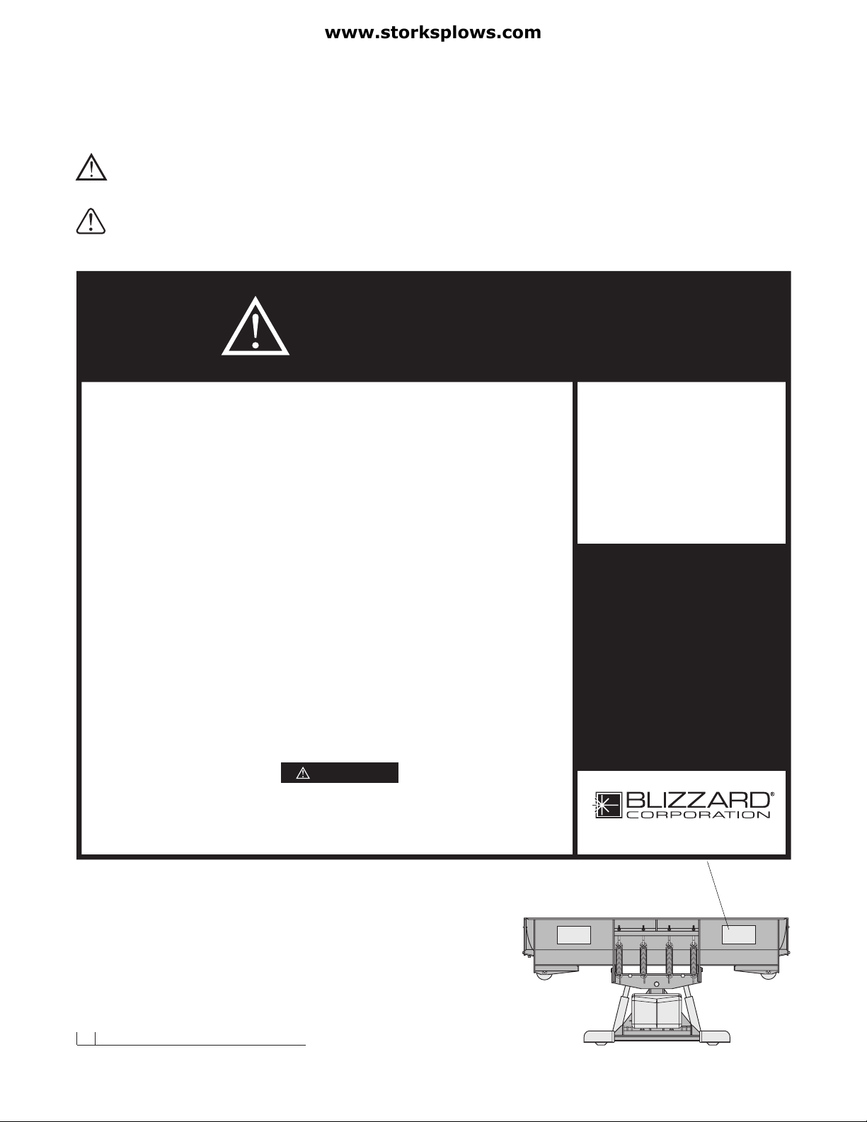
02 Warning!
Assembly Instructions
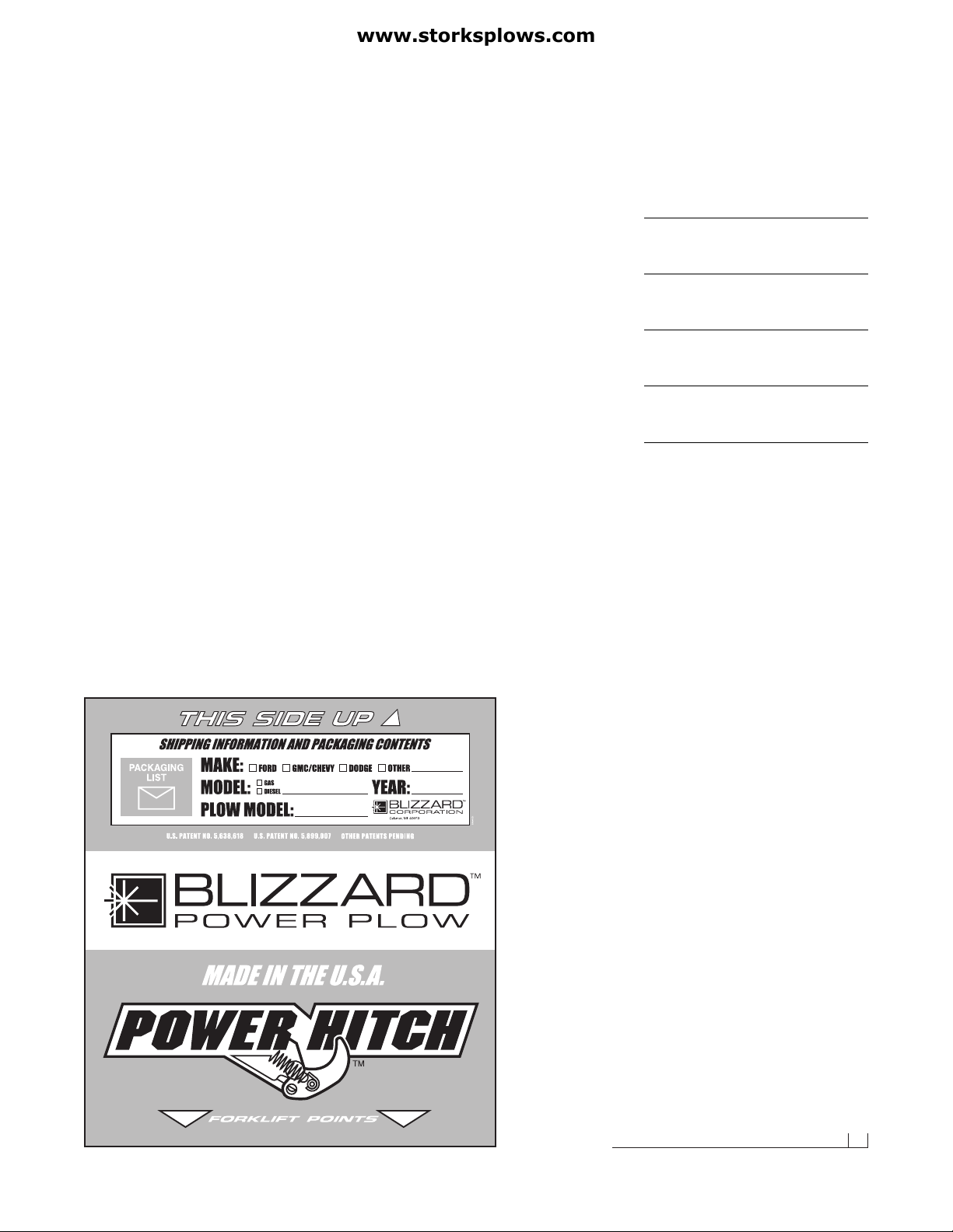
03 Unpacking & Inspection
04 Moldboard & A-frame Assembly
08 Electrical Assembly - Plow Harness
09 Electrical Assembly - Vehicle Harness
12 Testing The Snowplow
13 Mounting & Dismounting Instructions
Maintenance & Plow Specifications
14 Regular Maintenance
15 Storing Your Snowplow
16 Plow Specifications
Plow Diagrams & Part Lists
17 Model 810 Parts List
21 Hydraulic Manifold Detail
22 Model 810 Assembly Schematic
24 Coil Harness Wire Schematic / Hydraulic Manifold Schematic
Electrical Diagrams
25 Molded Plug Pin Locations (2001-2002)
26 Plow Harness (2000-2002)
27 Plow Harness Wire Schematic (2000-2002)
28 Main Lighting Harness - Relay Version (2001-2002)
29 Main Lighting Harness Wire Schematic (2001-2002)
30 Vehicle Harness - Relay Version (2001-2002)
31 Vehicle Harness Wire Schematic (2001-2002)
32 On/Off Switch Leads & Ground Lead (2001-2002)
Undercarriage Assembly Instructions
33 Technical Service Bulletin - Ford Blocker Beam™
34 1987-1991 Ford F-250 & F-350 Series
36 1992-1998 Ford F-250 & F-350 Series
38 1999-2002 Ford F-250 & F-350 Series
40 1999-2002 Ford F-450 & F-550 Series
42 1982-1987 Chevrolet/GMC C20/C30 & K20/K30
44 1988-1998 Chevrolet/GMC 2500 & 3500 Series,
1999-2000 Chevrolet/GMC 3500 Series
46 1988-2000 Chevrolet/GMC 1 Ton Heavy-Duty 2WD
48 1999-2002 Chevrolet/GMC 2500 Series
50 1979-93 Dodge 2500 & 3500 Series
52 1994-2001 Dodge 2500 & 3500 Series
Troubleshooting
54 Troubleshooting Guide
Warranties
56 Limited Consumer Warranty
57 Commercial Warranty
Introduction
Congratulations on purchasing the
most advanced snowplow available!
The Blizzard Power Plow is clearing
new trails for innovative design,rugged
durability, quality craftsmanship and
superior performance. Our exclusive
products are manufactured and tested
in Michigan’s Upper Peninsula, the
snow capital of the Midwest. With an
annual snowfall averaging over 250,"
we couldn’t imagine building snow re-
moval products anywhere else!
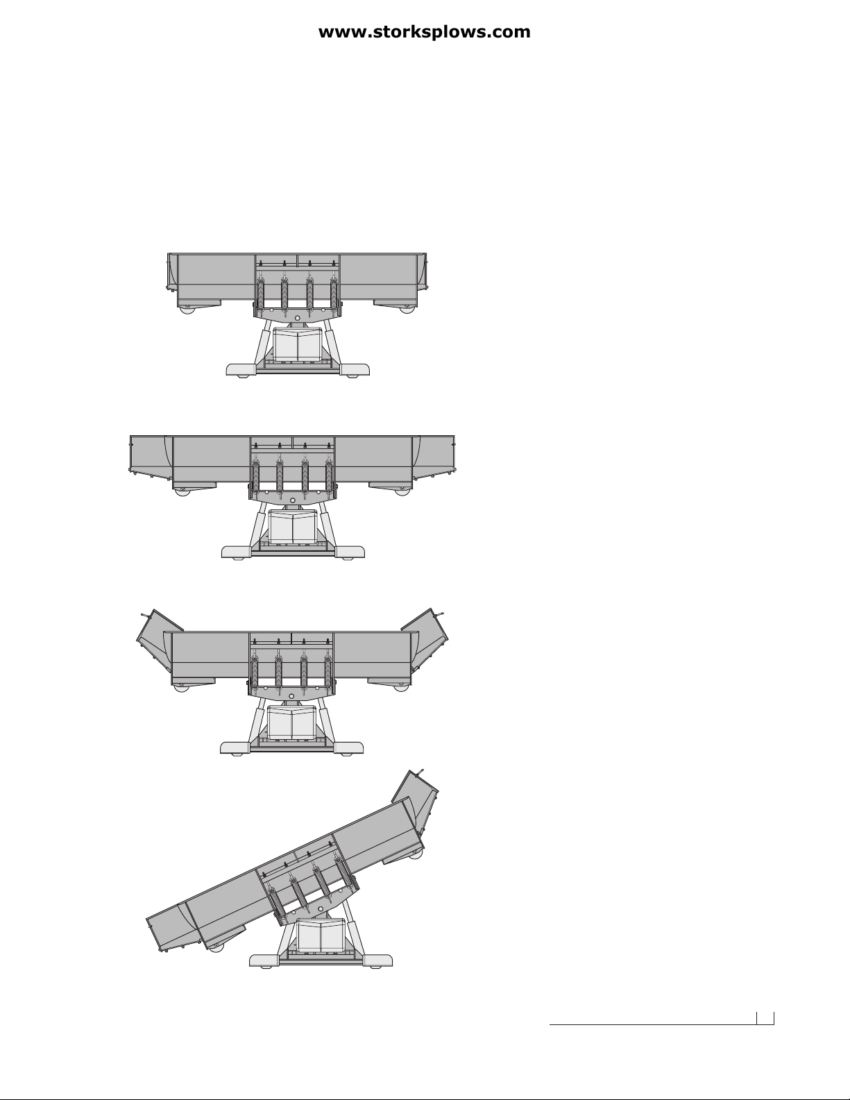
Your Blizzard Power Plow is equipped
with versatile features designed for
years of dependable service. The
hydraulic draw latch mounting system
positively aligns the plow for fast
installation or removal. Twelve-inch
expanding wings automatically trans-
form a compact 8' blade into a massive
10' machine. Also, the independent
wings can pivot forward to form our
9'-3" BucketBlade™ position. Now you
can carry more snow even further.
Safety features include full moldboard
trip action, enclosed hydraulics and
automatic cylinder pressure relief.
To ensure years of optimum snowplow
performance, review the contents of
this manual. It contains assembly infor-
mation, detailed diagrams, complete
parts listings, maintenance guidelines
and troubleshooting tips.
Should you need additional information,
contact your local Blizzard Power Plow
Dealer. Their knowledgeable staff is
well informed on the latest Power Plow
information. They are also your source
for replacement parts, technical assis-
tance and all service repairs.
Comments, suggestions or concerns?
Address all correspondence to:
Blizzard Corporation
Customer Service Department
95 Airpark Boulevard
Calumet, MI 49913
(888) 680-8600
(906) 482-5555
(906) 482-5445 Fax