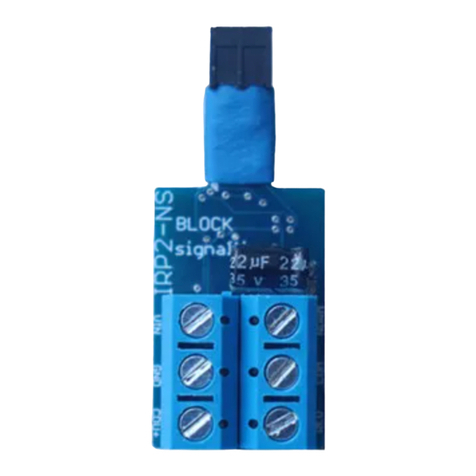
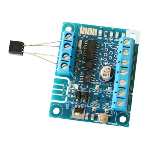
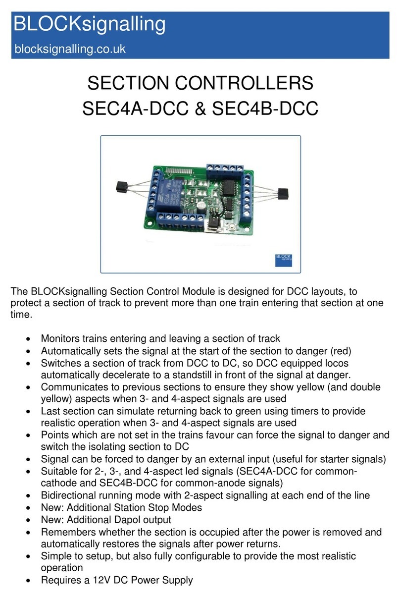
BLOCKsignalling SEC1A-DCC User manual

SECTION CONTROLLERS
SEC1A-DCC & SEC1B-DC
The BLOCKsignalling Section Control Module is designed for DC layouts, to protect
a section of track to prevent more than one train entering that section at one time.
Monitors trains entering and leaving a section of track
Automatically sets the signal at the start of the section to danger (red)
Isolates a section of track to stop trains at the signal
Communicates to previous sections to ensure they show yellow (and
double yellow) aspects when 3- and 4-aspect signals are used
Last section can simulate returning back to clear using timers to provide
realistic operation when 3- and 4-aspect signals are used
Points which are not set in the train’s favour can force the signal to danger
Signal can be forced to danger by an external input (useful for starter
signals)
Suitable for 2-, 3-, and 4-aspect led signals (SEC1A-DC for common-
cathode and SEC1B-DC for common-anode).
Bidirectional running with 2-aspect signalling at each end of the line
New: Additional Station Stop Modes
New: Additional Dapol output
Remembers whether the section is occupied after the power is removed
and automatically restores the signals after power returns.
Simple to setup, but also fully configurable to provide the most realistic
operation
Requires a 12V DC Power Supply

Page 2 of 42
BLOCKsignalling www.blocksignalling.co.uk
Introduction
The BLOCKsignalling Section Control Module is designed to protect a section of
track to prevent more than one train entering that section at one time (see later for
details of the Station Stop Modes).
At the entrance to the section there is a signal and a short isolated piece of track
which can be energised and de-energised by a relay built-in to the module. There is
also an infra-red sensor which is located below the track which is able to detect
trains passing the signal.
The isolated section of track is normally powered via the relay and the signal
normally shows a green aspect.
At the start of the section, the infra-red sensor is continuously looking for a trains
passing, and as soon as it detects one, it switches the signal to red and disconnects
the power from the isolated section of track, stopping any approaching train in front
of the red signal (see later for bidirectional running).
The module then uses a second infra-red sensor located at the exit from the section
of track to detect when the train has completely left the section.
When this is confirmed, the signal at the entrance to the block is switched from
danger back to green (if a 2-aspect signal is used). The isolated track section at the
entrance is also re-energised and any waiting train will then move away past the
signal.
If 3- or 4-aspect signals are connected, then information from the following blocks is
used to switch the signals to show yellow or double yellow. The interconnection
between the modules carries coded information of the status of the block ahead.
In 2-aspect mode, a Dapol signal can be driven via a relay connected to CH5 for
some of the modes (2, 7 and 8). There are also station stop modes. These are
discussed in further detail later.
Bidirectional Running
There are two programs for bi-directional running with 2-aspect signals.
The first uses both sensors to detect trains entering the section. When a train
enters, the signal outputs are set to red. The sensors are checked alternately.
When the train has completely entered, the module then begins checking both
sensors to see if a train leaves the section.

Page 3 of 42
BLOCKsignalling www.blocksignalling.co.uk
The sensors are checked alternately, and if a train is detected, the module waits until
the train has cleared that sensor before setting the signals to green.
The second mode for bi-directional running uses both sensors to detect trains
entering the section. When a train enters, the signal outputs are set to red. The
sensors are checked alternately.
The module remembers the entry sensor and then begins checking the other sensor
to see if a train leaves the section.
If a train is detected leaving via the exit sensor, the module waits until the train has
cleared that sensor before setting the signals to green.
In these two modes, the isolated track sections are not used.
Power-Off Memory
There is a new setting to record whether there was a train in the section at the time
the power is turned off. When the power it turned on again, the information will be
reloaded from memory and so the correct status will be indicated on the signals and
relayed to any interconnected modules.
This feature is also used to remember the directional train are running when the
bidirectional mode is used.
This feature is disabled by default.

Page 4 of 42
BLOCKsignalling www.blocksignalling.co.uk
Module Connections
The diagram below shows the connections to the module.
Terminals
Function
ACIN/+, ACIN/-
Power supply input
S
Track suppression connection (not used)
NC
Relay contact: Normally Closed
COM
Relay contact: Common
NO
Relay contact: Normally Open
SIG+,GND
Connection to previous block for interlocking (note 1)
A1,K1,C1,E1
Sensor 1 connections
CH1-CH5,VOUT
Connections for led signals
A2,K2,C2,E2
Sensor 2 connections
A+,K-
Connection to next block for interlocking (note 2)
Note 1: the connection between the modules carries coded information about the
presence of trains in this section (and following sections if appropriate). This
information is used to switch the yellow aspects on the signals (3- and 4-aspect
only).
Note 2: Optionally connecting steady 12V DC to this input, tells the module the next
section is occupied.
BLOCK
signalling
CH3
CH2
CH1
VOUT
COM
NO
S
NC
AC/IN+
AC/IN-
A2
K2
C2
E2
A+
K-
SENSOR 2
CONNECTIONS
LED SIGNAL
CONNECTIONS
SUPPLY
RELAY
CONTACTS
www.blocksignalling.co.uk
CH5
CH5
A1
K1
C1
E1
SIG+
GND
SENSOR 1
CONNECTIONS
IN FROM
NEXT BLOCK
OUT TO
PREVIOUS BLOCK
POWER
TRACK
SUPRESSOR

Page 5 of 42
BLOCKsignalling www.blocksignalling.co.uk
Power Supply
The controller is designed for use with a 12V DC plug-top type power supply.
The current consumption is 0.25A, and a power supply rated at 0.5A to 1A is
recommended.
Do not connect to the auxiliary terminals on the back of a train controller as the
module may operate unpredictably and could be damaged. These outputs are often
unsuitable as they are designated as a fairly basic power outputs for accessories
such as points motors and may not be smooth or stable.
If a DC power supply is connected with incorrect polarity no damage will occur, but
the module will not operate.

Page 6 of 42
BLOCKsignalling www.blocksignalling.co.uk
Connection for a Single Block
The control of one block section consists of the following parts:
1. An entry sensor, to detect a train entering the section (Sensor 1).
2. An exit sensor, to detect a train leaving the section (sensor 2).
3. A section of isolated track preceding the signal (there are track breaks in only the
right-hand rail), which is controlled by a relay on the block controller stop a train at
the signal when the signal is at danger (this is not used with bidirectional running).
4. Connections to and from adjacent sections to communicate information about
which blocks are occupied (not required when 2-aspect signals are used).
The following diagram shows the connections when 2-aspect signals are used.
BLOCK
signalling
POWER
SUPPLY
DC CONTROLLER
ENTRY SENSOR
(SENSOR 1)
TRACK
BREAK
ISOLATED SECTION
(RIGHT RAIL ONLY)
TRACK
BREAK EXIT SENSOR
(SENSOR 2)

Page 7 of 42
BLOCKsignalling www.blocksignalling.co.uk
2-Aspect signals (Unidirectional Running)
If trains only run in one direction on the line, an isolated section can be placed
preceding the signals. When a train is detected entering the section, the module will
operate the signal and isolate the track section to stop any following trains entering
the same section.
BLOCK
signalling
POWER
SUPPLY
DC CONTROLLER
ENTRY SENSOR
(SENSOR 1)
TRACK
BREAK
ISOLATED SECTION
(RIGHT RAIL ONLY)
TRACK
BREAK EXIT SENSOR
(SENSOR 2)

Page 8 of 42
BLOCKsignalling www.blocksignalling.co.uk
2-Aspect signals (Bi-directional Running)
If bidirectional running is being used with 2-aspect signals, then both the signals are
controlled by one module.
An isolated track section is not used and the module does not stop trains in this
mode.
BLOCK
signalling
POWER
SUPPLY
DC CONTROLLER
ENTRY SENSOR
(SENSOR 1) ENTRY SENSOR
(SENSOR 2)

Page 9 of 42
BLOCKsignalling www.blocksignalling.co.uk
Connection Multiple Simple Blocks
When 2-aspect signals are used, there are no interconnections between adjacent
sections.
If 3- or 4-aspect signals are used, additional connections are required between the
modules to communicate which sections in front of the train are occupied (otherwise
yellow signal aspects will not be shown).
To connect blocks together, the Train in Section (TIS) wiring is linked from one block
to the next.

Page 10 of 42
BLOCKsignalling www.blocksignalling.co.uk
2 Aspect Led Signal Example
In the following example, 2 aspect led signals are used and the diagram has been
simplified to show only the relevant wiring. The train has driven from the left to the
right, and is currently in Block 3.
The block section controller for Block 3 has detected the train enter the section, and
has set the signal to danger (red) and isolated the track section to prevent any other
trains entering.
There is no need to connect the sections together as with 2-aspect signalling, the
signal preceding a section only shows the occupancy of the section itself.
If there are points in use, we can feed 12V into the train in section inputs via the
points auxiliary contacts, and this will force one of the associated signals to red.
SEC SEC
TRAIN DIRECTION
SEC
BLOCK 1 BLOCK 2 BLOCK 3
BLOCK
signalling
TRAIN
TRACK SECTION
ISOLATED
BLOCK SECTION
CONTROLLER BLOCK SECTION
CONTROLLER
TRAIN DIRECTION
BLOCK SECTION
CONTROLLER
BLOCK SECTION
CONTROLLER
BLOCK 1 BLOCK 2 BLOCK 3
BLOCK 4
BLOCK
signalling
+12V
TRAIN
TRACK SECTION
ISOLATED
0V
TRACK SECTION
ISOLATED

Page 11 of 42
BLOCKsignalling www.blocksignalling.co.uk
3 Aspect Led Signal Example
In the following example, 3 aspect signals are used. The train has driven from the
left to the right, and is currently in Block 3.
The block section controller for Block 3 has detected the train enter the section, and
has set the signal to danger (red) and isolated the track section to prevent any other
trains entering.
The Block 3 controller signals to the preceding Block 2 controller that it is at danger
(red) and so the Block 2 controller indicates caution (yellow). It does this by sending
a coded message on the train in section wiring.
The Block 1 controller doesn’t receive any message on the train in section wiring, so
shows a green signal.
If there are points in use, we switch a feed to the train in section inputs via the points
auxiliary contacts, and this will force one of the associated signals to red.
We also need to make sure the signal from the following section gets to the two
preceding sections, which we do via diodes to separate the points switch from the
output of the section controller which is sending coded messages about the
presence of the train.
The connections for the SEC1A are shown below.
SEC
TRAIN DIRECTION
SEC
BLOCK 1 BLOCK 2 BLOCK 3
BLOCK
signalling
SEC
TRAIN
TRACK SECTION
ISOLATED
SEC SEC
TRAIN DIRECTION
SEC
SEC
BLOCK 1 BLOCK 2
BLOCK 3
BLOCK 4
BLOCK
signalling
DIODES ARE GENERAL
PURPOSE 1N001-1N004
TRAIN
TRACK SECTION
ISOLATED
+12V
GND
SEC1A

Page 12 of 42
BLOCKsignalling www.blocksignalling.co.uk
The wiring for the SEC1B is slightly different and shown in the following diagram.
You can think of the points switch overriding the message from the following section
controller, and forcing one route to red as the points are not in their favour.
SEC SEC
TRAIN DIRECTION
SEC
SEC
BLOCK 1 BLOCK 2
BLOCK 3
BLOCK 4
BLOCK
signalling
DIODES ARE GENERAL
PURPOSE 1N001-1N004
TRAIN
TRACK SECTION
ISOLATED
+12V
GND
SEC1B

Page 13 of 42
BLOCKsignalling www.blocksignalling.co.uk
4 Aspect led Light Signal Example
In the following example, 4 aspect light signals are used. The train has driven from
the left to the right, and is currently in Block 3.
The block section controller for Block 3 has detected the train enter the section, and
has set the signal to danger (red) and isolates the track section to prevent any other
trains entering.
The Block 3 controller signals that it is at danger to the preceding Block 2 controller
and so the Block 2 controller indicates caution (yellow).
The Block 2 controller signals that it is at caution to the preceding Block 1 controller
and so the Block 1 controller indicates distant caution (double yellow).
The preceding controller (not shown) doesn’t receive any message on the train in
section wiring, so shows a green signal.
If there are points in use, we switch a feed to the train in section inputs via the points
auxiliary contacts, and this will force one of the associated signals to red.
We also need to make sure the signal from the following section gets to the two
preceding sections, which we do via diodes to separate the points switch from the
output of the section controller which is sending coded messages about the
presence of the train.
SEC
TRAIN DIRECTION
SEC
BLOCK 1 BLOCK 2
BLOCK 3
BLOCK
signalling
TRAIN
TRACK SECTION
ISOLATED
SEC

Page 14 of 42
BLOCKsignalling www.blocksignalling.co.uk
The connections for the SEC1A are shown below.
The wiring for the SEC1B is slightly different and shown in the following diagram.
You can think of the points switch overriding the message from the following section
controller, and forcing one route to red as the points are not in their favour.
SEC SEC
TRAIN DIRECTION
SEC
SEC
BLOCK 1 BLOCK 2
BLOCK 3
BLOCK 4
BLOCK
signalling
DIODES ARE GENERAL
PURPOSE 1N001-1N004
TRAIN
TRACK SECTION
ISOLATED
+12V
GND
SEC1A
SEC SEC
TRAIN DIRECTION
SEC
SEC
BLOCK 1 BLOCK 2
BLOCK 3
BLOCK 4
BLOCK
signalling
DIODES ARE GENERAL
PURPOSE 1N001-1N004
TRAIN
TRACK SECTION
ISOLATED
+12V
GND
SEC1B

Page 15 of 42
BLOCKsignalling www.blocksignalling.co.uk
Configuration for Ends of Track and Points
At the start of a section of track, there are no preceding sections which are signalled,
so the connections of the module do not need to be connected to any preceding
blocks.
At the end of a section of track there are no following sections which are signalled,
so the connections of the module do not need to be connected to any following
blocks. When the train leaves the final block, the connected signal will switch from
red straight back to green.
As an option, these final blocks can be set to revert from red to green (via yellow and
double yellow if appropriate) by setting timers. For instance, a train can disappear
into a tunnel, and after a time, the signal will switch back through the sequence to
green automatically to give the most realistic operation.
The final module needs to be programmed to act using timers using memory 3 (see
later) and sensor 1 and sensor 2 need to be installed as normal.
Using auxiliary contacts from points motors, a 12V DC feed can be connected to the
A+, K- inputs of a module. A constant +12V DC will force the module to show a
danger signal and switch DC to a track section, protecting points which are not set in
a train's favour.

Page 16 of 42
BLOCKsignalling www.blocksignalling.co.uk
Programming Procedure
Many of the settings on the module are adjustable (although for most users it is only
necessary to set whether 2-, 3- or 4-aspect signalling is used).
Programming is performed by inserting a link between the A and K terminals and
holding down the Push Button when switching on the power (this link will be removed
shortly and the infra-red sensor connected). The module can also be programmed
whilst the infra-red sensors are connected.
Full details of the programming procedure is given later in the document.

Page 17 of 42
BLOCKsignalling www.blocksignalling.co.uk
Connecting the Infra-Red Sensors
An Infra-Red source and Infra-Red detector are moulded into a single 5mm x 6.5mm
package that can be located below the track bed to reflect light off rolling stock.
The wires can be extended using small chocolate block and extra lengths of cable if
required (not supplied).
BLOCK
signalling
SENSOR REAR VIEW
EMITTERDETECTOR
MOULDING
CHAMFER
C
E K
ACONNECT TO ACONNECT TO C
CONNECT E CONNECT TO K
A
K
CE
Clear Lens
Grey Lens

Page 18 of 42
BLOCKsignalling www.blocksignalling.co.uk
Sensitivity Setting
The module is supplied with the sensitivity pre-set to suit most installations and
should not need adjustment.
In locations such as tunnels, or when the module is not being used under the track
bed, then it may be desirable to adjust the detection threshold.
The sensitivity is factory set to 5, and can be adjusted from 1 to 10 (with 1 being the
most sensitive and 10 being the least sensitive).
To change the sensitivity, switch off the power to the module and hold down the
Push Button. Apply the power and continue holding the Push Button until 9 flashes
of the led are seen. At this point, release the button. You will see a long flash of five
seconds.
The led will begin flashing again. When you have reached the desired number of
flashes to set the new sensitivity, press the button. You will see a long flash of five
seconds and then 10 rapid flashes. The programming is then complete and the
module will restart. If you make a mistake programming, simply repeat the process.
Performing a factory reset will reset the sensitivity setting back to 5.

Page 19 of 42
BLOCKsignalling www.blocksignalling.co.uk
Installation
The Infra-Red sensor is normally installed below the track-bed. The detection range
of the unit is up to approximately 25mm from the face of the package when normal
sensitivity is set (for dark surfaces with low levels of reflectivity).
The detector can be mounted in an 8mm hole drilled through the track baseboard. If
required, the detector can be held in place using a small amount of blutack,
expanded polystyrene or similar.
The led diameter is 2.2mm, so on smaller scales the leds can still have a clear view
between the sleepers.
BLOCK
signalling
Sensors Mounted
Through Baseboard
Isolated Section
(Length as required)
Track Break
Signal Position
(after track break)
Entry Sensor
Position
Minimum > Loco Length
Exit Sensor
Position
Position entry sensor at least one loco length past the
track break.
Position exit sensor so the whole train can leave the
section and so clear the sensor successfully.

Page 20 of 42
BLOCKsignalling www.blocksignalling.co.uk
This manual suits for next models
1
Table of contents
Other BLOCKsignalling Controllers manuals
Popular Controllers manuals by other brands
Action Clima
Action Clima CR26 Use, Installation, Technical Manual

dSPACE
dSPACE DS1103 Hardware Installation and Configuration
Aprilaire
Aprilaire 56 Safety and installation instructions
RadioLink
RadioLink BYME-A instruction manual
Robo-Tank
Robo-Tank Basic user manual
MSA
MSA FireHawk M7 Maintenance and Repair
FRC
FRC RTU1-IS operating instructions
NXP Semiconductors
NXP Semiconductors PN7150 Hardware Design Guide
Atlas
Atlas BlueBridge BBWP Series installation guide
BFT
BFT IGEA LB Installation and user manual

SEW-Eurodrive
SEW-Eurodrive DR63 Series Addendum to the Operation Instructions
AccuTherm
AccuTherm U-8226S-ACCU1 instruction manual
