1
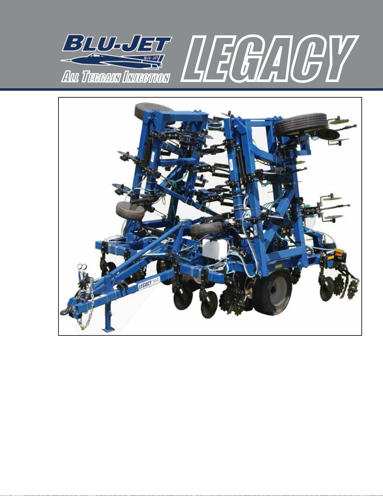
LEGACY
Table of Contents Introduction------------------------------------------------------------------------------------------------------- 1
Deliver--------------------------------------------------------------------------------------------------------------- 4
To The Owner----------------------------------------------------------------------------------------------------- 5
Warranty------------------------------------------------------------------------------------------------------------ 6
Safety--------------------------------------------------------------------------------------------------------------- 7
Operating Instructions---------------------------------------------------------------------------------------- 11
Anhydrous Ammonia Operating Instructions--------------------------------------------------------- 19
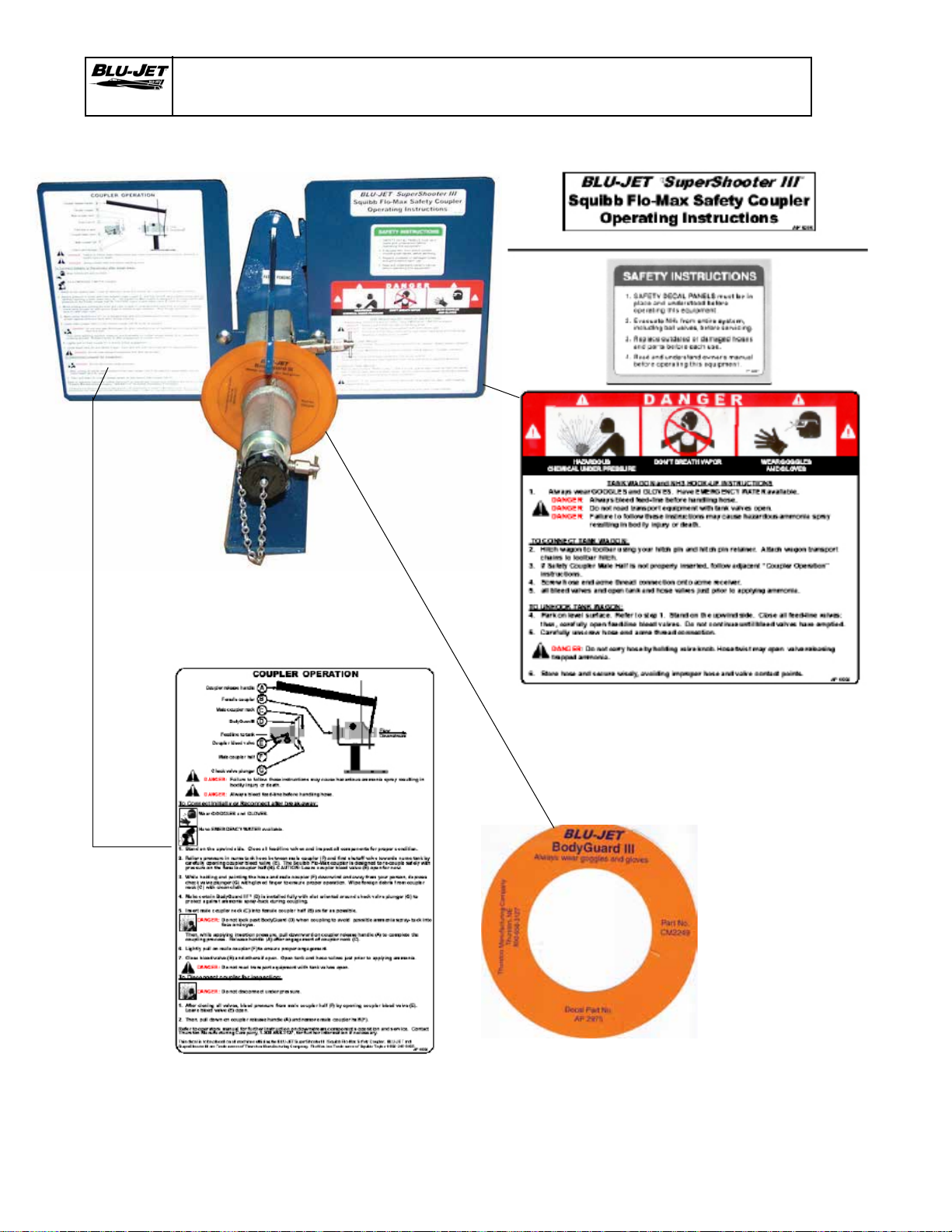
Coupler Operation---------------------------------------------------------------------------------------------- 22
Parts----------------------------------------------------------------------------------------------------------------- 23
Emergency Fresh Water Tank--------------------------------------------------------------------------------- 23
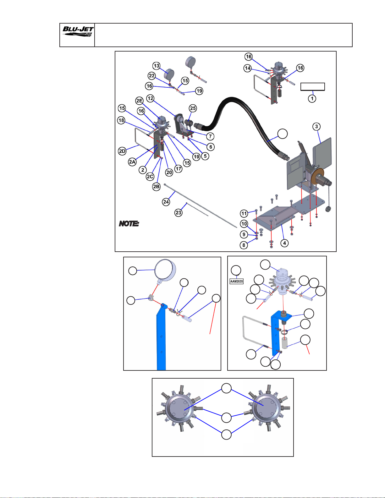
Main Frame-------------------------------------------------------------------------------------------------------- 24
Primary Wing Right-hand--------------------------------------------------------------------------------------- 26
Primary Wing Left-hand----------------------------------------------------------------------------------------- 28
Secondary Wing Right-hand----------------------------------------------------------------------------------- 30
Secondary Wing Left-hand------------------------------------------------------------------------------------- 32
Secondary Wing Right-hand 3’-2”---------------------------------------------------------------------------- 34
Secondary Wing Left-hand 3’-2”------------------------------------------------------------------------------ 35
Dual Wheel Lift---------------------------------------------------------------------------------------------------- 36
Single Wheel Lift-------------------------------------------------------------------------------------------------- 38
Tongue--------------------------------------------------------------------------------------------------------------- 40
Secondary Wing Stop and Straight Extension------------------------------------------------------------ 42
Secondary Wing Extension To 50 ft.-------------------------------------------------------------------------- 43
Pin Adjust Gauge Wheel---------------------------------------------------------------------------------------- 44
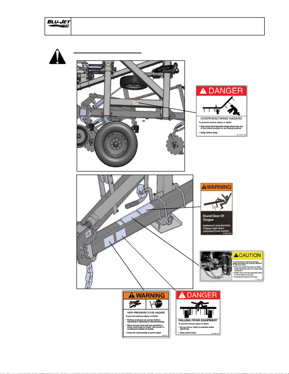
Decals--------------------------------------------------------------------------------------------------------------- 45
Legacy 38’, 42’, 47’, 52’ Toolbars----------------------------------------------------------------------------- 46
Legacy Hydraulics 38’, 42’, And 47’--------------------------------------------------------------------------- 48
Hose Kit 38’, 42’, And 47’---------------------------------------------------------------------------------------- 52
Legacy Hydraulics 52’-------------------------------------------------------------------------------------------- 54
Hose Kit 52’--------------------------------------------------------------------------------------------------------- 57
Stagger Brackets Offset 6 x 6 Mounting-------------------------------------------------------------------- 60
Coulter, Super 1200 Flex and Shank------------------------------------------------------------------------ 62
Nurse Tank Hitch PKG00234---------------------------------------------------------------------------------- 63
Nurse Tank Hitch PKG00247 Low Mounting--------------------------------------------------------------- 64
Auto-Lok Nurse Tank Hitch AAM2870----------------------------------------------------------------------- 65
Blades--------------------------------------------------------------------------------------------------------------- 66
SealPro II and SealPro SKF----------------------------------------------------------------------------------- 67
Hitches--------------------------------------------------------------------------------------------------------------- 74
Jack------------------------------------------------------------------------------------------------------------------ 75
Shanks-------------------------------------------------------------------------------------------------------------- 76
Row Clamps------------------------------------------------------------------------------------------------------- 77
Manual Holder----------------------------------------------------------------------------------------------------- 80
Impellicone Mounting Hardware------------------------------------------------------------------------------ 81
SuperShooter III--------------------------------------------------------------------------------------------------- 82
SuperShooter III Single Assembly Less Distribution (66000136)------------------------------------- 83
SuperShooter III Add-on Dual Assembly Less Distribution (66000137)---------------------------- 84
GDI W/Pump Distribution (Rear Mount) (Bundle 20200119)------------------------------------------ 88
GDI W/Twin Pump Distribution (Rear Mount) (Bundle 20200121)----------------------------------- 96
Dual Impellicone Manifold Distribution Bundles---------------------------------------------------------- 105
MaxPac AR700 Parts and Assembly------------------------------------------------------------------------ 113
MaxPac Basket Mount Arm------------------------------------------------------------------------------------ 114
Coulter Extension Kit (9-7/8”)----------------------------------------------------------------------------------- 115
MaxPac Assembly------------------------------------------------------------------------------------------------- 116
Torsion Arm Basket Parts and Assembly------------------------------------------------------------------- 118
Torsion Arm Basket Flat Mounting---------------------------------------------------------------------------- 121
Residue Managers Parts and Assembly-------------------------------------------------------------------- 122
Light Kit/SMV------------------------------------------------------------------------------------------------------ 130
GDI Lift Kit---------------------------------------------------------------------------------------------------------- 132
Hub and Spindle Assembly------------------------------------------------------------------------------------- 133
Hydraulic Repair Kit---------------------------------------------------------------------------------------------- 136
Tie-rod Cylinder Disassembly-Assembly Procedure----------------------------------------------------- 137
Torque Specications-------------------------------------------------------------------------------------------- 138
Specications------------------------------------------------------------------------------------------------------ 139
Assembly................................................................................................................................ 141
Main Frame and Primary Wings------------------------------------------------------------------------------ 141
Secondary Wings------------------------------------------------------------------------------------------------- 142
Dual Wheel Lift---------------------------------------------------------------------------------------------------- 143
Single Wheel Lift-------------------------------------------------------------------------------------------------- 146
Primary Wing Gauge Wheel------------------------------------------------------------------------------------ 148
Center Section Wheel Lift Linkage--------------------------------------------------------------------------- 152
Tongue Mounting------------------------------------------------------------------------------------------------- 155
Tongue Linkage--------------------------------------------------------------------------------------------------- 156
Bolt-on Cylinder Lug--------------------------------------------------------------------------------------------- 159
Primary Wing Cable Release---------------------------------------------------------------------------------- 160
Hitch and Safety Chain------------------------------------------------------------------------------------------ 161
Jack------------------------------------------------------------------------------------------------------------------ 162
Hose Holder and Hose Tender-------------------------------------------------------------------------------- 163
Turnbuckle Wrench----------------------------------------------------------------------------------------------- 164
Hitch Storage------------------------------------------------------------------------------------------------------ 165
Manual Holder----------------------------------------------------------------------------------------------------- 166
Stagger Brackets-------------------------------------------------------------------------------------------------- 167
Primary Wing Linkage------------------------------------------------------------------------------------------- 168
Secondary Wing Linkage--------------------------------------------------------------------------------------- 169
Secondary Wing Latch Standard Wing---------------------------------------------------------------------- 170
Secondary Wing 28” Extension Kit---------------------------------------------------------------------------- 171
Secondary Wing Angled Stagger------------------------------------------------------------------------------ 172
Hose Holder Placement----------------------------------------------------------------------------------------- 173
Hydraulics 52’------------------------------------------------------------------------------------------------------ 174
Hydraulics 38’, 42”, 47’------------------------------------------------------------------------------------------ 185
Pin Adjust Gauge Wheel---------------------------------------------------------------------------------------- 197
Nurse Tank Hitch Single PKG00234------------------------------------------------------------------------- 198
Nurse Tank Hitch Single Low Mounting PKG00247------------------------------------------------------ 200
SuperShooter III Add-on Parts (66000136)---------------------------------------------------------------- 202
SuperShooter III Add-on Parts, Dual (66000137)--------------------------------------------------------- 206
Coulter--------------------------------------------------------------------------------------------------------------- 210
Shank---------------------------------------------------------------------------------------------------------------- 212
Spring Cushion---------------------------------------------------------------------------------------------------- 214
Light Kit-------------------------------------------------------------------------------------------------------------- 216
SMV------------------------------------------------------------------------------------------------------------------ 220
Safety Tank--------------------------------------------------------------------------------------------------------- 221
Depth Collars------------------------------------------------------------------------------------------------------ 222
Decals--------------------------------------------------------------------------------------------------------------- 223
Hydraulic System Charging------------------------------------------------------------------------------------ 225
Folding Toolbar--------------------------------------------------------------------------------------------------- 226
Depth Control (66000148)------------------------------------------------------------------------------------- 227
Row Spacing Layout------------------------------------------------------------------------------------------- 237
Manual Number:
0605010
Rev. 2-19-18