BLU-JET AT6020 User manual

Manual Number
0606020
Rev. 2-19-18 $20.00 Net.
Assembly
and Operators
Manual
TM
AT6020
Commercial Fertilizer Injection Applicator

Thurston Manufacturing Company •1708 H Ave •Box 218 • Thurston, Nebraska, 68062-0218
Design specications and features as described are subject to change without notice. BLU-JET is a registered trademark of Thurston Manufacturing Company, Thurston NE.
/BLU-JET @BLU-JET01 /SIronWorks @SIronWorks

1
AT6020
Table of Contents Introduction------------------------------------------------------------------------------------------------------- 1
Deliver--------------------------------------------------------------------------------------------------------------- 4
To The Owner----------------------------------------------------------------------------------------------------- 5
Warranty------------------------------------------------------------------------------------------------------------ 6
Safety--------------------------------------------------------------------------------------------------------------- 7
Operating Instructions---------------------------------------------------------------------------------------- 11
Anhydrous Ammonia Operating Instructions--------------------------------------------------------- 19
Coupler Operation---------------------------------------------------------------------------------------------- 22
Parts----------------------------------------------------------------------------------------------------------------- 23
Emergency Fresh Water Tank--------------------------------------------------------------------------------- 23
Operational Guide For Various Residue Situations BLU-JET StripTill Implement--------------- 24
Center Section Bundle 66000103 Parts List--------------------------------------------------------------- 35
Primary Wing Right-hand Bundle 66000103--------------------------------------------------------------- 40
Primary Wing Left-hand Bundle 66000103----------------------------------------------------------------- 42
Center Section Bundle 66000103 Exploded Views------------------------------------------------------- 44
Center Section Bundle 66000103 Depth Control Parts-------------------------------------------------- 48
Secondary Wing Right-hand With Hydraulic Gauge Wheel Bundle 66000107-------------------- 50
Secondary Wing Left-hand With Hydraulic Gauge Wheel Bundle 66000107---------------------- 52
Dual Wheel Lift Bundle 66000105---------------------------------------------------------------------------- 54
Pin Adjust Gauge Wheel Bundle 55000100---------------------------------------------------------------- 56
48’ and 60’ Complete Toolbar Drawings--------------------------------------------------------------------- 57
Hydraulics 60’------------------------------------------------------------------------------------------------------ 58
Hydraulics 48’------------------------------------------------------------------------------------------------------ 63
Third Wing Bundle 66000108 Left Side--------------------------------------------------------------------- 70
Third Wing Bundle 66000108 Right Side------------------------------------------------------------------- 72
Stagger Brackets Offset 6 x 6 Mounting-------------------------------------------------------------------- 74
Stagger Bracket 40 x 48 Double, (AAM2125)------------------------------------------------------------- 75
Offset Stagger Bracket (AAM2136)-------------------------------------------------------------------------- 76
Super 1200 Flex Coulter and Shank------------------------------------------------------------------------- 77
Nurse Tank Hitch Assembly PKG00234--------------------------------------------------------------------- 78
Nurse Tank Hitch Assembly, Low Mounting PKG00247------------------------------------------------- 79
Auto-Lok Nurse Tank Hitch (AAM2831)-------------------------------------------------------------------- 80
Blades---------------------------------------------------------------------------------------------------------------- 82
SealPro ll and SealPro SKF------------------------------------------------------------------------------------ 83
Hitches--------------------------------------------------------------------------------------------------------------- 90
Jack------------------------------------------------------------------------------------------------------------------ 91
Shanks-------------------------------------------------------------------------------------------------------------- 92
Row Clamps------------------------------------------------------------------------------------------------------- 93
Manual Holder----------------------------------------------------------------------------------------------------- 96
Impellicone Mounting Hardware------------------------------------------------------------------------------ 97
SuperShooter------------------------------------------------------------------------------------------------------ 98
SuperShooter III Add-on Parts (66000136) Single Assembly------------------------------------------ 100
SuperShooter III Add-on Parts (66000137) Dual Assembly------------------------------------------- 102
GDI With Pump Distribution (Rear Mount) (Bundle 20200119)---------------------------------------- 104
Heat Exchanger (CCP2755)----------------------------------------------------------------------------------- 107
GDI WithTwin Pump Distribution (Rear Mount)(Bundle 20200121)---------------------------------- 112
Meter Assembly Impellicone Manifolds--------------------------------------------------------------------- 121
MaxPac AR700 Parts and Assembly------------------------------------------------------------------------ 131
MaxPac Basket Mount Arm------------------------------------------------------------------------------------ 132
Coulter Extension Kit (9-7/8”)----------------------------------------------------------------------------------- 133
MaxPac Assembly------------------------------------------------------------------------------------------------- 134
Torsion Arm Basket Parts---------------------------------------------------------------------------------------- 136
Torsion Arm Assembly-------------------------------------------------------------------------------------------- 137
Torsion Arm Mounting Bracket Rigid Fertilizer Row------------------------------------------------------ 138
Basket Mount Flat With Hardware---------------------------------------------------------------------------- 139
Decals---------------------------------------------------------------------------------------------------------------- 140
StripTill Residue Manager Parts------------------------------------------------------------------------------- 141
Coulter Shank Extensions Brackets-------------------------------------------------------------------------- 142
StripTill Residue Manager Assembly------------------------------------------------------------------------- 143
Light Kit/Slow Moving Vehicle--------------------------------------------------------------------------------- 149
Light Kit/Slow Moving Vehicle 20” Row Spacing---------------------------------------------------------- 151
GDI Lift Kit---------------------------------------------------------------------------------------------------------- 153
Hub and Spindle Assembly------------------------------------------------------------------------------------- 154
Hydraulic Repair Kit---------------------------------------------------------------------------------------------- 160
Tie-rod Cylinder Disassembly-Assembly Procedure----------------------------------------------------- 161
Torque Specications-------------------------------------------------------------------------------------------- 162
Specications------------------------------------------------------------------------------------------------------ 163
Assembly................................................................................................................................ 165
Main Frame and Primary Wings------------------------------------------------------------------------------ 165
Secondary Wings------------------------------------------------------------------------------------------------- 166
Dual Wheel Lift----------------------------------------------------------------------------------------------------- 168
Primary Wing Gauge Wheels----------------------------------------------------------------------------------- 171
Center Section Wheel Lift Linkage--------------------------------------------------------------------------- 175
Tongue Mounting------------------------------------------------------------------------------------------------- 177
Tongue Linkage--------------------------------------------------------------------------------------------------- 178
Bolt-on Cylinder Lug--------------------------------------------------------------------------------------------- 181
Primary Wing Cable Release---------------------------------------------------------------------------------- 182
Hitch and Safety Chain------------------------------------------------------------------------------------------ 183
Jack------------------------------------------------------------------------------------------------------------------ 184
Hose Holder and Hose Tender-------------------------------------------------------------------------------- 185
Turnbuckle Wrench----------------------------------------------------------------------------------------------- 186
Hitch Storage------------------------------------------------------------------------------------------------------ 187
Manual Holder----------------------------------------------------------------------------------------------------- 188
Stagger Brackets-------------------------------------------------------------------------------------------------- 189
Primary Wing Linkage------------------------------------------------------------------------------------------- 190
Secondary Wing Linkage--------------------------------------------------------------------------------------- 191
Third Wing Linkage----------------------------------------------------------------------------------------------- 193
Secondary Wing Latch Standard Wing---------------------------------------------------------------------- 194
Hose Holder Placement 60’------------------------------------------------------------------------------------- 195
Hydraulics 60’ Assembly------------------------------------------------------------------------------------------ 196
Depth Control Parts and Assembly---------------------------------------------------------------------------- 201
Hydraulic Hoses 60’ Assembly--------------------------------------------------------------------------------- 210
Hose Holder Placement 48’------------------------------------------------------------------------------------- 218
Hydraulics 48’ Assembly----------------------------------------------------------------------------------------- 220
Hydraulics Hoses 48’ Assembly------------------------------------------------------------------------------- 222
Nurse Tank Hitch Single PKG00234------------------------------------------------------------------------- 234
Nurse Tank Hitch Single Low Mounting PKG00247------------------------------------------------------ 236
SuperShooter III Add-on Parts (66000136) Single Assembly------------------------------------------ 238
SuperShooter III Add-on Parts (66000137) Dual Assembly------------------------------------------ 242
Swing Adjust Gauge Wheel------------------------------------------------------------------------------------ 246
Coulter--------------------------------------------------------------------------------------------------------------- 247
Shank---------------------------------------------------------------------------------------------------------------- 249
Spring Cushion---------------------------------------------------------------------------------------------------- 251
Light Kit & Slow Moving Vehicle------------------------------------------------------------------------------ 253
Light Kit & Slow Moving Vehicle 20” Row Spacing------------------------------------------------------- 258
Safety Tank--------------------------------------------------------------------------------------------------------- 261
Depth Collars------------------------------------------------------------------------------------------------------ 262
Decals--------------------------------------------------------------------------------------------------------------- 263
Hydraulic System Charging------------------------------------------------------------------------------------ 265
Folding Tool Bar--------------------------------------------------------------------------------------------------- 266
Row Spacing Layout------------------------------------------------------------------------------------------- 267
Manual Number:
0606020
Rev. 2-19-18

2
AT6020
Welcome to Thurston Manufacturing Company. Our goal is to provide
quality products and services to our customers. The company’s BLU-JET
products have a reputation for quality, excellence in design and proven
durability. Energetic, resourceful and continuous improvement goals in
Environmental, Safety, Quality, Production and Engineering keep our
rm at the cutting edge of technology.
We hope your BLU-JET equipment will give you years of service.
Introduction
Read this manual carefully. It will instruct you on how to operate and
service your machine safely and correctly. Failure to do so could result
in personal injury and/or equipment damage.
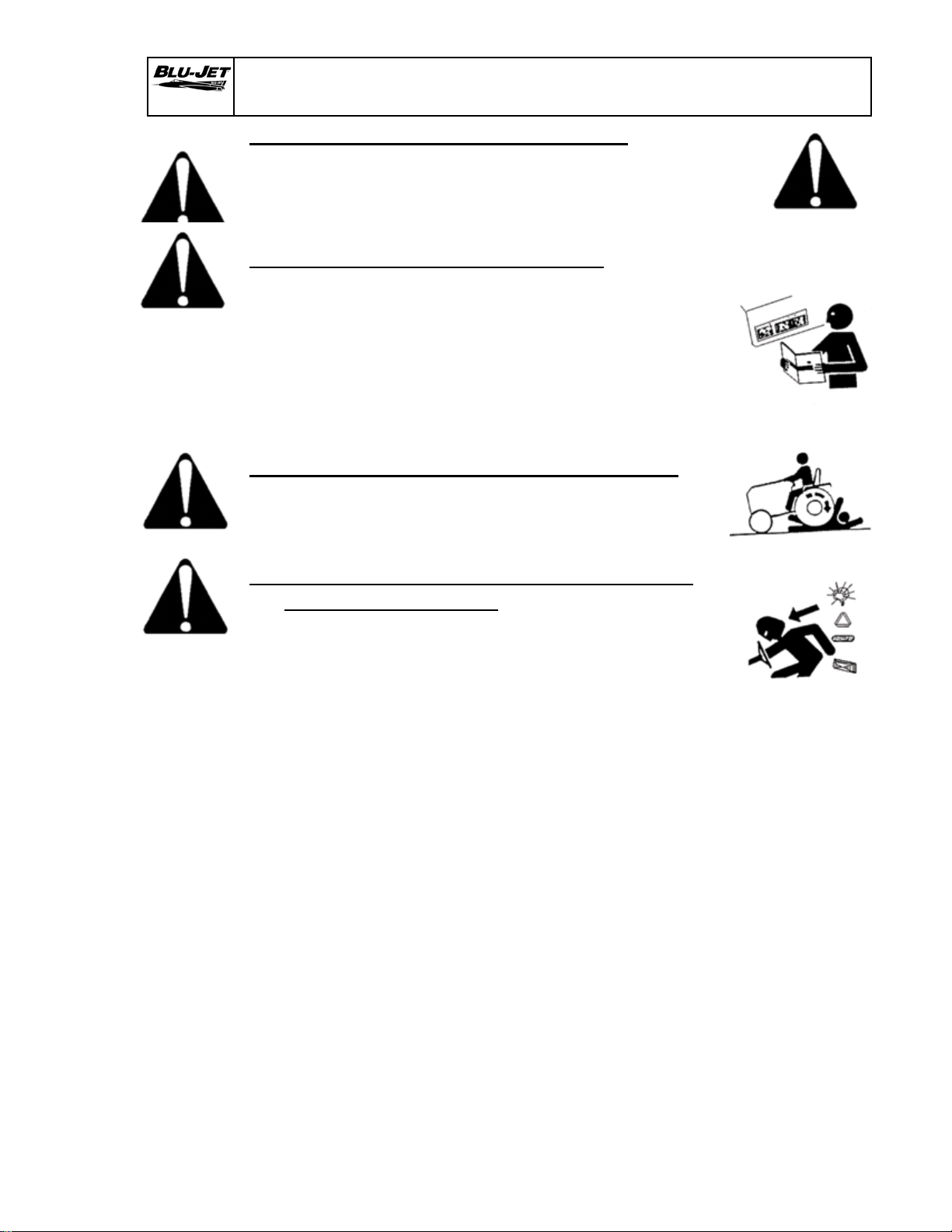
SAFETY INFORMATION
Indicates an imminently hazardous situation that, if
not avoided, will result in death or serious injury.
The sign will have the color combination of red and
white.
Indicates a potentially hazardous situation that, if
not avoided, could result in death or serious injury.
The sign will have the color combination of orange
and black.
Indicates a potentially hazardous situation that, if
not avoided, may result in minor or moderate injury.
The sign will have the color combination of yellow
and black.
NOTE: Indicates a special point of information.
Carefully read and follow all safety signs. Reinstall safety signs that
are damaged or missing.
Right-hand and left-hand sides of the implement are determined by
facing in the direction the implement will travel when going forward.
DANGER
WARNING
CAUTION
3
AT6020
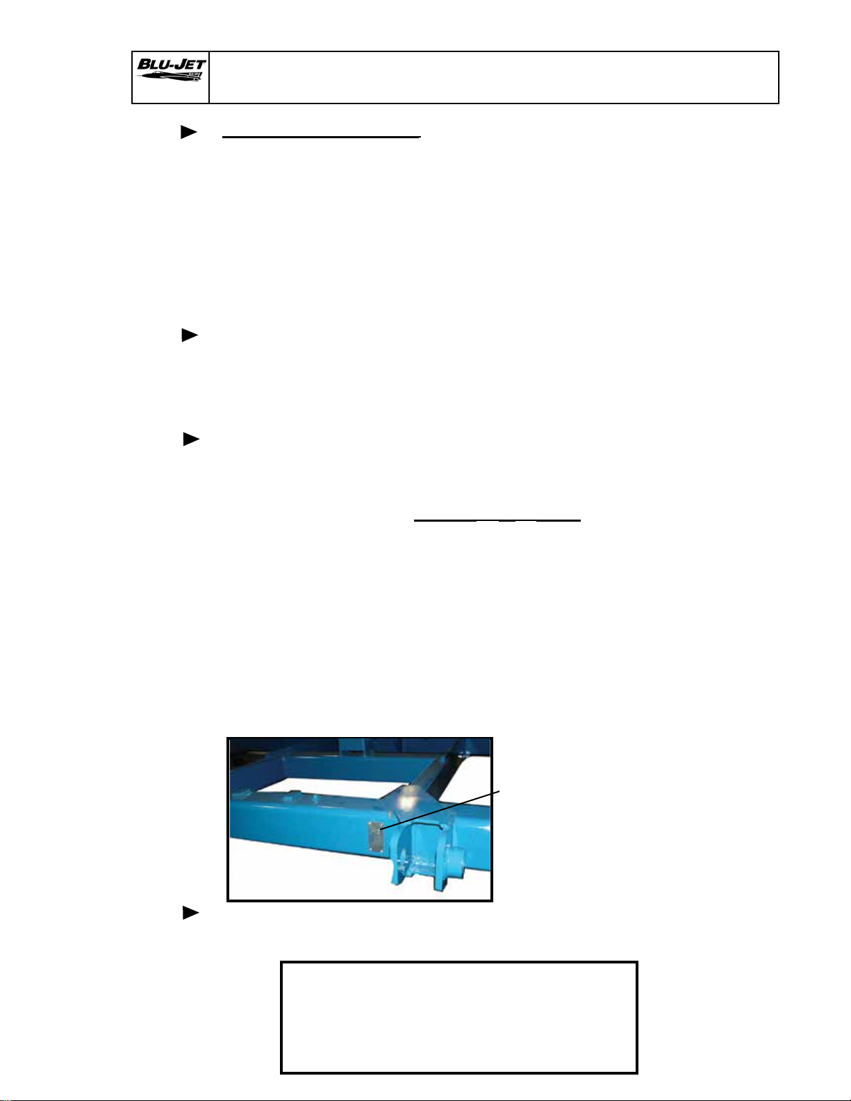
Tractor side
The Serial Number
is located from the
rear of the tool bar
on the right-hand
side behind the
tongue pull plate.
Introduction
For your convenience we have four easy ways to register your warranty.
•Call our toll free number and ask for warranty registration.
1-800-658-3127
•Register on-line at: www.BLU-JET.com
•Complete and mail this Product Registration form to:
Attn: Thurston Manufacturing Company
Product Registration
PO Box 218
Thurston, NE. 68062
• Email a copy to: [email protected]
Thurston Manufacturing Company Warranty does not cover the following:
1) Cleaning, transporting, mailing and service call charges.
2) Depreciation or damage caused by normal wear, accidents,
improper protection or improper use.
MODEL NO.__________________________
SERIAL NO.__________________________
DATE PURCHASED___________________
Record your implement model and serial number in the space provided below.
Your dealer needs this information to give you prompt, efcient service when
you order parts.
General Information:
The BLU-JET AT6020 Commercial Class Fertilizer Injection Applicator
achieves a new performance dimension for high acre, high rate applications.
The BLU-JET AT6020 can easily be congured for a number of operations
including Pre-Plant, Side-Dress, and StripTill applications with anhydrous,
liquid, dry, or dual placement fertilizer injection.
The AT6020 was designed to be used in combination with BLU-JET’s
Super 1200 Coulter, MaxPac 700 AutoReset shank mounting, residue managers,
SealPro disc sealers, torsion arm rming baskets and BLU-JET’s complete
line of shank mountings.
Warranty is provided for customers who operate and maintain their equipment
as described in this manual. Warranty registration is accomplished by
the dealer completing and forwarding the WARRANTY REGISTRATION FORM
to Thurston Manufacturing Company. It is in your best interest to ensure that
this has been done.

4
AT6020
1. All hardware properly tightened
2. Lubrication of grease ttings
3. All decals properly located and readable
4. Other adjustments for machine level height, etc.
5. Overall condition (touch up any scratches, clean and
polish)
6. Operator’s manual
DATE SET UP_______________________________
SIGNATURE________________________________
PRE-DELIVERY CHECKLIST
Dealer Checklist
To The Dealer:
Inspect the implement thoroughly after assembly to be certain it is
functioning properly before delivering it to the customer. The following
checklist is a reminder of points to cover. Check off each item as it is
found satisfactory or after proper adjustment is made.
DELIVERY
Review the operator’s manual with the customer. Explain
the following:
1. Safe operation and service
2. Correct machine installation and operation
3. Daily and periodic lubrication and maintenance
4 Daily and periodic inspections
5. Trouble shooting
6. Storing machine
7. Thurston Manufacturing Company parts and service
8. Have the customer write the machine model and serial
number in space provided in manual introduction.
9. Give customer the operator’s manual and encourage
the customer to read the manual carefully.
10. Completion and mailing of warranty registration
form.
DATE DELIVERED__________________________
SIGNATURE_______________________________
MODEL NO.________________________________
SERIAL NO.________________________________

5
AT6020
To The Owner
Thank you for your recent purchase of a new BLU-JET
implement. The primary objective of Thurston Manufacturing
Company is to build and provide you with a quality product.
However, in the event that a problem does occur, it is imperative
that your warranty registration is on le in order to accurately
respond to your specic service circumstances.
For your convenience we have four easy ways to register
your warranty:
For your convenience we have four easy ways to register your warranty.
•Call our toll free number and ask for warranty registration.
1-800-658-3127
•Register on-line at: www.BLU-JET.com
•Complete and mail this Product Registration form to:
Attn: Thurston Manufacturing Company
Product Registration
PO Box 218
Thurston, NE. 68062
• Email a copy to: [email protected]
This manual has been prepared to assist you in the assembly
of your new machine and contains information pertaining to
safety, operations and all of its parts. Our personnel in sales
and service are always available to assist you when questions
arise concerning the assembly or operations of your tool bar.
When ordering parts, please refer to part numbers and
descriptions as listed throughout this book. All parts and
whole goods will be shipped FOB Thurston, Nebraska. Or
FOB your regional distributor. Always check merchandise
immediately upon receipt for damage or shortage. Note any
discrepancy on carrier’s bill of lading and notify Sender within
10 days. Returned goods will be subject to a 15% restocking
charge. Thurston Manufacturing Company reserves the right
to make improvements and modications on equipment
without obligation to change previously built equipment. All
prices are subject to change without notice.

6
AT6020
Thurston Manufacturing Company warrants each new BLU-JET machine
primary framework to be free from defects in material and workmanship for a period
of ve (5) years, normal wear of wearing parts excepted. Thurston Manufacturing
Company further warrants each new BLU-JET product to be free from defects in
material and workmanship, normal wear of wearing parts excepted, for a period
of one (1) year. All accessories purchased and resold by Thurston Manufacturing
Company will be warranted according to their respective manufacturer. Tires on
BLU-JET equipment are warranted through their respective tire manufacturers and
their network of dealers in your local area.
Warranty begins from date of delivery to the original purchaser and applies
to all new BLU-JET products that have not been altered and are being used for the
intended purpose. Negligence, abuse or modication of equipment manufactured
by or purchased and resold by Thurston Manufacturing Company will void this
warranty.
The obligation of Thurston Manufacturing Company to honor this warranty
is limited to the repair or replacement of defective merchandise, to the original
purchaser, subject to inspection of equipment in question by an authorized Thurston
Manufacturing Company sales or service technician. In the USA, freight of warranty
replacement parts including main frame centers and wings will be prepaid for a
period of one (1) Year by Thurston Manufacturing Company. Shipments of repaired
or replaced parts including main frame centers and wings after one year will be paid
by the customer.
Return of defective goods must be made within thirty (30) days of failure to
Thurston Manufacturing Company, Thurston, Nebraska USA or to the nearest
authorized BLU-JET Distributor or Rep Sales and service outlet.
Thurston Manufacturing Company will not be held responsible for any repair
charges made by customers without prior written consent and prior equipment
inspection by an authorized Thurston Manufacturing Company sales or service
technician.
This warranty shall not be interpreted to render liability for injury or damages
of any kind, direct, consequential or contingent to person or property. This warranty
does not extend to loss of crops, economic and/or commercial loss, loss because
of delay in crop production or any expense incurred for labor, supplies, substitute
machinery, rental or for any other reason. This warranty is subject to any existing
condition of supply, which may directly affect Thurston Manufacturing Company’s
ability to obtain materials of manufacture and delivery of replacement parts.
Thurston Manufacturing Company reserves the right to make improvements
in design and changes in specications at any time without incurring any obligation
to owners of units previously sold.
No one is authorized to alter, modify or enlarge this warranty nor its exclusions,
limitations and reservations. Thurston Manufacturing Company makes no
representations or warranties, expressed or implied (including implied warranties
of merchantability and tness), except for those set forth in Thurston Manufacturing
Company’s current applicable published warranty policies and procedures.
Layton W. Jensen, President 022398\mgmt
Limited Warranty
7
AT6020 Safety
RECOGNIZE SAFETY INFORMATION
• This is the safety-alert symbol. When you see his symbol
on your machine or in this manual, be alert to the
potential for personal injury. Follow recommended
precautions and safe operating practices.
FOLLOW SAFETY INSTRUCTIONS
• Carefully read all safety messages in this manual and
on your machine safety signs. Keep safety signs in good
condition. Replace missing or damaged safety signs.
• Learn how to operate the machine and how to use
controls properly.
• Do not let anyone operate without instruction.
• Keep your machine in proper working condition.
• Unauthorized modication to the machine may
impair the function and/or safety and affect machine life.
PROTECT CHILDREN AND BYSTANDERS
• Before you back, LOOK CAREFULLY behind for
children.
• Clear area of children, pets and bystanders.
HIGHWAY AND TRANSPORT OPERATIONS
Adopt safe driving practices:
• Keep the brake pedals latched together at all times.
NEVER USE INDEPENDENT BRAKING WITH MACHINE
IN TOW AS LOSS OF CONTROL AND/OR UPSET OF
UNIT CAN RESULT.
• Always drive at a safe speed relative to local
conditions and ensure that your speed is low enough
for a emergency stop to be safe and secure. Keep
speed to a minimum.
• Reduce speed prior to turns to avoid the risk of
overturning.
• Avoid sudden uphill turns on steep slopes.
• Always keep the tractor or towing vehicle in
gear to provide engine braking when going downhill.
Do not coast.
• Do not drink and drive.
• Comply with state and local laws governing highway
safety and movement of farm machinery on public roads.
• Use approved accessory lighting and necessary
warning devices to protect operators of other vehicles
on the highway during daylight and nighttime transport.
• The use of ashing amber lights is acceptable in most
localities. However, some localities prohibit their use.
Local laws should be checked for all highway lighting
and marking requirements.
• When driving the tractor and equipment on the road
or highway under (20 mph max.) (32 kmph max.) at night or
during the day, use ashing amber warning lights
and a slow moving vehicle (SMV) identication emblem.
8
AT6020
HIGHWAY AND TRANSPORT OPERATIONS
• Plan your route to avoid heavy trafc.
• Be a safe and courteous driver. Always yield to oncoming
trafc in all situations, including narrow bridges,
intersection, etc.
• Be observant of bridge loading ratings. Do not cross
bridges rated lower than the gross weight at which you
are operating.
• Always operate equipment in a position to provide
maximum visibility at all times. Makes allowances for
increased length and weight of the equipment when
making turns, stopping the unit, etc.
TRANSPORT SAFETY
• A safety chain will help control drawn equipment
should it accidentally separate from the drawbar.
• Attach the chain to the tractor drawbar support or
other anchor location. Provide only enough slack in
the chain to permit turning.
• Use hydraulic cylinder transport lockup during road
transportation.
•Maximum road speed is 20 m.p.h.
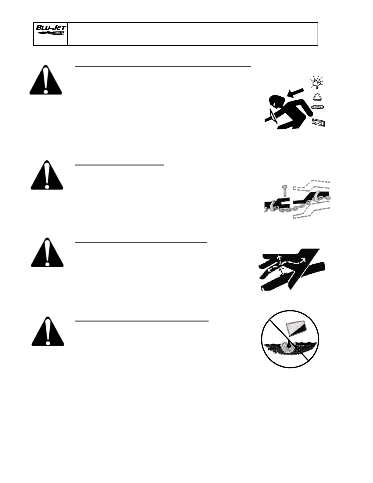
AVOID HIGH PRESSURE FLUIDS
• Escaping uid under pressure can penetrate the skin
causing serious injury.
• Avoid the hazard by relieving pressure before
disconnecting hydraulic or other lines. Tighten
all connections before applying pressure.
• Search for leaks with a piece of cardboard.
• Protect hands and body from high pressure uids.
• If an accident occurs, see a doctor immediately.
DISPOSE OF FLUIDS PROPERLY
• Improperly disposing of uids can harm the
environment and ecology. Before draining any
uids, contact your local environmental agency
for the proper waste disposal methods.
• Use proper container when draining uids. Do
not use food or beverage containers that may
mislead someone into drinking from them.
• DO NOT pour oil into the ground, down a drain, or
into a stream, pond, or lake. Observe relevant
environmental protection regulations when disposing
of oil and other harmful waste.
Safety
9
AT6020 Safety
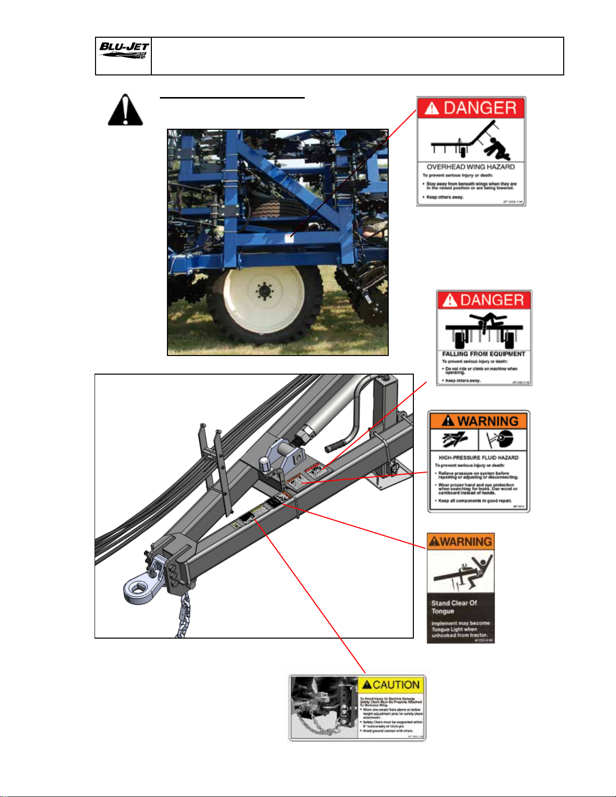
Observe Safety Signs
AP 2469-7-98
AP 2483-8-98
AP 2234-7-98
AP 222 8-90
AP 2914
10
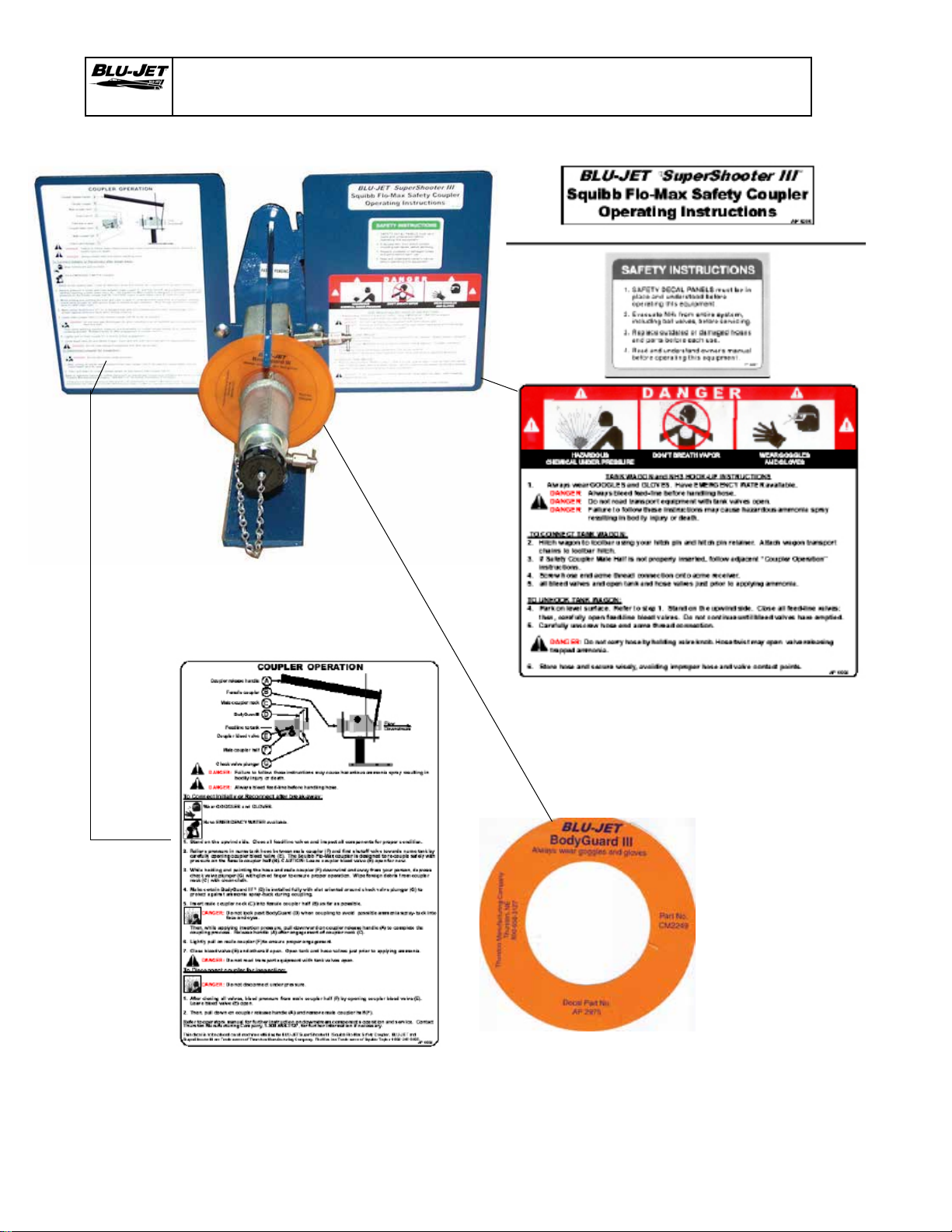
AT6020 Safety Decals
AP2973
AP2975
AP2974
AP2227
AP2972

11
AT6020 Operating Instructions
Hitch 1. The tractor must be equipped
with a drawbar and a draw-
bar safety chain clevis. For
rigid frame tractors equipped
with swinging drawbar, the
drawbar must be located in a
xed position in the center of
the tractor. Refer to your
tractor operators manual for
drawbar adjustment and
drawbar operating instructions.
NOTE:
Implement
hitch weights
are designed
to match
tractor size
ranges.
Check the
following
chart to
conrm your
particular
implement
specication.
WARNING: Tractor drawbar must be in a xed position before
transporting implement. Implement will sway or slam against
tractor resulting in equipment damage or injury to personnel.
WARNING: In case the tractor hitch pin is lost during transport-
ing. The safety chain must be attached between the implement
and tractor to prevent separated implement from running freely
and causing damage or injury.
WARNING: Do not move articulated tractor steering wheel
until everyone is clear of the equipment. Moving the steering
wheel can swing or move attached equipment which could
cause serious personal injury.
Tractor to
tool bar
connection
2. Before connecting the tool bar to the tractor drawbar, raise the
tractor three point hitch (if equipped) to prevent interference
between the implement and the tractor.
Connect the tool bar to tractor drawbar ONLY. DO NOT connect
the tool bar to any other part of the tractor. Connect the tool bar
clevis to the tractor drawbar with hitch pin. Install the safety
chain through the tractor drawbar support bracket.
3. Always use a safety hitch pin of the correct diameter. Make sure
that the hitch pin is locked in place with a safety type lock pin or
other locking device.
4. Always use a safety chain between the toolbar and the tractor.
Install the chain to the tractor drawbar support bracket. Support
the center of the chain with a clevis installed to the tractor
drawbar.
Safety
hitch pin
Safety
chain
Generic Photo
Engine
HP Range
Drawbar
Vertical Load Pounds
Category
I
II
III
IV
20
40
80
100
47
133
227
400
731
1,236
2,248
4,777
1,405
3,597
5,957
10,341
WARNING
WARNING
WARNING
12
AT6020 Operating Instructions
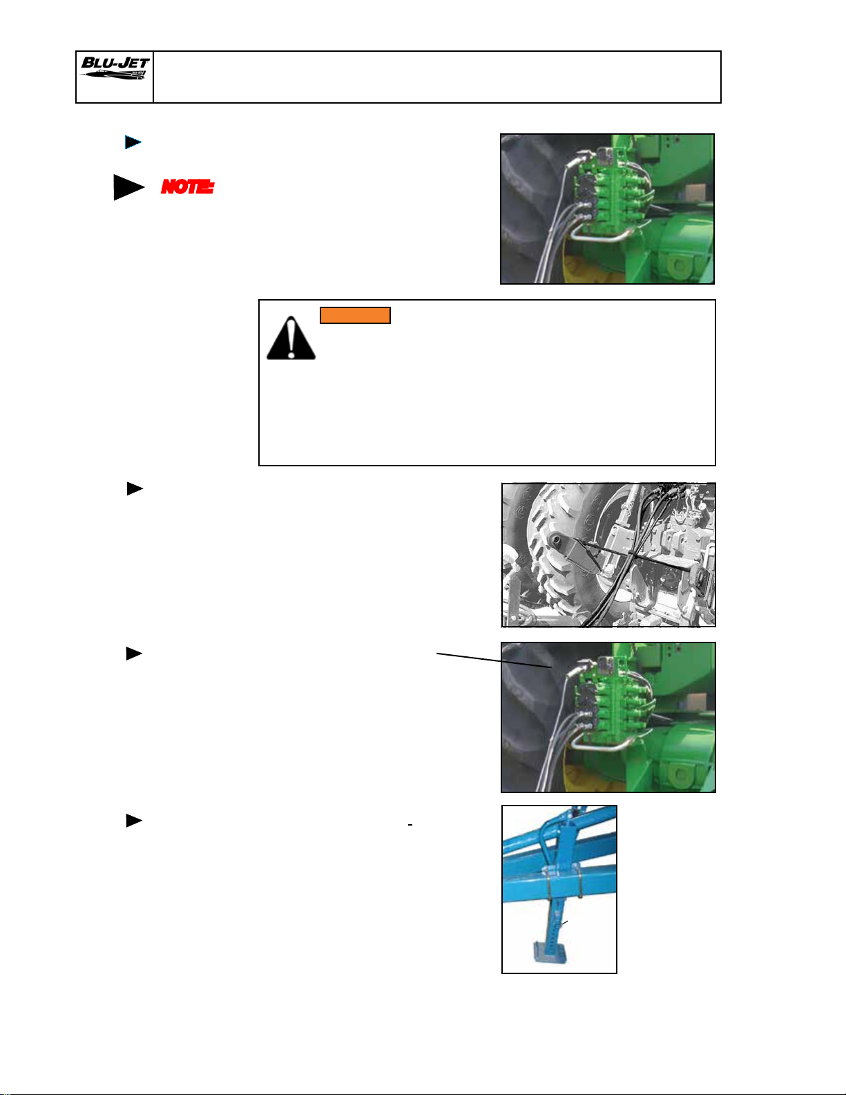
Remote
hydraulic
5. Connect the toolbar hydraulic
hoses to the tractor remote
couplers. The 1/2” hoses
supply oil to the toolbar lift
cylinders. The 3/8” hoses
supply oil to the wing fold
cylinders.
NOTE:
Always
connect the
hoses so
the toolbar
raises when
the tractor
remote con-
trol lever is
moved rear-
ward and
lowers when
the lever
is moved
forward.
6. It may be necessary to tie
the hydraulic hoses up to
keep them away from the
hitch area. A tarp strap
around the hoses and
between the two point arms
works well.
7. Attach 7 pin electrical
harness before road
transport.
8. Lower the jack and pull
ring on drop leg jack
plunger and raise the sand
pad off the ground. Secure
plunger in holes.
I
MPORTANT: Always lower the
jack stand to the ground before
disconnecting the tool bar from the
tractor.
Remote
hydraulic
Attaching
electrical
harness
Jack stand
Ring
WARNING: Hydraulic uid escaping under pressure can have
enough force to penetrate the skin. Hydraulic uid may also
infect a minor cut or opening in the skin. If injured by escaping
uid, see doctor at once. Serious infection or reaction can result
if medical treatment is not given immediately. Make sure all
connections are tight and that hoses and lines are in good
condition before applying pressure to the system. Relieve all
pressure before disconnecting the lines or performing other work
on the hydraulic systems.
WARNING

13
AT6020 Operating Instructions
9. Before leveling the machine
the tire pressure should be
checked.
Inate center section lugged
tractor tires to 56 P.S.I. Maximum
Truck tires 95 P.S.I. Maximum
Before beginning operation of
this machine the main frame
must be level.
Place tool bar on level surface.
Use the turnbuckle wrench to
loosen the lower turnbuckle
jam nut. Adjust turnbuckle with
wrench until the main frame is
level front to back. After making
the necessary adjustment,
lock turnbuckle with jam nut.
Leveling
Machine
Main Frame
10. Unlatch primary wing latch
with the cable release located
on the front of the tool bar
before unfolding tool bar.
CAUTION: To prevent serious accident or injury
do not remove wing latch cable release mecha-
nism. Wing fall may result during road transport.
NOTE: Cable must be free. Do not place
hydraulic hoses, EVA hoses or ties around
the cable.
Jam Nut
CAUTION
14
AT6020
Tighten one inch
hex nuts after
wheel adjustment.
Leveling
adjustable
gauge
wheels
One Inch hex nut
Cylinder lug adjust
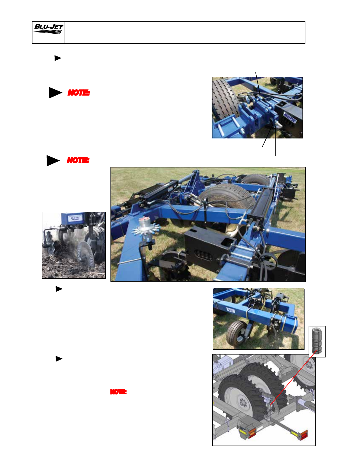
11. Check tire pressure before
adjusting.
Loosenthetwo1”x4” Hexbolts
at the top of the adjust linkage.
Loosen 1” hex nut on inside of
threaded rod. Turn 1” hex nut
on outside clockwise to lower
wingand counter clockwise to
raisewing. Secure bothnuts on
threaded rod against cylinder
lug adjust. Tighten
1” x 4” hex cap screws after
wheel adjustment.
NOTE:
Adjust until
tool bar is
level
across the
entire bar
12. Adjust pin adjust gauge wheel
to level position with the
hydraulic gauge wheel.
Operating Instructions
Pin adjust
gauge
wheel
13. Install equal lengths of cylinder
depth collars to the right and left
hand center section wheel lift
cylinders.
NOTE: Unequal depth collar installation
may result in wheel lift linkage damage.
Depth
collars
NOTE:
Coulter will
require
nal
working
depth
adjustment
in the eld.

15
AT6020
DEPTH ADJUSTMENT
1. One complete revolution equals 1/2” of
depth increase.
LOCKING DEPTH ADJUSTMENT
LINKAGE
1. Rotate depth control adjuster latch
over handle and lock in place with
(27) (BP3376) 1/4” x 2” wire retaining
pin.
LOCKED POSTION
Operating Instructions

16
AT6020
Pinch point
To prevent Injury
Keep hands clear
when extending or
retracting the swing
slide insert
WARNING
14. Nurse tank hitch can be
retracted and moved from
side to side for easy hookup.
Hitch will automatically lock
in the extended position.
NOTE:
Periodically
check Latch
mechanism to
ensure proper
latching in the
extended
position.
Nurse tank
hitch
Secondary
wing latch
Cylinder rod
maintenance
Operating Instructions
15. Mechanism must swing
freely in order to operate
properly. Installed position
must be squared with frame
to allow maximum freedom
of movement. Keep soil and
debris from area to allow
maximum movement.
NOTE: After seasonal storage,
check wing latch for freedom of
movement.
16. All exposed cylinder rods
should be greased before
seasonal storage to prevent
rusting.
Remove depth collars and
lubricate exposed cylinder
rods.
Latch in open position
before wing is folded

17
AT6020
Zerks On Wing Gauge
Wheel Pivot
(Torque 100 ft./lbs.)
Zerk
Wing Hinges
17. Lug nut Torque
1. Check every hour rst four
hours.
2. Check every four hours to
rst twenty hours.
3. Check once every fty hours
thereafter.
Lug Nut
Torque
Lubrication
Zerk
Under
Hitch
Lift Wheel Pivot Zerk
(Torque 150-180 ft. lbs.)
Operating Instructions
17. Lubrication
• Grease all zerks daily
• Grease coulters daily
Zerk
Zerks
Zerk
Wing Linkage
Zerk
Wing Linkage
18
AT6020
Zerks On Linkage
And Hinge
Operating Instructions
Lubrication
Zerks On Wing Gauge
Wheel Pivot
(Torque 100 ft./lbs.)
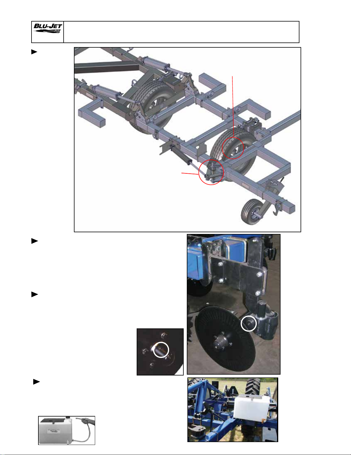
18. Grease all coulter arm pivots.
19. The plug on the coulter hub
can be removed. A zerk can
be installed. Hub and spindle
assembly should be greased
twice seasonally.
20. emergency water tank/toolbox.
Change water daily to provide
fresh clean water to ush
exposed skin or eyes.
Drain water daily in cold
temperatures to prevent
freezing and bursting tank.
Coulter
pivot shaft
lubrication
Coulter
hub
lubrication
Emergency
water tank
operation
and
maintenance
Table of contents
Other BLU-JET Farm Equipment manuals


Popular Farm Equipment manuals by other brands

Anderson
Anderson Double stretcher Operator's manual

GrainPro
GrainPro TRANSAFELINER BULK instruction manual

UNIA
UNIA MX user guide

MASSEY FERGUSON
MASSEY FERGUSON Combines MF 7340 Workshop service manual

sitrex
sitrex MX 8 Assembly, use and maintenance

Quattro
Quattro Titanium EGO400 Installation guide and user information


