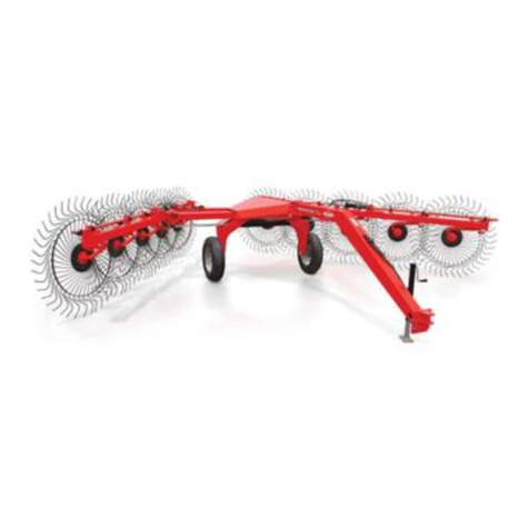
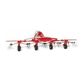
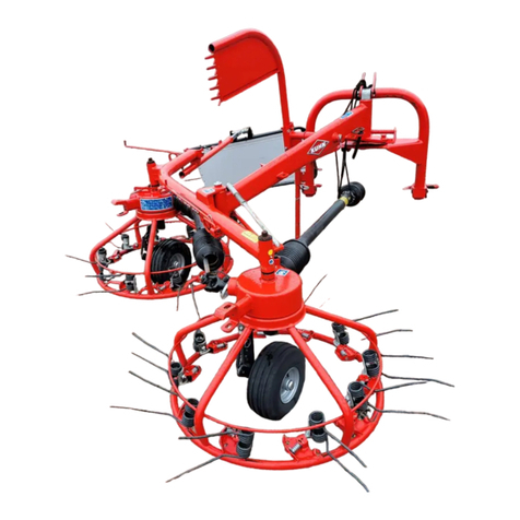
KUHN GA 6000 User manual

ASSEMBLY / OPERATOR'S MANUAL
GA 6000
GYRORAKE
N° 95313 E.GB - 10.2003

DEAR OWNER,
In buying a KUHN machine you have chosen wisely. Into it have gone years of thought,
researchandimprovements.Youwillfind,ashavethousandsofownersallovertheworld,that
you have the best that engineering skill and actual field testing can produce. You have
purchased a dependable machine, but only by proper care and operation can you expect to
receive the performance and long service built into it.
This manual contains all the necessary information for you to receive full efficiency from your
machine.Theperformanceyougetfromthismachineislargelydependantuponhowwellyou
readandunderstandthismanualandapplythisknowledge.PleaseDONOTASSUMETHAT
YOU KNOW HOW TO OPERATE AND MAINTAIN YOUR MACHINE before reading this
manual carefully. KEEP THIS MANUAL AVAILABLE FOR REFERENCE.
YourKUHN dealerwillinstruct youonthegeneral operationofyourmachine. Heisinterested
that you get the best performance possible and will be glad to answer any special questions
that may arise regarding the operation of the KUHN machine.
Your KUHN dealer can offer a complete line of genuine KUHN service parts.
These parts are manufactured and carefully inspected in the same factory that builds the
machine to assure high quality and accurate fitting of any necessary replacements.
When ordering service parts it is important that you indicate the type of machine concerned
and its serial number.
Forthisreasonpleasecompletethemodelidentificationplatediagrambelowwiththerequired
information. This will provide you with an easy reference for future service parts orders.
ABOUT IMPROVEMENTS
KUHN iscontinuallystriving to improveitsproducts and,therefore,reserves the righttomake
improvements or changes when it becomes practical to do so, without incurring any
obligations to make changes or additions to the equipment sold previously.

-1 -
CONTENTS
Page
Safety 2
Safetydecals 8
Technicalspecifications 10
Assembly instructions 10
Attachment : - Fitting to the tractor 18
-PTOshaft 18
Work position - adjustments 20
Operation 24
Forwardspeed 24
Transport 26
Parking 28
Lubrication 28
Optionalequipment 30
Electricalconnector(forNorthAmerica) 32
Conditionsoflimitedwarranty 33
Copyright2003 KUHN S.A.

-2 -
SAFETY
Theabovesymbolisusedthroughoutthismanualeverytimerecommendationsaremadeconcerningyoursafety,
the safety of others, or the good operation of the machine.
Theserecommendationsmust be madeknowntoall machine operators.
DESIGNATED USE OF THE MACHINE
TheGA6000 Gyrorake mustonlybeusedforthework for whichithasbeendesigned:raking on thegroundand
formingwindrowsofpre-mowedfodderandstraw.
Themanufacturerisnotheldliableforanydamageresultingfrommachineapplicationsotherthanthosespecified
bythemanufacturer.
Any use other than the designated operation is at the risk and responsibility of the operator.
Designated use of the machine also means :
-followingoperation,maintenanceandrepairrecommendationsgivenbythemanufacturer;
- using only genuine spare parts, equipment and accessories as designated by the manufacturer.
TheGA6000Gyrorakemustonlybeoperated,maintainedandrepairedbycompetentpersonswhoarefamiliarwith
machinespecificationsandoperationandareawareofanydangerinvolved.
Theoperator must imperatively respectcurrent legislation concerning :
-accidentprevention,
- work safety,
- public traffic circulation.
All safety advice indicated on the machine must be strictly observed.
Themanufacturerisnotheldliableforanydamageresultingfrommachinemodificationscarriedoutbytheoperator
himselforbyathirdpartywithoutpreviouswrittenagreementfromthemanufacturer.

-3 -
GENERAL SAFETY RECOMMENDATIONS
Beforeoperatingthemachine,alwaysensurethattractorandmachineareinaccordancewithworksafetyandroad
trafficregulations.
BASICPRINCIPLES
1. Inadditiontotherecommendationsgiveninthismanual,legislationonworksafetyandaccidentpreventionmust
alsobe respected.
2. Adviceis indicated onthemachine, specifying safetyrecommendationsin order topreventaccidents.
3. Beforetravellingonpublicroads,theoperatormustensurethatthemachineconformstoroadtrafficregulations.
4. Before starting work, the operator must be familiar with all machine controls, handling devices and their
functions. Once at work, it is too late to do so !
5. Useatractorequippedwithasafety cab. Keep windows and roof hatchclosed for reduced soundlevel while
operatingthePTOdriveimplement.
6. Beforestartingupthemachineandbeginningwork,checkthesurroundingarea(bewareofchildren!).Make
sure there is sufficient visibility.
Keepall people andanimals away fromthedanger zone ofthe machine (riskof projection !)
7. Carryingpeople or animalson the machinewhen working orintransport is strictlyforbidden.
8. Machine must only be attached to tractor using means provided and in accordance with current safety
standards.
9. Whenattachingorremoving the machine, place theparking standinto thecorresponding position.
10. Special care shouldbetakenwhen attaching or removingthemachine from the tractor.
11. Before attaching the machine, ensure that the front tractor axle is sufficiently ballasted.
Ballast is to be placed on the supports provided in accordance with instructions of the tractor manufacturer.
12. Donotsurpassthemaximumaxleloadortheoveralltransportweightasprescribedbythetractormanufacturer.
13. Do not exceedthemaximumtransport width authorizedby roadtrafficregulations.
14. Beforetransportingthemachineonpublicroads,ensurethatalllegallyrequiredguardsandindicators(lights,
reflectors...) arein place andin good operation.
15. Alloperatingcontrols(cords,cables,rods...)mustbepositionedsothattheycannotbesetoffaccidently,risking
accidentordamage.
16. Before traveling on public roads, put the machine into its transport position as instructed in this operator’s
manual.

-4 -
17. Neverleavethetractorseatwhilethe machineisoperating.
18. Drive speed must be adapted to ground conditions as well as to roads and paths.
Alwaysavoidabruptchangesofdirection.
19. Precisionsteering,tractoradherence,roadholdingandefficientbrakingareinfluencedbythetypeofimplement,
weight,ballastoffrontaxle,groundorroadconditions.Itisthereforeofutmostimportancetobecautiousinevery
givensituation.
20. Beparticularlycautiouswhenturningcorners,payingattentiontomachineoverhang,length,heightandweight.
21. Keepclearofthemachineoperatingarea.
22. WARNING ! Danger of crushing and shearing can exist when components are operated by hydraulic or
pneumaticcontrols.
23. Beforeleavingthetractororbeforeadjusting,maintainingorrepairingthemachine,turnofftheengine,remove
the ignition key and wait until all moving parts have come to a complete stop.
24. Donotstandbetweenthetractorandthemachineunlessthehandbrakeistightand/orstopshavebeenplaced
underthewheels.
25. Beforeanyadjustments,maintenanceorrepairsarecarriedout,ensurethatthemachinecannotbestartedup
accidentally.
PRECAUTIONS TO BE TAKEN BEFORE OPERATING THE MACHINE
1. Do not wear loose clothing which could be caught up in moving parts.
2. Wear the individual protection equipment corresponding to the work which is planned (gloves, shoes, eye
protection, helmet, ear protectors...).
3. All operating controls (cords, cables, rods ...) must be positioned so that they cannot be set off accidentally,
causing accident or damage.
4. Beforeoperatingthe machine,checkthetightnessof allnutsandbolts, particularlyonrotatingparts(blades,
tines, knives, spades ...)
5. Beforeoperatingthemachine, ensurethatall safety guards are firmly inplace and ingood condition. If worn
ordamaged,replaceimmediately.
ATTACHMENT
1. Whenattachingorremovingthemachinefromthetractor,ensurethatthemachinecannotmoveunexpectedly
(secure with wedges if necessary).
2. Donotexceedthemaximumallowabledownpressureappliedbythemachinedrawbaronthetractorhitchpoint.
3. Ensurethatverticaland horizontal pivot angles betweenmachinetongueandtractorhitchpointare sufficient
toallowsafeoperation.
-5 -
POWERTAKE-OFF
1. Useonly the PTOshaftsupplied with themachineor recommended bythemanufacturer.
2. PTO guards must always be in place and in good condition.
3. CheckforcorrectPTOoverlapwhen atworkandintransport.
4. BeforeattachingorremovingthePTOshaft,disengagePTOshaft,turnoffengineandremoveignitionkey.
5. IfaprimaryPTOshaftisequippedwithaslipclutchorafreewheel,thesemustbefittedonthemachinePTO.
6. Ensure that PTO shaft is always correctly fitted and locked into place.
7. Make sure guards are correctly in place and secured with the safety chains provided.
8. BeforeengagingPTO,ensurethatPTOspeed(rotationalfrequency)anddirectionofrotationareinaccordance
withmanufacturer'srecommendations.
9. Beforeengaging PTO,keepallpeopleand animalsclearfromthemachine.
10. NeverengagePTOshaftwhentractorengineisturnedoff.
11. NeversurpassthePTOanglerecommendedbythemanufacturer.
12. WARNING!RotatingelementscancontinueturningmomentarilyafterPTOisdisengaged.Keepclearuntilall
rotating elements are at a standstill.
13. Whenremovingthemachine,placePTOshaftonthesupportsprovided.
14. Fit the safety cap on tractor PTO.
15. ReplaceanywornordamagedPTOguardsimmediately.
Rotationspeed ...rpm (American Measure)is alsoexpressed in metric measure :Rotational frequency ...min-1.
Both unitsare equivalent,for example: Rotationspeed 540rpm equals Rotationalfrequency 540 min-1.

-6 -
HYDRAULICSYSTEM
1. Beware! The hydraulic circuitisunderpressure (maximum working pressure:200bars/2900 psi).
2. When fitting hydraulic motors or cylinders, ensure that connections have been made correctly, as per
manufacturer’sinstructions.
3. Before connecting hoses to the tractor hydraulics, ensure that tractor and machine circuits are not under
pressure.
4. Itisstronglyrecommendedthattheoperatormarksthehydraulicconnectionsbetweentractorandmachineto
avoidmakingawrongconnection.WARNING!Functionscouldbereversed(forexample:lift/lower).
5. Regularlycheckthehydraulichoses!Incaseofnormalwear,replacethehydraulichosesevery5years.Damaged
or worn hoses must immediately be replaced .
Whenreplacingthehydraulichoses,makesuretousehoseswiththespecificationsandqualityrecommended
bythe manufacturer ofthemachine.
6. Should a leak be found, take all necessary precautions to avoid accidents.
7. Any liquid under pressure (particularly oil from hydraulics) can penetrate the skin and cause severe injury. If
injured,see a doctor immediately,therecould be dangerofinfection.
8. Beforeanyadjustments,maintenanceorrepairsarecarriedout,lowerthemachine,depressurizethecircuit,turn
offtheengineandremoveignitionkey.
TIRES
1. Beforeanyworkisperformedonthewheels,ensurethatthemachinerestsonthegroundandisperfectlystable
so that it cannot move accidentally (put wedges in place).
2. Assembly,disassemblyandrepairofwheelsandtiresmustonlybecarriedoutbycompetentpersonswhoare
equippedwithstandardizedtools.
3. Checktirepressureregularly!
Respectmanufacturer’srecommendationsontirepressure.

-7 -
MAINTENANCE
1. Before checking for any machine malfunction and before adjusting, maintaining or repairing the machine,
disengage PTO, turn off engine and remove ignition key.
2. Check tightness of nuts and bolts regularly. Retighten if necessary.
3. If the machine is raised, prop it up in a stable position before carrying out any maintenance work.
4. Whenreplacing a working part,wearprotection gloves andonlyuse standardized tools.
5. It is forbidden to discard any oil, grease or filters. These must be given to waste disposal organisations to
protecttheenvironment.
6. Disconnect power source before any work is done to the electric system.
7. Check safety guards regularly, particularly those that are subject to wear. Replace immediately if damaged.
8. Spare parts used must be in accordance with specifications and standards as defined by the manufacturer.
Use only genuine KUHN parts !
9. Before any electric welding is carried out on tractor or attached machine, disconnect generator and battery
terminals.
10. Repairs on elements under pressure or tension (springs, accumulators etc...) must only be carried out by
competentpersonswithstandardizedequipment.
SPECIAL SAFETY RECOMMENDATIONS
1. When changing the machine over from the work to the transport position or vice versa, danger of crushing
and shearing can exist.
Be especially careful and keep all persons away from vicinity of the machine when maneuvering.
2. Donottowthemachineataspeedexceedingthelimitsinforceinthecountryinwhichthemachineistransported.

-8 -
SAFETY DECALS
The following safety pictorials have been placed on your machine in the areas indicated.
They are intented for your personal safety and for the safety of the people working with you.
The text shown on them gives their precise meaning. Keep the pictorials clean. Replace
them when they are faded.
2
1

-9 -
3
4
5
6
7
8

-10 -
TECHNICAL SPECIFICATIONS
Tractorattachment Drawbar
Working width (with single swath) adjustable from 3.50 m (11' 6") to 5.8 m (19')
Totaltransportwidth 2.95 m (9' 8")
Overalllength 7.3m(24')
Totalweight 1100 kg(2420lbs)
Numberoftinearms 20
Numberoftines 60
Tinearms/Guards fixed
Shiftinginto transport /working position by hydrauliccontrol
Hydraulicoutletsrequired 1 x double acting outlet and
1 x single acting outlet
Electricconnectionrequired 1 x 7 pin plug
PTOshaft Wideangle with torquelimiter
PTO speed (rotational frequency) 540 rpm (min-1)
Tyres / Tyre pressure Hyperballon (18 x 8.50 - 8) / 2 bars (29 psi)
Powerrequirement 30 kW (40 hp)

-11 -
ASSEMBLY
1. MOUNTING THE WHEELS AND THE WHEEL AXLES (figure A and photo B)
Slidethecylindricalhubprotectors(01)ontoaxles(N)untiltheyseatontheaxles'shoulders.Thenslidetheconical
greyprotectors(02)ontotheaxleswiththeconicalsidefacingthewheelbearinglocations.Thegreyprotectingplugs
areseatedtightlyonthe spindle’s shoulders. Drive themin placeusing a driverand applya blow witha hammer.
Fill wheel caps (Q) with grease.Also grease the space between both bearingslocatedinsidetherims. Install
the 2 wheels (L) on axles (N). Insert conical spring washer (O) and fit low self locking nut (P) (M 16). Tighten to
12 daNm / 89 ft.lbs. Fit wheel caps (Q) in place (figure A).
Make sure to install the conical washers (O) with the convex side against the nut (P).
Positiontheundercarriagesothattheheightadjustmentcrankhandles(R)aredirectedtowardstherear,remove
theprotectivescrewplugs,insertundercarriageboltsintotherotoraxlesflanges(S)andsecureinplaceusingself
locking nuts (U) (tighten to 28 daNm - 207 ft.lbs) (photo B).
Note: Toensureaccuraterotorlevelling,shims(V)mayhavebeenwiredtotheundercarriagemountingplatesat
the factory. It is important that these shims (V) are kept in their original location when assembling the
undercarriages (T) to the rotor axles (S) (photo B).
AB

-12 -
2. ASSEMBLING THE TWO MACHINE HALVES (photos 1 and 2)
- Assemble the 2 front (1) and rear (2) parts using 2 pins (A), 2 roll pins (G) (diameter 8 x 65) and 2 roll pins (H)
(diameter5 x 55)(photo 1).
- Position rear lights wiring harness and the hydraulic hoses (R) on top of rear beam (T) and mount hose
cover (C) (photos 1 and 2).
- Mountdoubleactingcylinder(V)usingaxle(O)and2rollpins(P)(diameter8x30)oncylinderbarrelside (photo
1A) and using axle (Q) and 2 roll pins (D) (diameter 4x30) on cylinder rod side (photo 2).
- Connect hydraulic hose (L) to rear rotor lock (H) (photo 2).
- Pass hydraulic hose (B) through the rear rotor axle (photo 2) and connect it to rear undercarriage cylinder (D)
(see photo B, page 11).
3. FITTING THE FRONT SAFETY GUARDS (photos 3 and 4)
- Fit the front guards (E), with their curved ends facing downwards, on each side of the front frame (I) with 4
hexagonalscrews(J) (M 12 x35),4lock washers (M 12),4hexagonalnuts (M 12), 4hexagonalscrews(K) (M
8 x 40), 4 plain washers (diameter 9 x18 x 1.5) and 4 self locking nuts (M 8) (photo 3).
- Fit the hose support (S) to the front right guard using a U-bolt (M) and 2 self locking nuts (N) (M 8) (photo 4).
- Connectthe hydraulic hosesandthewiringharnesscable to thesupport(S)usingtheplasticclamp collars (D)
(length176mm)(photo4).
4. MOUNTING OF THE REAR CONSOLE (photo 5)
Mounttherearconsole(W)onthecasting(X)bymeansof4self-lockingscrews(Y)(M16x25)(torque21daNm/
155ft.lbs)aftercheckingthat the electric cables (Z)for the rearsignalling havebeen pulled through.

-13 -
5
3
4
1 2

-14 -
5. FITTING THE REAR SAFETY GUARDS AND CRANK HANDLE (photos 6, 6 A and 7)
- Fit the 2 rear guards (J) on the console (K) using 6 screws (W) (M 8 x 85), 12 plain washers (diameter 8 x 18
x 1.5) and 6 self locking nuts (M 8) (photo 6).
- Fix the stiffening rod (L) on the left rear guard using 2 self-locking screws (X) (M 16 x 25), 2 hexagon screws
(Y) (M 12 x 35) and 2 plain washers (diameter 12.5 x 25 x 1.5) (photo 6).
- Fixthelinkrod(I)using2hexagonscrews(Y)(M12x35),2selflockingnuts(M12)and4plainwashers(diameter
12.5 x 25 x 1.5) (photo 6).
- Fit the handle support (B) by means of 2 hexagonal screws (H) (M 8 x 25) and 2 self-locking nuts (M8) (photo
6).
- Connectthe 2 rearprotectors (J) togetherusing 2 bars(M), 2 hexagonscrews (Z) (M8 x 55)and2 self locking
nuts (M 8) (photo 6 A).
- Mount the flexible joint (Q) on the crank handle(R) with a bush (U) and a roll pin (G) (diameter 6x30), slide the
crank(R)throughtheholeinthehandlesupport(B),thenconnecttheflexiblejoint(Q)totheadjustingscrew(O)
with a bush (U) and a roll pin (G) (diameter 6x 30) (photos 6 and 7).
6. FITTING THE LIGHTING AND SIGNALLING ELEMENTS (photos 8, 9, 10 and 11)
- Simultaneouslyfixthefrontsignallingpanels(P)andtheirsupports(S)onthefrontguards(E)using8hexagon
screws (V) (M 10 x 25), 8 self locking nuts (M 10) and 8 plain washers (diameter 11 x 24 x 2) (photo 8).
The red corners on the front panels must be pointing upwards and outwards (photo 9).
- Fixthewhitelights(F)(notchpointingdownwards)aswellasthewhitereflectors(C)onthefrontsignallingpanels
(P) (photo 9).
- Connectupthefrontconnectingplugstotheconnectingplugsontheelectriccablesmakingsurethatthelocking
tab(1) of thefemale connector (2) is fullyengaged over the peg(3) of the maleconnector (4) (fig.A)and
attach the cables to the guards (E) using the plastic clamp collars (D) (length 176 mm) (photo 8).
- Simultaneouslyfittherearsignallingpanels(P)thepanelsupports(F)andthewheelwedgesupports(G)onthe
rearguards(J)using18 hexagonscrews(V)(M10x25),18selflockingnuts(M10)and18plainwashers(diameter
11 x 22 x 2) (photo 10).
- Bolt wheel wedge assemblies (X) on supports (G) with 8 hexagonal bolts(Y)(M8x12),8self-lockingnuts
(M 8) and 8 plain washers (dia. 9 x 18 x 1.5).
The red corners on the rear panels must be pointing upwards and outwards (photo 11).
- Fittherear leftlight (N)whoseplugisidentified by a white cablesheath(highlightedingreyonfigureA)and
marked «L» on the rear left panel (photo 11).
Fit the rear right light (O) whose plug is black and marked «R» on the rear right panel (photo 11).
- Fixtheelectriccablesontherearguardsusingclampcollarsandselfstickingbases(A)andconnectplugs (photo
10) making sure that the locking tab (1) of the female connector (2) is fully engaged over the peg (3) of
the male connector (4) (fig. A).
- Fixthe triangularreflectors (T) onthe rearpanels (P) using4 countersunkscrews (M 5x 25)and 4 selflocking
nuts (M 5) (photo 11).

-15 -
10
7
11
A
6

-16 -
7. FITTING SWATH SCREEN
- Install the 4 plastic bushes (M) in both arm ends of the swath screen adjustment parallelogram (U) (photo 12).
- Fit the swath screen’s parallelogram adjustment (U) on the 2 pivot pins (V) using 2 roll pins (W) (diameter 6
x 40) and 2 flat washers (N) (diameter 30 x 40 x 1.5), inserting washers between the roll pins (W) and the
parallelogramarm(U)(photo12).
- Installthecounter nut (I) andtheintermediary long connecting rod(J)onto the threaded rod(O),then slide the
shortrod(L)intothelongconnectingrod(J)(photo12A)andmounttheshortconnectingrodyoke(L)ontherear
armof the adjustmentparallelogram (U) bymeans of apin (H) and2 roll pins(K) (diameter 5x20)(photo 12).
- Fit the swath screen (X) on the support (Y) in one of the vertical positions with 2 hexagonal screws (Z) (M 10 x
30), 2 self locking nuts (M 10) and 2 plain washers (diameter 10.4 x 24 x 4) (photo 13), the latter must be fitted
onthe screws(Z) in orderto be placedbetween thescreen (X) andthe support (Y).
- Now adjust the length of the connecting rod by proceeding as follows :
. make sure the machine is in transport position and the threaded insert (P) is located approx. in the middle
ofthe adjusting rangeof screw (Q) (photo12 A),
. foldthe swath screen (X) inwards(see arrow) untilin contact withguard stop(R) (photo 13A),
. rotate the intermediary long connecting rod (J) on the threaded rod (O) until mounting holes for lock pin (S)
line up. Install lock pin (S) and secure with R-clip (T) (photo 12 A),
. tighten the counter nut (I) (photo 12 A).
8. FITTING TINE ARMS AND TINES
- Fittinearms(E) onto the oscillating shaftsand attachusing rollpins (F)(diameter 12x 55 anddiameter 7x 55)
(photo14).Fitthetinearms(E)ontotheoscillatingshaftsmakingsurethatthebentformofthearmsfaces
always forwards when looking in the direction of rotor rotation (see arrow on photo 14).
ATTENTION: Makesurethattheroll pins are fitted 180° to each otherandthattheslotsarefacingthedirection
ofrotation(seedrawingonphoto14).
Besurethatthe matingsurfacesof tinearms(E)and theirshaftsare cleanandlightly coated
with a never seize compound.
- Fit tines (A) perpendicularlyunder tine arms(E)sothattinesareslantingawayfromthedirectionofrotation
(seearrowon photo 14A).
- The following items are needed to fit a tine :1 screw (B) (M 12 x 80), 1 self-locking nut (G) (M 12) (torque
8.5 daNm / 6 ft.lbs), 1 flat washer (C) (diameter 13 x 35 x 7), 1 spring washer (F), 1 wedge (D).
Make sure all items are positioned correctly, as shown on photo 14 A.
Incorrect fitting of the tine arms and the tines can cause serious damage to the machine.

-17 -
14 14A
13A
R
X
12A

-18 -
ATTACHMENT
1. FITTING TO THE TRACTOR
TheGA 6000 canbefittedtoalltypesoftractors,preferablythosewithapullbar.Adjusttheheightofthedrawbar
using crank handle (M) of stand (D) (photo 15).
Connectupthehoses(F)attachedtothecylinderwhichplacesthemachineintheworkpositiontoadoubleacting
hydraulicoutletandhose(F’)whichsuppliestheliftcylinderstoasingleactinghydraulicoutlet.Hoses(F)aremarked
withacolouredring(photo16).Openthelockvalvelocatedonthehydraulichoseend(F').Connectelectricplug
(H) to a 7 pin electric socket at the rear of the tractor (see photo 16).
With the machine attached to the tractor, turn handle (M) to lift the parking stand (D) from the ground.
Pullparking stand (D) outwards,folditupwardsandlockitin its position withtheRclip(P)afterplacingthe crank
(M) in the hook (C) (photo 15).
Note: The GA 6000 for North America are supplied as standard equipment with a coupling clevis kit and
a ANSI / ASAE 338.4 safety chain (see page 30).
2. P.T.O. SHAFT
Connect the PTO shaft to the 540 rpm (min-1)tractor drive (with the safety clutch fitted on the machine side).
Make sure PTO length is correct :
1° When the PTO is in its maximum extended position, a minimum tube overlap of 300 mm (12") must be
maintained.
2° When the PTO is in its maximum overlap position (retracted), tubes should not butt against the yokes.
Asa safety measurea clearance ofat least2 cm (0.8")must be maintained.If this isnot the case,shorten the
two transmission tubes and the two guard tubes by the same length(fig.A&B).Bevelandcleanthetubes
(fig. C) and grease the inside of the outer tube (fig. D).
3° NeveroperatethePTOattoogreatanangle(30°maximum).
Theserecommendationsandadjustmentsmustberespectedtoavoiddamageorpremature
wear of the PTO.
Never connect the PTO to the 750 or 1000 rpm (min-1)tractor drive.
To avoid accidents which could be serious, make sure that the guards are always correctly
in place and secured with the safety chains provided. On the machine side the safety chain
mustbeattachedaroundoneofthedrawbararms(photo15).Wornordamagedguardsmust
bereplacedimmediately.
Table of contents
Other KUHN Farm Equipment manuals
Popular Farm Equipment manuals by other brands

Jacobsen
Jacobsen HR6010 ROPS Cab Operator's manual

DuraTech Industries
DuraTech Industries HAYBUSTER CMF-1150 Operating Instructions and Parts Reference

Bison
Bison SVH-1 Operator's manual

Arrowquip
Arrowquip THE MAJOR product manual

TKS
TKS K2 CombiCutter Operator's manual

MANN LAKE
MANN LAKE HH-190 quick guide