manuals.online logo
Brands
  1. Home
  2. •
  3. Brands
  4. •
  5. FPM Agromehanika
  6. •
  7. Farm Equipment
  8. •
  9. FPM Agromehanika 627 712 Guide

FPM Agromehanika 627 712 Guide

ASSEMBLY / OPERATION / MAINTENANCE
SPARE PARTS LIST
03.2017
________________________________________________________________________________
ROTARY
MULTI-DISC
MOWERS
Email: razvoj @ fpm-agromehanika rs
info @ fpm-agromehanika rs
prodaja@ fpm-agromehanika.rs
Web: www.fpm-agromehanika.rs
SERBI
FPM 627 712
FPM 627 713
FPM 627 726
FPM 627 678
USER WARNING
By buying this machine, you have made a wise choice. Many years of thought, research, and
perfectionism have been invested in it. Like thousands of other users, you will also realise that you
currently own a machine created by state-of-the-art engineering, know-how and field testing. You
have purchased a reliable machine, however good performance and long service life may be
expected only if you use it properly.
This user manual contains all of the necessary information for achieving optimal performance with
your machine. However, this performance depends on how thoroughly you have read this manual
and applied the knowledge. This is a simple machine; however, many obvious defects resulting
from poor performance may be overlooked due to neglecting natural wear and tear of wearing
parts, or operating a poorly adjusted machine. Do not think you know how to operate and maintain
the machine before reading this manual you should always have at hand.
Our service representatives and sales and service centres with trained personnel offer you original
parts for your rotary mower. These parts are manufactured and carefully inspected at the same
facility where mowers are produced, in order to ensure high quality and precision assembly upon
replacement.
ROTARY MULTI-DISC MOWERS MANUFACTURED BY:
FPM AGROMEHANIKA D00 BOLJEVAC.
Rotary multi-disc mowers meet the requirements of the Machine Safety Regulation (Official
Gazette of the Republic of Serbia No. 13/2010) with regard to stability and protection of parts or
assemblies that may put the operator at risk with its function or form.
IMPROVEMENT: FPM Agromehanika d.o.o. strives to continuously improve its products
and therefore reserves the right of modification or improvement,
without having to modify or improve previously manufactured or sold
equipment.
The specifications given in this manual are correct as of date of issue.
All print and image rights are reserved by:
FPM AGROMEHANIKA DOO BOLJEVAC
DECLARATION OF CONFORMITY WITH THE SAFETY REGULATIONS SET OUT IN THE
DIRECTIVE 2006/42/EC IS AN INTEGRAL PART OF THIS OPERATION AND MAINTENANCE
MANUAL.
Issued by: FPM AGROMEHANIKA Boljevac
Printed:
Year: 03.2017.
PAGE TABLE OVERVIEW
PARTS GROUP
5 Limited warranty
6 - 9 Safety
10
-
12
Warning labels
13 Technical specifications
13 General information
15 - 18 Assembly instruction
19 Hydraulic installation
20 Joint coupling — PTO shaft
21 Attaching the mower to the tractor
22
Transporting the mower
23 Adjusting the cutting unit for operation
24 Adjusting the cutting height
25 Operating the mower
26 - 27 Lubrication
28
-
29
Adjustments and maintenance
30 Parking the mower
31 Maintenance table
32 - 33 Checking the cutters and cutting discs
34 Storing the mower
35 Declaration of Conformity 2006/42/CE
36 - 60 Spare parts list
Page 3
C O N T E N T S
N
o
065053
PLEASE READ CAREFULLY!
You will find warning labels “ATTENTION;” “CAUTION;” and “DANGER” in this manual and on the
machine. The warnings bring your attention to personal safety and safety of others who work with
you, since they need to read the warnings, too.
PERSONAL SAFETY
ATTENTION: The word “ATTENTION” is used where the operator’s and other individuals’ safety
from accidents is required.
CAUTION: The word “CAUTION” is used to indicate a potential risk for the operator and other
personnel of serious injury that may occur suddenly. This word is used frequently
as a warning for the operator and other individuals for the purpose of preventing a
surprise when using the mower.
DANGER:
The word “DANGER” is used to indicate forbidden action that may involve risk.
ALL ADDITIONAL WARNINGS SUCH AS “NOTICE” AND “IMPORTANT” INDICATE SPECIAL
SAFETY-RELATED INSTRUCTIONS REGARDING THE MOWER.
MOWER SAFETY
NOTICE: THIS SINGLE WORD WARNS THE OPERATOR ABOUT POTENTIAL RISK OF
MOWER DAMAGE IN CASE OF FAILURE TO OBSERVE PARTICULAR
INSTRUCTIONS.
IMPORTANT:
THE READER IS INFORMED ABOUT THINGS TO KNOW FOR THE PURPOSE
OF PREVENTING MINOR DEFECTS IN CASE HE/SHE MISSED THEM.
WARNING!
IN CASE OF FAILURE TO OBSERVE ANY OF THE ABOVE WARNING
LABELS, “CAUTION,” “ATTENTION,” AND “DANGER”, SERIOUS
PHYSICAL INJURY MAY OCCUR.
Page 4
LIMITED WARRANTY
For each original unit delivered to the user by the FPM Agromehanika AD Boljevac distribution
network, the manufacturer issues a warranty in accordance with the Standardization Act and
Machinery Safety Regulation (Official Gazette of the Republic of Serbia No. 13/2010) guaranteeing
that each mower part is new, free from defects in materials and workmanship, for the period of one
year from the date of delivery of the machinery to the end user, subject to condition that the
machinery is used and maintained in accordance with the instructions given in this operation and
maintenance MANUAL.
EXCEPTIONS:
1.-
Wooden parts are not covered by the warranty.
2.-
Parts not manufactured by FPM Agromehanika AD Boljevac (rubber and plastic
components, belts connecting PTO shaft, PTO shaft guard, hydraulic cylinder with
connection tubes etc.) are not covered by this warranty, but by the respective
manufacturer’s warranty.
3.-
Parts subject to normal wear and tear during use, such as: V-belts, cutters, tires, swath
boards, cutter brackets, sliders under the cutting unit, canvas cover.
4.-
The warranty lapses in case of misuse or abuse, improper or negligent use, or accident
damages. The warranty also expires in case of using non-original parts, and the
manufacturer may not be held liable for any transport damages.
THE MANUFACTURER MAY NOT BE HELD LIABLE FOR ANY LOST PROFITS AS A RESULT
OF MOWER DEFECT OR INJURIES TO THIRD PARTIES, NEITHER FOR ADDITIONAL COSTS
INCURRED FOR REMOVING AND REPLACING PARTS.
The buyer shall be liable and bear the costs for:
1.-
Regular maintenance, such as lubrication, refilling oil, small adjustments, etc.
2.-
Transport of the machinery to the service location and back within the warranty period.
3.-
Travel time of the authorized service representative to the mower owner and back, or
delivery of the mower to and from the workshop after the repair.
This warranty does not apply to a mower that has been altered or modified without our express
permission, or repaired by another person outside the authorized service.
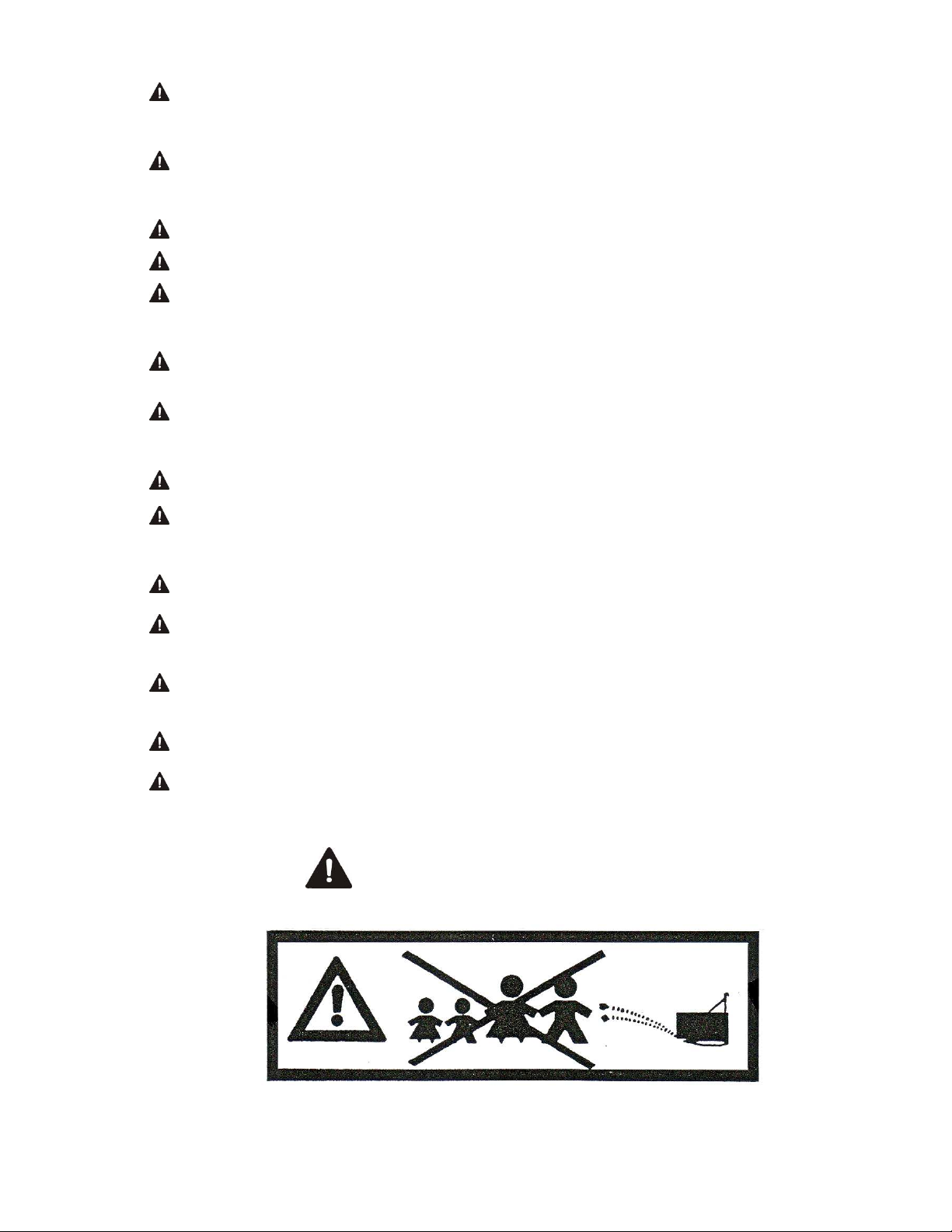
The warranty is subject to strict observance of the warnings:
- any warnings given in this manual must be observed, and all protective covers regularly
inspected and replaced, as required.
A warranty for parts that are not new is excluded.
Individuals working in our production plant are not its official representatives and are therefore not
authorized to assume any obligations in its name or on its behalf.
No warranty shall cover product equipment in excess of that specified, and the manufacturer may
not be held liable for injuries resulting from such use.
Page 5
S A F E T Y
Most accidents occur during work, maintenance, or transport due to non-observance of the
fundamental safety requirements. This is why you are the most important person for operating and
maintaining your mower. Regardless of whether you are working alone, with your family members,
or with other persons, always read and observe the basic method of operation. Additionally,
warning labels are affixed to the mower that serves as a reminder to always observe safety
practices.
- The indicated operation, maintenance and safety instructions must be strictly observed
at all times in order to ensure safe and secure mower operation.
- Before beginning work, the operator must be aware of the functioning principle of all of the
mower components. It may be too late for that during work. First and foremost, learn how
to disconnect the mower quickly and safely in case of emergency.
- The operation and maintenance manual must be kept for the entire service life of the
machine.
- Metal nameplate must always be legible, visible and clean.
- When attaching or detaching the mower to or from the tractor, always put the support foot
in the appropriate position (safety).
- Be especially careful when attaching or detaching the mower to or from the tractor; the
area around the lifting device is dangerous.
- Check the tractor front wheels for damages prior to operation. Attach weights to the
provided place.
- Observe the maximum permissible axle load and total weight. Due to the added weight,
the load is redistributed on the wheel axles.
- Use a cab tractor for road safety requirements. Keep all windows closed during operation.
- Prior to starting the mower, even for a very short distance, always bring it in its transport
position. Observe the permissible overall dimensions for transport.
- Prior to driving on public roads, secure the mower for safe transport
and observe the road traffic regulations.
In special circumstances, use lights to signal danger, if not contrary to traffic regulations.
- Never transport others on the mower or the tractor during work or transport.
- Never transport an unsecured mower.
- Never transport an operating mower.
- Never turn on the connection shaft when the mower is in the transport position.
- Never leave the driver’s seat when the tractor operates.
- Every time before using the mower check whether all parts (nuts, screws, etc.) are
sufficiently tightened, and secure the discs and cutters.
- If worn out or damaged, cutters, discs and their fasteners (nuts, screws, etc.) must be
replaced with FPM AGROMEHANIKA d.o.o BOLJEVAC original parts.
Page 6
- For safety reasons, check whether the canvas cover is properly secured and attached to
the frame. If damaged or worn out, replace it immediately with original cover by FPM
AGROMEHANIKA DOO BOLJEVAC.
- Before adjusting, lubricating, or cleaning the mower, lower it to the ground, turn off the
tractor engine, remove the ignition key, turn off the PTO shaft, and apply the tractor
parking brake.
- Wait until all moving parts have come to a stop before approaching the mower.
- Keep away from all mower parts while working.
- Never wear baggy clothes that may be caught into the rotating mower components.
Always wear tight-fitting clothes. Always wear personal protective equipment, safety
goggles, protective gloves and footwear, especially when working on rocky soil.
- Fasten the PTO shaft guard with the provided chains. (PTO shaft guard may not turn). If
the guard is damaged, replace it immediately.
- The operator must ensure that no individuals or animals are in the work area of the
mower, prior to switching the mower on and beginning work. Always keep the consequences of
irresponsible and unsafe work in mind, since this may cause grave harm.
- Remove all foreign objects from the field prior to beginning work.
-
IMPORTANT:
Never work near the roads, pedestrian areas, public spaces (parks, schools,
etc.), and or rocky soil, in order to avoid risk of accidents resulting from
ejected objects.
- Never work when driving in reverse.
- Unauthorised persons, persons without a driving licence, or persons without appropriate
mental and physical abilities are strictly forbidden to operate the mower.
- Only reliable individuals are permitted to operate the mower. Children under 16 are
strictly forbidden to operate the mower.
- Only work under optimal light and visibility conditions.
- After the end of the season, authorized service technician should inspect your mower,
bring it to operable condition, especially regarding the rotor cutters, and tighten all
parts (nuts, screws, etc.) with a required tightening torque.
NEVER IGNORE THESE WARNINGS.
Page 7
Page 7
S A F E T Y
ATTACHING THE MOWER TO THE TRACTOR
- Before coupling and decoupling the mower to or from the tractor, lock the hydraulic
controls in order to prevent unintended raising or lowering.
- When coupling your tedder, observe the category of the tractor and tedder linkages; they
have to match.
- The area around the attachment points is especially hazardous. There is a risk of injury
when coupling linkages.
- Never stand between the tractor and the mower when using external hydraulic controls.
- Watch out for and prevent any lateral movement of the linkages when the mower is in the
transport position.
- When driving on public roads with the mower in the transport position, tractor hydraulic
controls must be locked in order to prevent unintentional lowering.
Never use the mower on sloped terrain, or transport the mower by using a tractor with a
narrow wheel track.
NEVER IGNORE THESE WARNINGS.
S A F E T Y
USING THE PTO SHAFT
- Only PTO shafts supplied with the tedder and approved by the manufacturer may be used.
- All PTO shaft guards must be attached and in orderly condition.
- Ensure proper pipe overlap in the transport and operating position.
- Attaching and removing the PTO shaft may be performed only when the tractor output
shaft and the engine are turned off, and the ignition keys are removed.
- Place the star ratchet clutch towards the tedder when attaching the PTO shaft.
- Always make sure to properly attach the PTO shaft.
- Secure the PTO shaft guards with the chains from rotating; always observe the
instructions for the PTO shaft.
- When the mower is not in operation, always secure the PTO shaft with a chain as shown
in Figure 54 (page 34).
Page 8
- If you have doubts about the PTO shaft operation, or if the shaft guard is missing, worn or
broken, replace the PTO shaft labelled with a CE mark.
- Before turning on the tractor output shaft, check whether the selected number and
direction of rotation match with the permissible number and direction of rotation of the mower.
- Before turning on the tractor output shaft, ensure that persons and animals are removed
from the danger area.
- Never switch the output shaft on when the tractor engine is turned off.
- If the PTO shaft is damaged, eliminate the defect immediately; It is recommended to
contact the service centre before using it again. Improper repairs may lead to PTO shaft
imbalance, which may cause poor operation or damages to the mower or the tractor output
shaft.
NEVER IGNORE THESE WARNINGS.
S A F E T Y
MOWER HYDRAULIC INSTALLATION
- The mower hydraulic installation is under high pressure
(maximum operating pressure is 200 bar).
- When attaching the hydraulic cylinder, pay special attention to the required connections on
the cylinder side and the hydraulic line side.
- When attaching the hydraulic lines to the tractor hydraulic, always depressurise the
hydraulic installation both on the tractor and mower side.
- It is recommended to mark the functional connections between the tractor and the
machinery in order to avoid faulty connection. Faulty connection of the opposed functions
(lowering and raising) may cause accidents.
- Inspect the hydraulic lines (pipes) regularly and replace them after five years. Replace
damaged or prematurely worn lines immediately. The replaced lines must comply with the
manufacturer’s requirements.
- When inspecting the lines where there is condensation, always use the appropriate PPE,
in order to avoid risk of injury.
- High pressure fluid ejection may penetrate the skin and cause an injury.
If injury occurs, seek medical attention immediately! Risk of infection!
- Before working on the hydraulic installation, lower the mower to the ground, depressurise
the hydraulic installation and turn off the tractor engine.
NEVER IGNORE THESE WARNINGS.
Page 9
WARNING LABEL FPM Boljevac
The following warning labels are affixed to your mower for your safety and the safety of others
working with you. Holding the manual in your hand, walk around the machine and check all
warning labels and instructions from the manual. The labels must be legible. If not, they must be
replaced.
Page 10
1 2
FPM-627 . 712
FPM-627. 713
FPM-627. 726
FPM-627. 678
A
D
B
C
BEFORE WORKING
WITH THE MACHINE,
READ THE
INSTRUCTIONS
CAREFULLY AND
OBSERVE THE
WARNINGS.
BEFORE WORKING
WITH THE MACHINE,
READ THE
INSTRUCTIONS
CAREFULLY AND
OBSERVE THE
WARNINGS.
BEFORE PERFORMING
ADJUSTMENTS,
LUBRICATING OR
CLEANING THE
MACHINE, TURN OFF
THE TRACTOR, REMOVE
THE KEY AND WAIT
UNTIL ALL MOVING
PART HAVE COME TO A
STOP
.
BEFORE PERFORMING
ADJUSTMENTS,
LUBRICATING OR
CLEANING THE MACHINE,
TURN OFF THE TRACTOR,
REMOVE THE KEY AND
WAIT UNTIL ALL MOVING
PART HAVE COME TO A
STOP
.
WARNING LABELS
FPM Boljevac
4
3
NEVER STAND OR WALK UNDER
THE RAISED CUTTING UNIT.
A T T E N T I O N
NEVER STAND OR WALK UNDER
THE RAISED CUTTING UNIT.
5
ROTATING PARTS! HAZARD OF
EJECTION OF OBJECTS FROM
THE GROUND.
KEEP AWAY FROM THE
MACHINE FOR YOUR OWN
SAFETY.
ROTATING PARTS!
KEEP HANDS, FEET, AND
CLOTHING AWAY
FROM THE MACHINE MOVING
PARTS DURING TRACTOR AND
PTO SHAFT OPERATION.
ALWAYS USE ORIGINAL PARTS FROM FPM AGROMEHANIKA
BOLJEVAC TO ENSURE PROPER OPERATION OF YOUR MOWER.
TO ENSURE PROPER
OPERATION OF YOUR MOWER
ALWAYS USE ORIGINAL PARTS
FROM
FPM AGROMEHANIKA
BOLJEVAC.
C A U T I O N
Page 11
6
7
ROTATING PARTS! HAZARD OF EJECTION OF OBJECTS
FROM THE GROUND.
KEEP AWAY FROM THE MACHINE FOR YOUR OWN SAFETY.
PRIOR TO DETACHING THE MACHINE FROM THE
TRACTOR:
1. LOWER THE CUTTING UNIT IN THE HORIZONTAL
POSITION.
2. PUT THE LOCK ON THE PROVIDED LOCATION.
3. LOWER THE MOWER TO THE GROUND.
THE MOWER MUST BE PARKED WITH THE
CUTTING UNIT IN HORIZONTAL POSITION (B).
PRIOR TO DETACHING THE MACHINE
FROM THE TRACTOR:
1. LOWER THE CUTTING UNIT IN
THE HORIZONTAL POSITION.
2. PUT THE LOCK ON THE
PROVIDED LOCATION.
3. LOWER THE MOWER TO THE
GROUND.
THE MOWER MUST BE PARKED WITH
THE CUTTING UNIT IN HORIZONTAL
POSITION (B).
ROTATING PARTS!
KEEP HANDS, FEET, AND CLOTHING AWAY
FROM THE MACHINE MOVING PARTS DURING TRACTOR
WARNING LABELS
FPM Boljevac
The mower is identified by the nameplate (label no. 2) containing the following numbers:
―The field marked »Z« contains the occupational safety certificate number.
— The field marked »MASA/WEIGHT« contains the product weight information.
— The field marked »GODINA/YEAR« contains the year of manufacture (last two digits)
information.
―The field marked »SERIJA/TYPE« -contains the series and commercial designation
information.
— The field marked »№« contains the mower number information, comprising nine digits
with the following meaning:
-first digit — year of manufacture
-second and third digit — manufacturer code
-remaining six digits — product number from the day of production start.
FPM-627.712 ; FPM– 627.713
FPM–627.726; FPM-627.678
Page 12
12
V-BELTS
To ensure proper operation of your mower, the V-belts must be
properly tensioned!
Ensure a 10 mm sag.
WARNING
WHEN REPLACING WORN
BELTS, REPLACE THE ENTIRE
BELT SET, REGARDLESS OF
THE INDIVIDUAL BELTS’
CONDITION.
9
8
10
11
INFORMATION FOR READING THE INSTRUCTIONS CORRECTLY
FPM
Boljevac
In this manual, “left” and “right”
corresponds to the direction of motion.
A – Front end
B – Rear end
C – Left side
D – Right side
(the markings are specified on the page
10 on the label figure).
Metric thread is used for assembly.
Tighten all screws during the
installation.
Each figure uses symbols showing
the installation location.
Read the content carefully in order to
assemble the mower properly.
ROTARY MOWER PACKAGE
FPM Boljevac
FPM 627 712 a x b x c =1650 x 860 x 1950
FPM 627 726/FPM 627 678 a x b x c = 1625 x 800 x 2000
FPM 627 713
a x b x c
= 1650 x 800 x 2300
ATTENTION:
THIS SYMBOL IS USED TO WARN YOU ABOUT YOUR PERSONAL
SAFETY. BE CAREFUL!
Page 13
Rotary mowers with 3, 4, and 5 discs FPM 627
712,FPM 627 713 i FPM 627 726/678 are
shipped with the cutting unit attached to the
main frame, and packed in a wooden box.
Loose items are not attached, but packed
separately and placed into wooden boxes.
TECHNICAL SPECIFICATION
FPM
Boljevac
MOWER LABELS
FPM 627 712/712MPS FPM 627 726/678 FPM 627 713
No. of discs
3 4 5
Swath width
1.3m
2.10 m
2.1m
Tractor operating speed 16 kmph or above
Performance
2.0ha/h
2.5ha/h
3.2ha/h
Required tractor output shaft
power
18 KW (24.5 HP) 21 KW (29 HP) 25 KW (34 HP)
Cutting discs no. of revolutions
(for
540
min-1
tractor shaft)
3000 min
-1
Weight 215 kg 355 kg 385 kg
Cutting unit lifting device Hydraulic hydraulic/mechanic hydraulic
Threads metric
Transport position width 0.25 m above the tractor width
GENERAL INFORMATION
FPM
Boljevac
Page 14
Rotary mowers FPM 627 712,i FPM 627 726/678, and
FPM 627 713 are a range of disc mowers with lower
drive and three-point linkage. They are attached to the
category I and II tractors (according to ISO 730/I and II)
with an output shaft with six grooves and no. of
revolutions n = 540 min
-1
.
For FPM 627 712 and FPM 627 726/678 mower
ranges, the attachment points for lower linkages are
welded on the frame.
The attachment points for the FPM 627 713 mower (A;
Fig. 1) are mountable and secured with spring pins
(6x45) (B).from detaching. This enables adjustment of
the attachment points according to the tractor module
and wheel track, and use of intermediate sleeves, if
necessary.
For actuation of a three-disc mower, a minimum of 18
kW (24.5 HP) tractor power is required; for FPM 627
726, and FPM 627 678four-disc mowers, a minimum of
21 KW (30 PS) tractor power is required, and for five-
disc mowers, a minimum of 25 KW (35 PS) tractor
power is required. Insufficient power may cause
CAUTION: NEVER USE
THE MOWER ON
ROCKY TERRAIN.
ASSEMBLY INSTRUCTION
FPM
Boljevac
For easier transport of FPM 627 726678 and FPM 627 713 rotary mowers, few parts and
assemblies have been removed in order to minimize the size. To properly assemble the mower,
proceed as follows:
-Place the V-belts (D) onto the pulleys; loosen the nuts (A) while simultaneously tightening
the nut (D) (Fig. 5). The V-belts are properly tensioned, if maximum sag of 10 mm is
achieved when 3.5 daNm force is applied. When tensioning the belts, ensure that the pulley
housing is sliding on the guide (A; Fig. 5a). When tensioning force is achieved, tighten the
pulley house using the nuts (A; Fig. 5) to complete the assembly.
Page 15
1. -To mount the support frame to the cutting unit
-Secure the free yoke connecting the support frame
and the step-up gear unit with two self-locking nut
(A) (Abb. 2). In order to ensure safe support of the
cutting unit, tighten the nuts (A) with a torque of
13.5 daNm.
ATTENTION:
For your personal safety, prevent the frame
from overturning and turning during assembly.
2. -To assemble the pulley guard and V-belts
-Mount the front guard side (A; Fig. 4) and attach it using
the screws (B) and tightening torque of 5 daNm, Four-
disc mowers have pulley with three grooves for V-
belts.
-Clean the pulley opening (A; Fig. 3) and slide it onto the
shaft of the step-up gear unit (Fig. 4, pos. D). Secure it
with the provided washer and nut. Insert the protrusion
(B; Fig. 3) of the pulley hub towards the step-up gear
unit.
ASSEMBLY INSTRUCTION
FPM
Boljevac
-Mount the read guard end (I; Fig. 6), and attach it with six M8x20 screws (B) applying a 5
daNm torque.
3. -To assemble the balancing rod
-Fasten the balancing rod (L; Fig. 8) to the attachment point on the frame as shown (Fig. 8).
4. -To mount the cover supports and hydraulic cylinder yoke
Page 16
Attach the support frame (D; Fig. 11) to
the step-up gear unit using two M12x35
screws (F) and two M12x45 screws as
shown (Fig. 11) applying a 14 daNm
torque.
Attach the hydraulic cylinder yoke (A) as
shown in Fig. 14 and secure two bolts
using the spring pins (F), four ø 5x30
pieces.
ASSEMBLY INSTRUCTION
FPM
Boljevac
6. -To mount the canvas cover supports
Page 17
-
To mount the mouldboard
-The entire mouldboard is
mounted by attaching the
plate (U) to the mouldboard
support (R) on three places
(O) using the M8x18 screw,
flat washer (Y), spring
washer (V), and nut (W) as
shown in Fig. 16. Make sure
to adjust the mouldboard
during assembly by
providing enough space
between the cutting disc and
the plate to ensure
undisturbed passage of the
R
ASSEMBLY INSTRUCTION
FPM
Boljevac
ATTENTION:
Page 18
-Connect the front half of the frame (C) using the M10x25
screws (F) to the corresponding brackets (B) using the flat
and plastic washers (Q; ø10), M10 nuts (O) as shown in
Fig. 17.
-Attach the assembled frame half to the openings (N) using
the M10x75 screws and secure it using the M10 self-
locking nuts. Tighten the nuts to enable the protective
frame to rotate freely (see Fig. 17 and 18).
-Subsequently, connect the rear half of the frame (W) using
the M10x25 screws (F) to the corresponding brackets (A)
using the flat and plastic washers (Q; ø10), M10 nuts (O)
as shown in Fig. 18.
-Fasten the canvas cover (D; Fig. 19) on the places shown
(E) using the straps.
On the inner side, affix the clamped strap in the back (A)
and the perforated strap on the front moving end on the
inner side at the location B (Fig. 19).
-Make sure to properly fasten the canvas cover to the
frame; place the plastic washer (D) on the cover, and
secure the flat washer and the screw (F), and the nut (O)
on top of that (Fig. 20). This figure shows how to attach
the perforated straps (A) and clamped straps (B).
-Install the support (J) on the end of the protective frame
and secure it using two M10x30 screws (R), two ø10
washers (T), and two M10 self-locking nuts (O) as shown
in Fig. 17.
-Figure 21 shows how to fold the canvas cover for
transport. After folding the cover, secure the front and rear
ends using the straps (A and B) shown in Fig. 19 to
prepare the mower for transport.
ENSURE THAT THE PLASTIC COVER
IS ALWAYS INSTALLED ON THE
FRAME AND LOWERED IN THE
OPERATING POSITION WHEN
WORKING WITH THE MOWER.
Hydraulic installation
A-- When attaching the mower to the tractors with a control distributor for external hydraulic,
attach the hydraulic cylinder lines to the hydraulic outlet.
B - -For attaching the mower to the tractors manufactured by IMT - BEOGRAD:
- On the gearbox housing, loosen two screws (A) and remove the cover (B) (Fig. 22). Keep
the cover and the screws in a clean and safe place.
- To raise and lower, i.e. stop the mower, activate
Page 19
ATTENTION:
ENSURE THAT NOBODY STANDS IN THE WAY OF THE CUTTING
UNIT.
WARNING: CAREFULLY LIFT THE COVER UP TO MAKE
SURE THAT THE OIL SUPPLY PIPE DOES NOT GET
DISCONNECTED.
-Remove the pipe and rubber gasket from the cover and
connect it to the corresponding opening on the distributor.
-Carefully place the distributor (D) on the gearbox housing,
and secure it using two M12x35 screws (Fig. 23). The
screws are supplied with the distributor. Attach the
hydraulic cylinder line to the end of the curved distributor
pipe.
WARNING: IF YOU FAILED TO PROPERLY PLACE THE
GASKET IN THE OIL SUPPLY PIPE, THE HYDRAULIC
INSTALLATION WILL NOT WORK. REPEAT ALL OF THE
ABOVE STEPS MORE CAREFULLY.
-Put the lever (C) on the distributor (Fig. 23) in the operating
position for the hydraulic cylinder to raise the cutting unit.
Putting the lever (C) in neutral position blocks lifting of the
cutting unit.
WARNING: WHEN THE DISTRIBUTOR LEVER IS IN THE
OPERATING POSITION, TRACTOR LINKAGES DO NOT
WORK.
-Use the lever (A; Fig. 23) to put the linkages in the
operating position (and put the distributor lever in the
neutral).
SUPPLY OF THE MOWER HYDRAULIC INSTALLATION
-The hydraulic cylinder is supplied from the tractor
installation. The lever (A; Fig. 24) regulates the response
speed for lowering the hydraulic (lower quadrant in the
FAST sector); secure the lever in the desired position
using the nut (C).
By moving the lever (B) up and above the two points, the
oil is pushed into the machinery installation, and by
lowering the lever, the oil is returned to the tractor ho
using.
JOINT COUPLING — PTO SHAFT FPM
Boljevac
It is extremely important to properly adjust the
PTO shaft for attaching the mower to the tractor.
Never allow the universal joints to get jammed
when the machine is raised in the topmost or
lowered in the bottommost position. The PTO
shaft has a star ratchet clutch. Make sure to install
the star ratchet clutch on the mower side to
enable operation of the mower.
If you determine that the PTO shaft is longer and
therefore impossible to attach to the tractor, it
must be cut to length. The following pictures show
how to cut the PTO shaft to length.
1.- Attach one PTO shaft half to the tractor and to
the, mower while keeping the other halves near
each other.
Keep adjusting the tractor and mower position
until a 10 mm length is identified, and
mark this length on the guard, see Fig. 25.
2.- Cut the guard, see Fig. 26.
3.- Cut the section tube, Fig. 27. No further
modifications to the guard or the section tube
are allowed.
NOTICE: FAILURE TO OBSERVE THE
BASIC REQUIREMENTS FOR THE
PTO SHAFT OPERATION MAY LEAD
TO BREAKAGE OF THE PTO SHAFT
OR DAMAGE TO THE ROTARY MOWER.
4:- Remove any sharp edges, Figure 28.
5:- Clean and apply grease, Figure 29. Attach
the PTO shaft
pipes to complete the operation.
6.- Never remove or allow PTO shaft guard to
rotate. Hang the guard chain on
the PTO shaft guard, Fig. 30.
7.- The PTO shaft may not operate
under a too large angle (max. 10 deg.)°
Figure 31.
Page 20

This manual suits for next models

3

Other FPM Agromehanika Farm Equipment manuals

FPM Agromehanika 627 035 Guide

FPM Agromehanika

FPM Agromehanika 627 035 Guide

FPM Agromehanika 627 926C Guide

FPM Agromehanika

FPM Agromehanika 627 926C Guide

FPM Agromehanika 627 152 Guide

FPM Agromehanika

FPM Agromehanika 627 152 Guide

FPM Agromehanika SUNCE Guide

FPM Agromehanika

FPM Agromehanika SUNCE Guide

FPM Agromehanika FPM 619 091 Installation instructions

FPM Agromehanika

FPM Agromehanika FPM 619 091 Installation instructions

Popular Farm Equipment manuals by other brands

Concept Perugini CS Series Instruction book

Concept Perugini

Concept Perugini CS Series Instruction book

Sly France BOSS Series operating instructions

Sly France

Sly France BOSS Series operating instructions

breviglieri b170v-250 Operating and maintenance, Spare parts

breviglieri

breviglieri b170v-250 Operating and maintenance, Spare parts

FARMTECH T-DCBM-4 user manual

FARMTECH

FARMTECH T-DCBM-4 user manual

H&S HDNR 7+4 Operator's manual / parts book

H&S

H&S HDNR 7+4 Operator's manual / parts book

DALBO CULTILIFT 300 manual

DALBO

DALBO CULTILIFT 300 manual

DALBO TRIMAX Plus 300 manual

DALBO

DALBO TRIMAX Plus 300 manual

KUHN ALTOR 7560 Operator's manual

KUHN

KUHN ALTOR 7560 Operator's manual

MacDon A30-S Assembly instructions

MacDon

MacDon A30-S Assembly instructions

Raven SmarTrax installation manual

Raven

Raven SmarTrax installation manual

Civemasa GIC-TL Operator's manual

Civemasa

Civemasa GIC-TL Operator's manual

matev MOW 160 Mounting assembly

matev

matev MOW 160 Mounting assembly

Pottinger FARO 3500 L/D Operator's manual

Pottinger

Pottinger FARO 3500 L/D Operator's manual

Redexim 7117 user manual

Redexim

Redexim 7117 user manual

Killbros 112 owner's manual

Killbros

Killbros 112 owner's manual

Buhler Farm King Grain Vac Conveyair 6640 Operator and parts manual

Buhler

Buhler Farm King Grain Vac Conveyair 6640 Operator and parts manual

Maschio JUMBO RAPIDO Series Use and maintenance

Maschio

Maschio JUMBO RAPIDO Series Use and maintenance

GREAT PLAINS Turbo Max 3.0M TM Operator's manual

GREAT PLAINS

GREAT PLAINS Turbo Max 3.0M TM Operator's manual

manuals.online logo
manuals.online logoBrands
  • About & Mission
  • Contact us
  • Privacy Policy
  • Terms and Conditions

Copyright 2025 Manuals.Online. All Rights Reserved.