Blu Stream Multicast ACM200 User manual

Blustream Multicast ACM200 / ACM210
Advanced Control Module
User Manual
MULTICAST
Revision 1.3 - August 2023
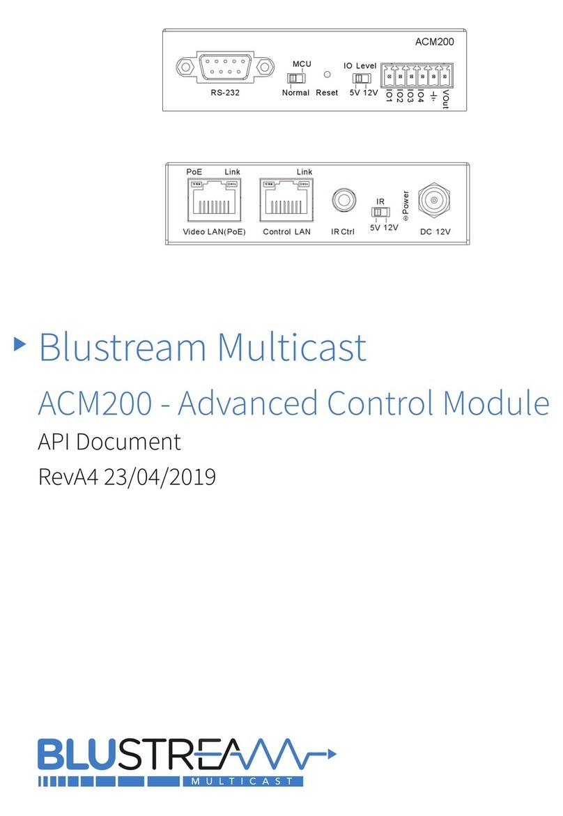
RS-232 NORMAL RESET 5V 12V
IO1
IO2
IO3
IO4
V OUT
IO LEVELMCU
ACM210
VIDEO LAN (PoE) CONTROL LAN IR CTRL
IR
5V 12V
LINKLINKPoE
12V 1A

ACM - Multicast Advanced Control Module USER MANUAL
02 www.blustream.co.uk / www.blustream.com.au / www.blustream-us.com
Surge protection device
recommended
This product contains sensitive electrical
components that may be damaged
by electrical spikes, surges, electric
shock, lightning strikes, etc. Use of
surge protection systems are highly
recommended in order to protect and
extend the life of your equipment.
Safety and performance notice
Do not substitute or use any other power
supply other than approved PoE network
products or approved Blustream power
supplies.
Do not disassemble the ACM200 unit
for any reason. Doing so will void the
manufacturer’s warranty.
Contents
Thank you for purchasing
this Blustream product
For optimum performance and safety,
please read these instructions carefully
before connecting, operating or adjusting
this product. Please keep this manual for
future reference.
Introduction 03
Features 03
Panel Descriptions - ACM200 / ACM210 04
Control Ports 05
Control Ports - IR Control 06
Network Connection - Schematic Diagram 07
Web-GUI - Sign In / Log In 08
Web-GUI - New Project Set-up Wizard 09 - 13
Web-GUI - Menu Overview 14
Web-GUI - Drag & Drop Control 15
Web-GUI - Video Wall Control 16
Web-GUI - Preview 17
Web-GUI - Project Summary 18
Web-GUI - Transmitters 19 - 21
Web-GUI - Receivers 22 - 23
Web-GUI - Fixed Signal Routing 24 - 26
Web-GUI - Video Wall Configuration 27 - 32
Web-GUI - Users 33 - 34
Web-GUI - Settings 35 - 36
Web-GUI - Update Firmware 37 - 39
Web-GUI - Update Admin Password 39
RS-232 Serial Routing 40
Specifications, Package Contents & Maintenance 41
Blustream IR, RS-232 & Telnet Commands 42 - 48
Troubleshooting 49
Computer Settings - enabling TFTP & Telnet 50 - 53

03
contact support@blustream.co.uk / support@blustream.com.au / support@blustream-us.com
ACM - Multicast Advanced Control Module USER MANUAL
Introduction
Impotant Note:
The Blustream Multicast system distributes HDMI video over managed network hardware. It is advised that Blustream
Multicast products are connected on an independent network switch (or VLAN) to prevent unnecessary interference, or
reduction in signal performance due to other network products bandwidth requirements.
Please read and understand the instructions in this manual and ensure that the network switch is configured correctly
prior to connecting any Blustream Multicast products. Failure to do so will result in problems with configuration of the
system and video performance.
• Web interface module for configuration and control of the Blustream Multicast system
• Intuitive 'Drag & Drop' source selection with video preview feature for active monitoring of system status
• Advanced signal management for independent routing of Video, Audio, IR, RS-232, and USB/KVM
• Auto system configuration
• 2x RJ45 LAN connections to bridge existing network to Multicast video distribution network, resulting in:
- Better system performance as network traic is separated
- No advanced network setup required
- Independent IP address per LAN connection
- Allows simplified TCP/IP control of Multicast system
• RS-232 integration for control of Multicast system
• IR integration for control of Multicast system
• PoE (Power over Ethernet) to power ACM from PoE switch
• Local 12V power supply (optional) should switch not support PoE
• Support for iOS and Android App control
• 3rd party drivers available for most control brands
The UHD Multicast distribution platform allows distribution of HDMI video over a 1Gb Network switch. The ACM200 &
ACM210 Advanced Control Modules (known as 'ACM' from this point forwards in this guide) allow advanced third party
control of the Multicast system using TCP / IP, RS-232 and IR.
The ACM includes a web interface module for control and configuration of the Multicast system and features 'Drag &
Drop' source selection with media preview and independent routing of Video, Audio, IR, RS-232, and USB / KVM.
Pre-built Blustream product drivers simplify Multicast product installation and negate the need for an understanding
of complex network infrastructures.
This User Guide covers the features and functionality for both the ACM200 and ACM210 Advanced Control Module
products from Blustream.
The ACM200 is currently used for IP50HD, IP200UHD and IP250UHD systems only.
The ACM210 can be used for individual IP50HD, IP200UHD, IP250UHD, IP300UHD and IP350UHD systems.
Please note: IP200UHD and IP250UHD systems are interoperable. IP300UHD and IP350UHD systems are interoperable.
The IP50HD is a standalone system and is not interoperabel with eithe rof the above 2 sets of Multciast systems.
Features

ACM - Multicast Advanced Control Module USER MANUAL
04 www.blustream.co.uk / www.blustream.com.au / www.blustream-us.com
VIDEO LAN (PoE) CONTROL LAN IR CTRL
IR
5V 12V
LINKLINKPoE
12V 1A
Front Panel
2
14
9
8
7
6
1RS-232 control port – connect to a third party control
device for control of the Multicast system using RS-
232.
2MCU Upgrade toggle - use when upgrading MCU
firmware only. Leave in normal position for
standard operation.
3Reset - short press resets the ACM, long press (10
seconds) factory defaults the ACM.
4IO Level switch - reserved for future use.
5IO Level phoenix - reserved for future use.
6Video LAN (PoE) - connect to the network switch that
the Blustream Multicast components are connected
to.
7Control LAN port - connect to existing network that
a third party control system resides on. The Control
LAN port is used for Telnet/IP control of the Multicast
system. Not PoE.
8IR Ctrl (IR input) – 3.5mm stereo jack. Connect to
third party control system if using IR as the chosen
method of controlling the Multicast system. When
using the included 3.5mm stereo to mono cable,
ensure the cable direction is correct.
9IR - adjust IR voltage level between 5V or 12V input
for IR Ctrl.
qPower LED indicator
wPower port – use 12V 1A DC adaptor (sold separately)
if not using a PoE network switch.
Rear Panel
Panel Descriptions - ACM200 & ACM210
5
11
3
10
RS-232 NORMAL RESET 5V 12V
IO1
IO2
IO3
IO4
V OUT
IO LEVELMCU
ACM210

05
contact support@blustream.co.uk / support@blustream.com.au / support@blustream-us.com
ACM - Multicast Advanced Control Module USER MANUAL
The ACM communication ports are located on both end panels and include the following connections:
Connections:
A. TCP/IP – for Multicast system control (RJ45 connector)
B. Infrared (IR) Input* - 3.5mm stereo jack - for Multicast I/O switching control only
C. RS-232 – for Multicast system control / RS-232 pass-through (DB9)
* Please note: the ACM200 can be used with both 5V and 12V IR line systems. Please ensure that the switch (adjacent
to the IR port) is correctly selected to the specification of the IR line input from the control system.
TCP/IP:
The Blustream ACM can be controlled via TCP/IP. For the full list of protocols please see the separate ‘API Commands’
document which can be downloaded from the Blustream website. A ‘straight-through’ RJ45 patch lead should be used
when connected to a network switch.
Control Port: 23
Default IP: 192.168.0.225
Default Username: admin
Default Password: 1 2 3 4
Please note: at the first log-in to the ACM, a new password will be required to be entered. It is not possible to reset this
without resetting the ACM unit. Please ensure the new password is noted down and kept for future reference.
RS-232 / Serial:
The ACM can be controlled via serial using the DB9 connector. Default settings below. For the full list of protocols
please see the separate ‘API Commands’ document which can be downloaded from the Blustream website.
Baud Rate: 57600
Data Bit: 8-bit
Parity: None
Stop Bit: 1-bit
Flow Control: None
The baud rate for the ACM can be adjusted using the web-GUI, or by issuing the following command via RS-232 or
Telnet: RSB x : Set RS-232 Baud Rate to Xbps
Where X= 0 : 115200
1 : 57600
2 : 38400
3 : 19200
4 : 9600
ACM Control Ports
AC
B
RS-232 NORMAL RESET 5V 12V
IO1
IO2
IO3
IO4
V OUT
IO LEVELMCU
ACM210
VIDEO LAN (PoE) CONTROL LAN IR CTRL
IR
5V 12V
LINKLINKPoE
12V 1A

ACM - Multicast Advanced Control Module USER MANUAL
06 www.blustream.co.uk / www.blustream.com.au / www.blustream-us.com
VIDEO LAN (PoE) CONTROL LAN IR CTRL
IR
5V 12V
LINKLINKPoE
12V 1A
The Multicast system can be controlled using local IR control from a third party control system. Source selection is
the only feature available when using local IR control - advanced features of the ACM such as video wall mode, audio
embedding etc. can only be achieved using RS-232 or TCP/IP control.
Blustream have created 16x input & 16x output IR commands allowing source selection of up to 16x Multicast
Transmitters on up to 16x Multicast Receivers. For systems larger than 16x source devices, RS-232 or TCP/IP control
will be required.
ACM Control Ports - IR Control
Link
RXTX CH Select
IR IR
Rx Tx Gnd
RS-232 CH
IP100UHD-RXMULTICAST UHD
1 2 3 4
41 42 43 44
45 46 47 48
49 50 51 52
53 54 55 56
57 58 59 60
61 62 63 64
65 66 67 68
69 70 71 72
73 74 75 76
77 78 79 80
5 6 7 8
9 10 11 12
13 14 15 16
17 18 19 20
21 22 23 24
25 26 27 28
29 30 31 32
33 34 35 36
37 38 39 40
MULTICAST
IR Receiver - IRR - stereo 3.5mm jack (optional)
Blustream 5V IR receiver to receive an IR signal and distribute
through Blustream products
Wiring pin - IR-CAB - stereo 3.5mm jack:
Signal
5V
Ground
The ACM is compatible with both 5V and 12V IR equipment. When the ACM is being used to receive an IR input into the
IR CTRL port, the adjacent switch must be toggled correctly to suit the IR voltage line of the chosen control system
before connection.
Please note: supplied Blustream IR cabling is all 5V
Third Party Control System
(source selection only)
3.5mm Stereo to Mono Cable - IR-CAB (included)
Blustream IR Control cable 3.5mm Mono to 3.5mm Stereo for
linking third party control solutions to Blustream products.
Compatible with 12V IR third party products.
Please note: Cable is directional as indicated
Wiring pin - IR-CAB - mono 3.5mm jack:
Signal
Ground

07
contact support@blustream.co.uk / support@blustream.com.au / support@blustream-us.com
ACM - Multicast Advanced Control Module USER MANUAL
ACM Network Connection
The ACM acts as a bridge between the control network and video network to ensure that the data travelling between
the two networks are not mixed. The ACM must be connected via CAT cable in accordance with typical networking
requirements.
Example Schematic
EX40B-Kit
RS-232
LAN Cable
IR Cable
Example Schematic
ACM200
IO Level
Reset
VOut
IO4
IO3
IO2
IO1
5VNormal
RS-232
MCU
12V
ACM200
Video LAN(PoE) Control LAN IR Ctrl
IR
5V 12V DC 12V
Power
Link Link
PoE
Yellow Green Yellow Green
Reserved for future update
Control Processor
Optional 12V PSU
where no PoE is available
Multicast UHD
Network Switch
Customer Home / Business
Network Switch
1G Managed Network Switch
1G Managed Network Switch

ACM - Multicast Advanced Control Module USER MANUAL
08 www.blustream.co.uk / www.blustream.com.au / www.blustream-us.com
Web-GUI Guide
The web-GUI of the ACM allows for full configuration of a new system, as well as ongoing maintenance and control of
an existing system through a web portal.
The ACM can (eventually) be accessed on any internet connected device including: tablets, smart phones and laptops
that are on the same 'Control' network. The ACM is shipped with a static IP address (as below), and is not set with
DHCP enabled.
Sign In / Log In
We would recommend that a computer / laptop is connected directly to the Control port of the ACM for the initial
configuraiton of a new system. As noted previously, the ACM is shipped with a static IP address, not HDCP. There are
instructions of how to amend the static IP address of a computer / laptop towards the rear of this manual.
To log in, open a web browser (i.e. Safari, Firefox, MS Edge etc.) and navigate to the default static IP address of the ACM
which is:
192.168.0.225
The sign in page is presented on connection to the ACM. The default admin password is: 1 2 3 4
The ACM requires a new password to be set for the Administrator on first log-in. It is not possible to reset this without
resetting the ACM unit. Please ensure the new password is noted down and kept for future reference. Once the new
password has been created, the ACM will require this once further to log-into the administration menu of the unit.

09
contact support@blustream.co.uk / support@blustream.com.au / support@blustream-us.com
ACM - Multicast Advanced Control Module USER MANUAL
On first log in of the ACM, a Set-up Wizard for configuring all components of the Multicast system will be presented.
This has been designed to speed up new system configuration as all default / new Multicast Transmitters & Receivers
can be connected to the network switch at the same time, whilst not resulting in an IP conflict during the system
configuration. This results in a system in which all components are automatically and sequentially assigned a name
and IP address ready for basic system use.
New Project Set-up Wizard
The ACM Set-up Wizard can be cancelled by clicking 'Close'. Please be aware that the system will not be configured
at this point, but can be continued by visiting the 'Project' menu. If a Project File is already available (i.e. replacing an
ACM on an existing site), this can be imported by using the saved .json file by clicking 'Import Project'.
Click 'Next' to continue set-up:
If at this point the chosen Network hardware is not configured for use with a Blustream Multicast system, click on the
hyperlink 'network switch setup guides' to navigate to a centralised webpage containing common Network Switch
Guides.
An example schematic diagram for the connections of the ACM can be accessed by clicking the hyperlink marked
'diagram'. This will ensure the ACM is connected correctly to the wider Multicast system before the Set-up Wizard
begins. Once the connections of the ACM are confirmed, click 'Next'.

ACM - Multicast Advanced Control Module USER MANUAL
10 www.blustream.co.uk / www.blustream.com.au / www.blustream-us.com
New Project Set-up Wizard - continued...
During normal use, the ACM will poll for status updates and screen-grabs of the media travelling through the system.
The polling of this information constantly has an aect with larger systems (75+ end points). The next stage of the
configuration is to pre-define the size of project. The options here are:
0-75 Products
75+ Products
This setting can be adjusted in the future should the system size increase.
Click on the relevant button to select the system size:

11
contact support@blustream.co.uk / support@blustream.com.au / support@blustream-us.com
ACM - Multicast Advanced Control Module USER MANUAL
New Project Set-up Wizard - continued...
There are two methods for adding new Transmitter and Receiver devices to a system:
Method 1: connect ALL Transmitter and Receiver units to the network switch. This method will quickly configure all
devices with their own individual IP addresses based on the following:
Transmitters:
The first Transmitter will be assigned an IP address of 169.254.3.1. The next Transmitter will be assigned an IP
address of 169.254.3.2, and so on....
Once the IP range of 169.254.3.x is filled (254 units), the soware will auto assign an IP address of 169.254.4.1,
and so on...
Once the IP range of 169.254.4.x is filled the soware will auto assign an IP address of 169.254.5.1, and so on
until 169.254.4.254
Receivers:
The first Receiver will be assigned the IP address of 169.254.6.1. The next Receiver will be assigned an IP
address of 169.254.6.2, and so on....
Once the IP range of 169.254.6.x is filled (254 units) the soware will auto assign an IP address of 169.254.7.1,
and so on...
Once the IP range of 169.254.7.x is filled the soware will auto assign an IP address of 169.254.8.1, and so on
until 169.254.8.254
Once complete, devices will need to be identified manually - this method will auto-assign product IP addresses and
ID's to each device connected to the network switch randomly (not by switch port).
Method 2: connect each Blustream Multicast Transmitter and Receiver to the network one-by-one. The Set-up
Wizard will configure the units sequentially as they are connected / found. This method allows for the control of
the sequential assigning of IP addresses and ID's of each product - the Transmitter / Receiver units can therefore be
labelled accordingly.
HDCP Mode: Blustream Multicast Receivers will automatically add HDCP onto the outgoing stream (regardless of whether the
source device has HDCP encoded onto its outgoing stream). The HDCP Mode selection buttons allow for HDCP to be forced or
follow a common compliance. When using commercial equipment where there is no HDCP, and capture soware is being used,
we would recommend setting the system to 'Bypass'.

ACM - Multicast Advanced Control Module USER MANUAL
12 www.blustream.co.uk / www.blustream.com.au / www.blustream-us.com
Once the set-up method to configure the system has been chosen, hit the 'Start Scan' button.
The ACM will search for new Blustream Multicast units on the network, and will continue to search for new devices
until such time as:
- The green 'Stop Scan' button is pressed
- The blue 'Next' button is pressed to progress the Set-up Wizard once all units have been found
New Project Set-up Wizard - continued...
As new units are found by the ACM, the units will populate to the relevant columns marked Transmitters or Receivers.
It is recommended to label the individual units at this point.
The Multicast units will be configured with the new IP address information at this point, and will reboot automatically.
Once all units have been found and configured, click 'Stop Scan', then 'Next'.

13
contact support@blustream.co.uk / support@blustream.com.au / support@blustream-us.com
ACM - Multicast Advanced Control Module USER MANUAL
New Project Set-up Wizard - continued...
The Device Set-up page allows for Transmitters and Receivers to be named accordingly. EDID and Scaler settings
for the individual Transmitters or Receivers can be set as required. For help with EDID and Scaler settings, click the
relevant buttons marked 'EDID Help' or 'Scaling Help'.
Features of the Device Set-up page include:
1. Name of Devices - during configuration the Transmitters / Receivers are automatically assigned default names
i.e. Transmitter 001 etc. Transmitter / Receiver names can be amended by typing in the corresponding box.
2. EDID - fix the EDID value for each Transmitter (source). This is used to request specific video and audio resolutions
for the source device to output. Basic help with EDID selection can be obtained by clicking the button marked
'EDID Help'. Please note, the default EDID for Blustream equipment is: 1080p, 2ch audio.
3. View (transmitters only) - opens the following pop-up:
This pop-up shows an image preview of the media currently being accepted by the Transmitter unit for naming
purposes. The ability to also identify the unit by flashing the front panel Power LED on the unit, and the ability to
Reboot the unit will all assist with the indentification of the unit for naming purposes.

ACM - Multicast Advanced Control Module USER MANUAL
14 www.blustream.co.uk / www.blustream.com.au / www.blustream-us.com
New Project Set-up Wizard - continued...
4. Scaler - adjust the output resolution using the built-in video scaler of the Multicast Receiver. The Scaler is capable
of both upscaling and downscaling the incoming video signal.
5. Actions - opens the following pop-up:
By default, during configuration, an OSD will appear on all screens connected to Receiver units for simple identification
of Receivers. The ability to also identify individual units by flashing the front panel Power LED's, and the ability to
Reboot the unit is contained here.
7. Turn OSD O / On - toggles the product ID onto all connected screens / displays (on by default during
configuration - the OSD will turn o automatically as the wizard progresses).
8. Next - continues to the Set-up Wizard Completion page
The Wizard Completion page finalises the basic configuration process, providing commonly used links for advanced
set-up options for Video Walls (not available for IP50HD systems), Fixed Signal Routing (IR, RS-232, Audio etc), and the
ability to back-up to a configuration file (recommended).
Click 'Finish' once completed to continue to the 'Drag & Drop Control' page.

15
contact support@blustream.co.uk / support@blustream.com.au / support@blustream-us.com
ACM - Multicast Advanced Control Module USER MANUAL
Web-GUI - Menu Overview
The 'User Interface' menu gives a guest user the ability to switch and preview the Multicast system without allowing
access to any settings that can amend the overall infrastructure of the system.
1. Drag & Drop Control - control of source selection for each Receiver including image preview of source devices
2. Video Wall Control - control of source selection for video wall arrays, including image preview of source devices
3. Preview - show the active video stream from any connected Transmitter and/or Receiver
4. Project - view or configure a new or existing Blustream Multicast system
5. Transmitters - summary of all Transmitters installed, with options for EDID management, checking FW version,
updating settings, adding new TX’s, replacing or rebooting products
6. Receivers - summary of all Receivers installed, with options for resolution output (HDR / scaling), function (video
wall mode / matrix), updating settings, adding new RX’s, replacing or rebooting products
7. Fixed Signal Routing - configure independent routing of Video, Audio, IR, Serial, USB, or CEC signals
8. Video Wall Configuration - set-up and configuration of Receivers to create a video wall array of up to a size of 9x9,
including: bezel / gap compensation, stretch / fit, and rotation. (Please note: video walls are not supported with
IP50HD systems).
9. Users - set-up or manage users of the system
10. Settings - system settings including: network credentials, clearing project, and resetting the ACM
11. Update Devices - apply the latest firmware updates to the ACM, and connected Transmiters / Receivers
12. Update Password - update Administrator password credentials for access to the ACM web-GUI
13. Log Out - log out the current User / Administrator
1. Drag & Drop Control - control of source selection for each Multicast Receiver including image preview of source
devices throughout the system
2. Video Wall Control - used for ‘Drag & Drop’ control of source selection for video wall arrays within the system,
including image preview of source devices throughout. Menu item only available where a video wall has been
configured within the system
3. Log In - used to log into the system as a User, or Administrator
The Administrator menu is accessed from a single password as set during initial set up. This menu allows for a
Multicast system to be completely configured, with access to all settings and features of the system.
Please note: it is not recommended to leave Administrator access or the Administrator password with an end user.

ACM - Multicast Advanced Control Module USER MANUAL
16 www.blustream.co.uk / www.blustream.com.au / www.blustream-us.com
Web-GUI - Drag & Drop Control
The Drag & Drop Control page is used to quickly and intuitively change a source input (Transmitter) for each (or
All) display (Receiver). The naming convention of the Transmitters and Receivers will be updated as per the names
assigned during configuration, or as have been updated in the Transmitter or Receiver pages.
Once the system has been fully configured the Drag & Drop Control page will show all online Transmitter and Receiver
products. All Multicast products will display the active stream from the device, which refreshes every few seconds.
Due to the size of the display window on certain phones, tablets or laptops, should the number of Transmitters and
Receivers be larger than the size available on screen, the User is given the ability to scroll / swipe through available
devices (le to right).
To switch sources, click on the required source / Transmitter, and drag the preview onto the required Receiver preview.
The Receiver preview window will update with the stream of the source selected.
The Drag & Drop switch will amend the Video/Audio stream from Transmitter to Receiver, but not Fixed Routing of
control signals.
Should ‘No Signal’ be displayed in the Transmitter preview window, please check the HDMI source device is powered
on, outputting a signal, and is connected via HDMI cable to the Transmitter. Check also the EDID settings of the
Transmitter device are applicable with the source being used.
Should ‘No Signal’ be displayed inside the Receiver preview window, check the unit is connected and powered from
the network (switch), and has a valid connection to a working Transmitter unit.
Should ‘No Display’ be shown inside the Receiver preview window, check the connected display is powered and has a
valid HDMI connection to the Receiver.
There is an 'All Receivers' window located on the le of the Receivers window. Dragging and dropping a Transmitter
onto this window will change the routing for ALL Receivers within the system to watch the source selected. Should the
preview of this window show the Blustream logo, this signifies that there is a mixture of sources being watched across
the Receivers within the system. The note underneath 'All Receivers' will display: 'TX: Dierent' to signify this.
Please note: the Drag & Drop Control page is also the home page for an active Guest user of the Multicast system -
only sources that the Guest or User have permission to view will be visible.
Receivers in Video Wall Mode are not displayed on the Drag & Drop page.

17
contact support@blustream.co.uk / support@blustream.com.au / support@blustream-us.com
ACM - Multicast Advanced Control Module USER MANUAL
Web-GUI - Video Wall Control
To assist wth simplified Video Wall switching control, there is a separate Video Wall Drag & Drop Control page. This
menu option is only available once a Video Wall has been configured within the ACM / Multicast system.
The source (Transmitter) preview windows are shown at the top of the page with the graphical representation of
the Video Wall displayed below. To switch the Video Wall array from one source to another, Drag & Drop the source
preview window onto the Video Wall preview underneath. This will switch all connected screens within the Video
Wall (within a group within a Video Wall only) to the same source / Transmitter in the Configuration that is currently
selected (in a group). Or Drag & Drop a Transmitter preview onto a 'Single' screen when the Video Wall array is in an
individual screen configuration.
Blustream Multicast systems can have multiple Video Walls (IP2xxUHD, or IP3xxUHD systems only). Selecting a
dierent Video Wall array, or to deploy a pre-defined Configuration / preset for each Video Wall can be carried out by
using the drop down boxes above the graphical representation of the Video Wall. This graphical representation will
automatically update as you select a dierent Video Wall or Configuration.
Should a screen within a Video Wall display on the GUI show 'RX Not Assigned', this means that the Video Wall does
not have a Receiver unit assigned to the array. Please revert back to the Video Wall set up to assign the Receiver
accordingly.
For the advanced API commands for control of Video Wall arrays within a system, please refer to the API Command
document available to download from the Blustream website.

ACM - Multicast Advanced Control Module USER MANUAL
18 www.blustream.co.uk / www.blustream.com.au / www.blustream-us.com
Web-GUI - Preview
The Preview feature is a quick way to view the media being streamed through the Multicast system once configured.
Preview the stream from any HDMI source device into the Multicast Transmitter, or the stream being received by
any Receiver in the system concurrently. This is particularly helpful for debugging and checking source devices are
powered on, and outputting a HDMI signal, or to check the I/O status of the system:
The Preview windows show a screen grab of the media which automatically updates every few seconds. To select the
Transmitter or Receiver to preview, use the drop down box to select the individual Transmitter or Receiver to preview.

19
contact support@blustream.co.uk / support@blustream.com.au / support@blustream-us.com
ACM - Multicast Advanced Control Module USER MANUAL
Web-GUI - Project Summary
Overview of the units that are currently set-up in the Multicast system, or for scanning the network for new devices to
assign to the system:
Options on this page include:
1. System Size: toggle between: 0-75 Products, and 75+ Products.
2. Toggle OSD: turn On / O the OSD (On Screen Display). Toggling the OSD On shows the ID number (i.e. ID 001) of
the Multicast Receiver on each display as an overlay to the media being distributed. Toggling OSD O removes the
OSD.
3. Export Project: create a save file (.json) for the current configuration of the system.
4. Import Project: import an already configured project into the current system. This is particularly helpful when
setting up a secondary system or expansion to a current system o-site where the two systems can be merged into
one.
5. Clear Project: clears the current project.
6. Assign New Devices: assign devices found in the Unassigned Devices section (at the bottom of this page) to the
current system
7. Continuously Scan & Auto Assign: continuously scan the network and auto assign new Multicast devices to the
next available ID and IP address as connected. If only connecting ONE new unit, use the 'Scan Once' option - the
ACM will continue to scan the network for new Multicast devices until found, or select this button again to stop the
scan.
8. Scan Once: scan the network once for any new Multicast devices connected, and then be presented with a pop
up to either manually assign the new device, or auto assign a new unit to the next available ID and IP address as
connected.

ACM - Multicast Advanced Control Module USER MANUAL
20 www.blustream.co.uk / www.blustream.com.au / www.blustream-us.com
Web-GUI - Transmitters
The Transmitter summary page is an overview of all Transmitter devices that have been configured within the system,
with the ability to update the system as required.
Features of the Transmitter summary page include:
1. ID - the ID (input) number is used for control of the Multicast system when using third party control platforms.
2. Name - the name assigned to the Transmitter (typically the device attached to the Transmitter).
3. IP Address - the IP address assigned to the Transmitter during configuration.
4. MAC Address - shows the MAC address of the Transmitter (LAN 1 port).
5. Dante MAC - shows the MAC address of the LAN2 port where independent Dante connectivity is being used. Please
see the button marked LAN2 Mode Help for further explanation on segregating Video and Dante networks.
6. Product - identifies the product in use that is connected to the system.
7. Firmware - firmware version currently loaded onto the Transmitter. For more information on firmware updating,
please see 'Update Firmware' section.
8. Status - shows the Online / Oline status of each Transmitter. Should a product show as 'Oline', check the units
connectivity to the network switch, speed of connection to the network.
9. EDID - fix the EDID value for each Transmitter (source). This is used to request specific video and audio resolutions
for the source device to output. Basic help can be obtained on EDID selection by clicking the button at the top of
the page marked 'EDID Help'. The available EDID selections used for IP50HD, IP2xxUHD, and IP3xxUHD systems all
dier.
10. HDMI Audio - selects either original HDMI audio, or replaces the embedded audio with a local analogue audio
input on the Transmitter. Default setting will be ‘Auto’.
11. LAN2 Mode: where IP250UHD or IP350UHD are being used, the option to separate the Dante audio for connectivity
to a separate Dante network is controlled from here. Where IP200UHD or IP300UHD are being used, this option is
not selectable. See table below for LAN selection.
12. Actions - opens a pop-up window with advanced configuration settings. See following page for further
information.
13. Refresh - refresh all current information on the devices within the system.
Other manuals for Multicast ACM200
2
This manual suits for next models
1
Table of contents
Other Blu Stream Control Unit manuals
Popular Control Unit manuals by other brands
IFM Electronic
IFM Electronic AS-i AirBox 32 installation instructions

Texas Instruments
Texas Instruments THS7001 user guide

Elkron
Elkron MP 110 manual

Dataq Instruments
Dataq Instruments DI-151RS DI-195B user manual
Teknoware
Teknoware W010007 installation guide
auto maskin
auto maskin DCU 305 R2 user manual
