Blue Coat SG510 Series User manual

Blue Coat®Systems
SG510 Series
Installation Guide
Version: SGOS 4.2.x and 5.1.x

P/N 231-02833 Blue Coat SG510 Installation Guide page ii
Contact Information
Blue Coat Systems Inc.
420 North Mary Ave
Sunnyvale, CA 94085-4121
http://www.bluecoat.com/support/index.html
bcs.info@bluecoat.com
suppor[email protected]
http://www.bluecoat.com
Copyright© 1999-2007 Blue Coat Systems, Inc. All rights reserved worldwide. No part of this
document may be reproduced by any means nor modified, decompiled, disassembled, published or
distributed, in whole or in part, or translated to any electronic medium or other means without the
written consent of Blue Coat Systems, Inc. All right, title and interest in and to the Software and
documentation are and shall remain the exclusive property of Blue Coat Systems, Inc. and its licensors.
ProxySG™, ProxyAV™, CacheOS™, SGOS™, Spyware Interceptor™, Scope™, RA Connector™, RA
Manager™, Remote Access™ are trademarks of Blue Coat Systems, Inc. and CacheFlow®, Blue Coat®,
Accelerating The Internet®, WinProxy®, AccessNow®, Ositis®, Powering Internet Management®,
The Ultimate Internet Sharing Solution®, Permeo®, Permeo Technologies, Inc.®, and the Permeo logo
are registered trademarks of Blue Coat Systems, Inc. All other trademarks contained in this document
and in the Software are the property of their respective owners.
BLUE COAT SYSTEMS, INC. DISCLAIMS ALL WARRANTIES, CONDITIONS OR OTHER TERMS,
EXPRESS OR IMPLIED, STATUTORY OR OTHERWISE, ON SOFTWARE AND DOCUMENTATION
FURNISHED HEREUNDER INCLUDING WITHOUT LIMITATION THE WARRANTIES OF
DESIGN, MERCHANTABILITY OR FITNESS FOR A PARTICULAR PURPOSE AND
NONINFRINGEMENT. IN NO EVENT SHALL BLUE COAT SYSTEMS, INC., ITS SUPPLIERS OR
ITS LICENSORS BE LIABLE FOR ANY DAMAGES, WHETHER ARISING IN TORT, CONTRACT OR
ANY OTHER LEGAL THEORY EVEN IF BLUE COAT SYSTEMS, INC. HAS BEEN ADVISED OF
THE POSSIBILITY OF SUCH DAMAGES.
Document Number: 231-02833
Document Revision: A.0 July 2006

P/N 231-02833 Blue Coat SG510 Installation Guide page iii
Contents
Chapter 1: Unpack and Rack a Blue Coat SG510
Unpacking a SG510................................................................................................... 8
SG510 Front Panel Features..................................................................................... 8
SG510 Back Panel Features...................................................................................... 9
Mounting the SG510 in an Equipment Rack....................................................... 10
Rack-Mounting Notes ......................................................................................... 10
Attaching the Cable Management Support......................................................... 11
Installing the Disk Drives ...................................................................................... 12
Connecting the Cables............................................................................................ 16
Powering On the SG510 ......................................................................................... 16
Power LED ............................................................................................................ 16
Chapter 2: Configure a SG510
Overview of First-Time Configuration................................................................ 19
Section A: Configuring the SG510 with the Front Panel Features
LCD Behavior .......................................................................................................... 21
System LCD and Modes......................................................................................... 22
SG510 Control Buttons ........................................................................................... 24
Using the Front Panel to Configure Basic Network Settings............................ 25
Section B: Placing the SG510 into the Network
Section C: Initial Configuration with a Web Browser
Requirements........................................................................................................... 29
Where to go next ..................................................................................................... 30
Section D: Initial Configuration Using a Direct Serial Port Connection
Section E: Configuring the SG510 from a Remote Location

P/N 231-02833 Blue Coat SG510 Installation Guide page iv
Step One—Enter the Remote Configuration Parameters Using a Web
Browser............................................................................ 55
Step Two—Complete the Configuration .......................................................... 59
Section F: Logging on to the SG510
Logging on to the SG510 Management Console ............................................. 62
Logging on to the SG510 CLI ............................................................................. 64
Section G: Configuring a Front-Panel PIN
Section H: Configuring the Front-Panel LCD Behavior
Chapter 3: Removing and Installing Disk Drives
Removing a Disk Drive.......................................................................................... 72
Installing a New Disk Drive.................................................................................. 73
Chapter 4: Option Cards
Dual Gigabit Ethernet 1000B-SX (optical) Card............................................... 75
Dual Gigabit Ethernet (copper) Pass-Through Card ...................................... 75
SSL Accelerator Card........................................................................................... 75
Chapter 5: Troubleshooting
The SG510 does not power up .............................................................................. 77
The Initial Configuration Page is Not Accessible............................................... 78
Creating A Static Route to the SG510................................................................... 79
You cannot access the serial console.................................................................... 79
You cannot access the Management Console ..................................................... 79
A Security Warning Appears for the Initial Configuration Web Page ........... 80
The SG510 certificate is no longer valid .............................................................. 80
Resetting the SG510 to Factory Defaults.............................................................. 81
The SG510 Does Not Come Back Up After Rebooting ...................................... 83
Appendix A: Specifications
General Specifications ............................................................................................ 85

P/N 231-02833 Blue Coat SG510 Installation Guide page v
Environmental Specifications................................................................................ 86
Appendix B: Regulatory Statements
General System Cautions....................................................................................... 87
Power Cord Cautions ............................................................................................. 87
Class A Digital Warning ........................................................................................ 88
Advertencia Digital Clase A.................................................................................. 88
EC Community EMC Warning............................................................................. 88
Advertencia EMC de la Comunidad EC ............................................................. 88
Canadian EC EMC Warning ................................................................................. 88
Australia/New Zealand EC EMC Warning........................................................ 89
Taiwan BSMI Notification ..................................................................................... 89
Japan VCCI EMC Notification .............................................................................. 89
Battery Warning Notification................................................................................ 89
Chinese Battery Warning Notification................................................................. 90
China CCC Notification ......................................................................................... 90
Lasers ........................................................................................................................ 90
Declaration of Conformity..................................................................................... 94
Appendix C: Apéndice C: Declaraciones Regulatorias
Precauciones generales del sistema...................................................................... 95
Conexión del cable de alimentación..................................................................... 95
Lasers ........................................................................................................................ 96
Appendix D: Anhang D: Regulierende Anweisungen
Allgemeine Systemvorsichtsmassnahmen.......................................................... 97
Anschliessen des Stromkabels .............................................................................. 97
Lasers ........................................................................................................................ 98
Appendix E: Simplified Chinese Regulatory Statements


P/N 231-02833 Blue Coat SG510 Installation Guide page 7
Chapter 1: Unpack and Rack a Blue Coat SG510
This installation guide provides general instructions for installing, configuring, and
using the Blue Coat SG510.
This chapter explains how to unpack the SG510, install it in an equipment rack,
insert the disk drives, connect the cables, and power it on.
After you have completed the first-time configuration of the SG510 and have
logged in, you should do the following:
•Upgrade the SG510 software by downloading the latest patch release
(available at http://download.bluecoat.com).
•Fully configure the appliance.
To configure the SG510, you will need to download the Blue Coat ProxySG
Configuration and Management Guide Suite, (the CMG) available on the Blue
Coat Web site at www.bluecoat.com. (Look for WebPower Login under
Support.)
You can also find tech briefs (technical briefs) on the Blue Coat Web site.
If you log on to the SG510 using a Web browser, you can access the online help by
clicking the Help button on the Management Console screens. The Management
Console is the graphical user interface for the SG510.
See “Logging on to the SG510” on page 62 for more information.
Important: Follow all warnings and instructions marked on the product and
included in this manual.
P/N 231-02833 Blue Coat SG510 Installation Guide page 8
Unpacking a SG510
When you receive and unpack the SG510, verify that the package contains the
following items:
SG510 Front Panel Features
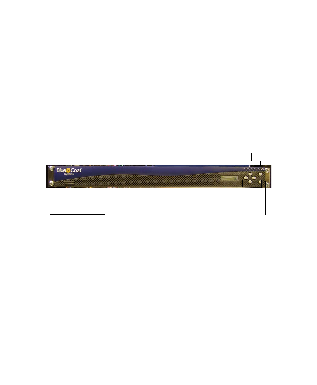
The figure below shows the front of a SG510.
Figure 1-1: The Front of a SG510
The SG510 front panel has the following features:
•An LCD and six control buttons to monitor activity and configure basic
networking settings.
•Power, Disk Drive, and LAN LEDs.
•A front panel that pivots downward and pulls outward giving you access to
up to two disk drives.
•Mounting brackets that extend from each end of the chassis to secure a SG510
to an equipment rack.
• Blue Coat SG510 Series Appliance • AC Power cord
• Quick Start Guide • Disk drives (up to two)
• Null-modem serial cable • Cable Management Support
• License, Warranty, and Safety
information
Power, Disk
Drive, and LAN
LEDs
Control
buttons
LCD
Plates that attach
to the front of the
equipment rack
Front
panel

P/N 231-02833 Blue Coat SG510 Installation Guide page 9
You can mount a SG510 in a standard mounting rack. See “Mounting the SG510 in
an Equipment Rack” on page 10 for rack mounting instructions.
SG510 Back Panel Features
The figure below shows the back of a SG510.
Figure 1-2: The Back of a SG510
The following features are located on the back of the SG510:
•An AC power connector.
•Two USB (Universal Serial Bus) ports.
•A serial port to connect to a PC, to a serial terminal, or to a stand-alone serial
console terminal.
•Two full-duplex, auto-sensing Ethernet network adapter ports supporting
10/100/1000 Base-T connections.
•An expansion slot for optional network, bridging, or SSL cards. See Chapter 4:
’Option Cards" for more information about SG510 option cards.
AC Power
Connector
Ethernet
Adapter
Ports
Serial
Port
USB
Ports Expansion Slot for
SSL or Bridge Card

P/N 231-02833 Blue Coat SG510 Installation Guide page 10
Mounting the SG510 in an Equipment Rack
The Blue Coat SG510 is designed to fit into a standard telco-style or four-post
cabinet style equipment rack.
The SG510 ships with the rack-mounting ears installed.
Rack-Mounting Notes
Read these notes before rack-mounting the SG510.
•Elevated Operating Temperature—If installed in a closed or multi-unit rack
assembly, the operating ambient temperature of the rack environment may be
greater than the ambient room temperature. Therefore, consideration should
be given to installing the equipment in an environment compatible with the
maximum ambient temperature specified by the manufacturer.
•Reduced Air Flow—Installation of the equipment in a rack should be such
that the amount of air flow required for safe operation of the equipment is not
compromised.
•Mechanical Loading—Mounting of the equipment in the rack should be such
that a hazardous condition is not achieved due to uneven mechanical loading.
•Circuit Overloading—Consideration should be given to the connection of the
equipment to the supply circuit and the effect that overloading of the circuits
might have on overcurrent protection and supply wiring. Appropriate
consideration of equipment nameplate ratings should be used when
addressing this concern.
•Earthing (Grounding)—Reliable earthing of rack-mounted equipment should
be maintained. Particular attention should be given to supply connections
other than direct connections to the branch circuit (for example, use of power
strips).
Attach the SG510 to the equipment mounting rack:
1Position the SG510 into the equipment rack so that the ears of the brackets
align with the holes in the front of the rack.
2Use equipment-rack screws to mount the SG510 to the equipment rack.
Figure 1-3 shows a SG510 flush-mounted on a Telco equipment rack.

P/N 231-02833 Blue Coat SG510 Installation Guide page 11
Figure 1-3: SG510 Attached to a Telco Equipment Rack
Attaching the Cable Management Support
The cable management support routes network serial cables to avoid tangling.
Fasten the cable management support to the back of the system as follows:
1Position the cable management support at the back of the system on the right;
secure it with a 6-32 x 1/4 flathead screw at the side.
Figure 1-4: Attach the Cable Management Support
When you attach cables to the system, run them through this clip to keep
them from tangling.
Use equipment-rack screws
to attach to the SG510 to the
rack
Attach the cable
management support with a
flathead screw

P/N 231-02833 Blue Coat SG510 Installation Guide page 12
Installing the Disk Drives
The following instructions are for a first-time installation of the disk drives that
are shipped with the SG510. The drive slots on each end of the appliance contain
non-removable, blank disk-drive spacers.
Figure 1-5: Disk-Drive Slot Arrangement
Important: You cannot hot-swap disks in the SG510; you will lose all
configuration settings.
Drive slot 2
Non-removable
spacer Drive slot 1 Non-removable
spacer
P/N 231-02833 Blue Coat SG510 Installation Guide page 13
Important: The SG510 ships with two disk-drive spacers already installed in
the drive slots at each end of the system. Do not attempt to
remove these blank drive spacers. If you ordered only a single
disk drive, the unit ships with a third disk-drive spacer installed
in Slot 2.
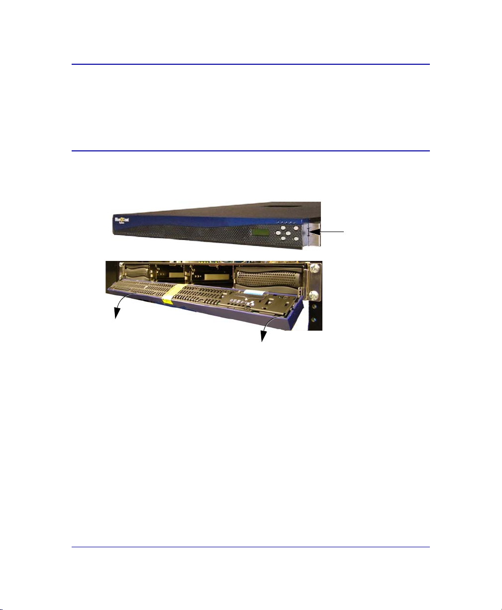
1Press the push tabs on each side of the front-panel bezel to release the locked
position of the front panel. Pull the front panel forward and down.
Figure 1-6: Access the Disk Drive Slots
Press the push
tabs on each side
of the front-panel
bezel
The front panel
swings forward
and down

P/N 231-02833 Blue Coat SG510 Installation Guide page 14
If other equipment blocks the front panel from opening all the way, you can
pull the front panel forward, sliding out the front-panel tray until you can
access the disk drives.
Figure 1-7: Access the Disk Drive Slots
2Position the disk-drive carrier upright, so that the disk-drive button appears
on the right; press this button to release the disk-drive lever.
Figure 1-8: Release the Disk-Drive Lever
3Use the lever to slide the disk-drive carrier into the first open slot (Slot 1,
second from left).
Important: Always insert disk drives from left to right. If you have
only one disk drive, install it into drive Slot 1.
Pull out the front-panel tray, if necessary, to access the disk drives
Press the
disk-drive
button
Thedisk-drivelever
is released

P/N 231-02833 Blue Coat SG510 Installation Guide page 15
Figure 1-9: Insert the Disk-Drive Carrier
4When the disk-drive carrier meets the SG510 frame, gently push the lever in
towards the button until the handle latches on the button.
5Repeat steps 2 to 4 to install the optional disk drive in drive slot 2.
Note: If you need to remove a drive, press the button on the right
side of the disk-drive carrier to release the lever. Pull the
lever towards you to slide the carrier out of the slot.
Drive Slot 1

P/N 231-02833 Blue Coat SG510 Installation Guide page 16
Connecting the Cables
Connect the network cables, serial cable, and AC power cord.
Figure 1-10: Connect the Cables to the Back of the System
1Plug the network cable into adapter 0. Plug a second cable into the other
adapter if desired.
The two full-duplex, auto-sensing Ethernet network adapters supporting
10/100/1000 Base-T connections are labeled 0 and 1.
2Plug the serial cable into the serial connector, if necessary.
If you attach the serial cable, you can connect the system to a PC, serial
terminal, or stand-alone Serial Console box.
3Plug the enclosed power cord into the power cord receptacle.
Powering On the SG510
1After you have connected the power cord to the rear of the system, plug the
other end of the power cord into a power receptacle.
2Verify that the system has powered on successfully. See the four system states
described below and the corresponding states of the Power LED.
Power LED
•No color: the SG510 is powered off or non-functional
Ethernet adapter
ports (Ports 0 and 1)
Serial port
AC Power
P/N 231-02833 Blue Coat SG510 Installation Guide page 17
•Solid Amber: the SG510 is powered on but unable to perform tasks (for
example, while booting up)
•Flashing Green to Amber: the SG510 is powered on but is not configured
•Green: the SG510 is powered on and at least minimally configured
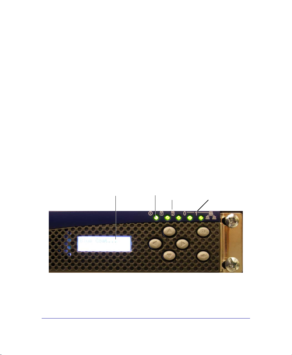
3The three steps below show a typical, first-time, start-up sequence.
•The Power LED lights up and the LCD becomes green and displays the
name Blue Coat.
•The Power LED starts of solid amber and then begins flashing green and
amber.
•After a moment, the disk drive LEDs corresponding to the disk drives
that are installed light up.
•If you are connected to the network, the LAN LEDs light up.
•The LCD displays IP address not configured (if a first-time configuration
has not been done) or it cycles between CPU utilization and the
hostname.
Figure 1-11: Verify Successful Power On
The SG510 comes with all software installed. To configure a SG510 for the first
time go to “Configure a SG510” on page 19.
Power
LED Disk Drive
LEDs (2)
LCD LAN status
LEDs (2)

P/N 231-02833 Blue Coat SG510 Installation Guide page 18

P/N 231-02833 Blue Coat SG510 Installation Guide page 19
Chapter 2: Configure a SG510
You need to configure a SG510 the first time you power it on to set the basic
network parameters and to make sure that the SG510 hardware and software are
working properly.
Overview of First-Time Configuration
There are four ways to configure a SG510 the first time you power it on. Each of
these methods of configuring a SG510 let you make the basic network settings
required to test the connection and functionality.
Configuration
Method Description
Front Panel Use the front-panel LCD and buttons.
(This is the quickest and easiest way to do a first-time configuration.
To use the front panel method, go to “Configuring the SG510 with
the Front Panel Features” on page 21.
Serial Console Use a direct connection between the system and a PC, or a serial
terminal, or a stand-alone serial console terminal.
To use the serial console connection, go to “Initial Configuration
Using a Direct Serial Port Connection” on page 38.
Web Browser Use a Web browser. To use this method for SGOS 5.1.1.x and later,
you must first configure the IP address of the SG510 using the serial
console or front panel. Blue Coat recommends using the Web
browser configuration method if you are running SGOS 5.1.1.x or
later.
To use the Web browser configuration method, go to “Initial
Configuration with a Web Browser” on page 29.

P/N 231-02833 Blue Coat SG510 Installation Guide page 20
After you complete the first-time configuration, you must log on to the system
and use the command-line interface (CLI) or the Management Console graphical
user interface to fully configure the system. First-time configuration is designed
only to make sure that the SG510 hardware and software are working properly.
See “Logging on to the SG510” on page 62 for more information.
Refer to the Blue Coat ProxySG Configuration and Management Guide Suite for
information on how to fully configure the software. Download the Blue Coat
ProxySG Configuration and Management Guide Suite, available on the Blue Coat
Web site at www.bluecoat.com. (Look for WebPower Login under Support.)
Remote
Configuration
You can use this method if your appliance is running SGOS 4.2.2.x or
later. The remote configuration method is not supported for
appliances running 5.1.1.x or later.
Use two people to remotely configure the appliance—one who
enters the configuration parameters from a remote location and
another who places the SG510 into the network and finalizes the
configuration by clicking a generated URL.
To use the remote configuration method, go to “Configuring the
SG510 from a Remote Location” on page 55.
Configuration
Method Description
Table of contents
Other Blue Coat Network Hardware manuals


Popular Network Hardware manuals by other brands

SonicWALL
SonicWALL 1RK38-0C8 Safety and Regulatory Reference Guide

HP
HP HPE Synergy 12000 Frame Setup and installation guide

Siemens
Siemens SCALANCE W788-1PRO operating instructions

Cradlepoint
Cradlepoint AER2200 Series quick start guide

Wisenet
Wisenet XRN-815S user manual

Sencore
Sencore VB330-SW user manual


