Autometers Systems ADP3-80C User manual

Digitale 3-Phasen Power Meter
Direktanschluß bis 80 A - Wandlerstromanschluß für .../5 A bis 10.000/5 A
WAR U G
Die Installation muß von einer Elektrofachkraft oder unter deren Leitung und Aufsicht
durchgeführt und geprüft werden.
Bei Arbeiten am Meßgerät, etzspannung abschalten!
Bedienungsanleitung
IIST036-01 Stand 07-09-2010
Die Power Meter dienen zur Messung wichtiger
Parameter wie I, U, PF, F sowie aller Leistungen je Phase
auf einem Blick; Übersicht der gelierferten, bzw.
abgegebener Energie.
Kode Beschreibung
ADP3-80C Digitaler 3-Phasen Power Meter für Direktanschluß
0.25-5 (80) A - 1 Tarif - 2 S0
(für seitliche IR Kommunikation eingerichtet)
ADP3-5C Digitaler 3-Phasen Power Meter für Wandlerstromanschluß
... /5 A bis 10.000/5 A - 0.05-5 (6) A - 1 Tarif - 2 S0
(für seitliche IR Kommunikation eingerichtet)
DEUTSCH E GLISH
Three-phase Digital Power Meter
Direct connection 80 A - Connection through CT .../5 A till 10.000/5 A
WAR I G
Installation must be carried out and inspected by a specialist or under his supervision.
When working on the instrument, switch off the mains voltage!
Operating instructions
The Power Meter offers important measurements
parameter like I, U, PF, F and all power parameters
monitoring all three phases in one time, export and
import energy register are available.
Code Description
ADP3-80C
three-phase digital power meter for direct connection
0.25-5 (80) A - 1 tarif - 2 S0
(set up for side IR communication)
ADP3-5C
three phase digital power meter with connection
by CT .../5 A, up to 10.000/5 A - 0.05-5 (6) A - 1 tarif - 2 S0
(set up for side IR communication)
Einstellung der Meßwerte / Measurements
Valori misurati / Valeurs mesurées - Start Up
OK
Phasenströme - Rückbeleuchtung aus
Line currents Backlight OFF
Correnti di Fase - Display spento
Courants de Phase - Display éteint
Phasenströme - Rückbeleuchtung ein
Line currents Backlight O
Correnti di Fase - Display acceso
Courants de Phase - Display allumé
Jede Taste drücken
Any Key pushing
Qualunque tasto
Quelconque touche
V-L/
V-L/L
PF-L
W-L
Q-L
S-L
⌺F (Hz)
⌺Wh
import
⌺Wh
export
Taste als 2 Sek. drücken um Parameter zu ändern
To change the parameter push for more than 2 sec.
Per modificare i parametri premere per più di 2 sec.
Pour charger le paramètre presser pour plus de 2 sec.
Einstellung der Parameter (password unfähig)
Parameter-Password disabled (OFF)
Parametri-Password disabilitata (OFF) / Réglage des paramètres (OFF) - Start Up
OK
Seitenwahl
Page selection
Selezione di pagina
Sélection de page
OK
+
-
OK
Löschen / Cancel / Annulla / Annulation
Bestätigen / Confirm / Conferma / Confirmez
Seitenwahl
Page selection
Selezione di pagina
Sélection de page
Bestätigen / Confirm / Conferma / Confirmez

ITALIA O
Power Meter Digitale Trifase
Connessione diretta 80 A - Connessione a mezzo TA .../5 A fino 10.000 A
FRA ÇAIS
Power Meter Digital Triphasé
Connexion directe
80 A -
Connexion à
TC .../5 A jusqu'à 10.000 A
ATTE ZIO E
L’installazione deve essere effettuata e verificata dauno specialista
o sotto la sua supervisione.
Togliere tensione prima di intervenire sull’apparecchio.
Istruzioni di servizio
Lo strumento Power Meter serve per la misura di
parametri importanti come I, U, PF, F e potenze per ogni
fase in unica visione; lettura dell’energia attiva
fornita e consumata.
Codice Descrizione
ADP3-80C
power meter digitale trifase connessione
diretta 0.25-5 (80) A - 1 tariffa - 2 S0
(laterare IR predisposto per la comunicazione)
ADP3-5C
power meter digitale trifase connessione a mezzo TA .../5 A
fino a 10.000/5 A - 0.05-5 (6) A - 1 tariffa - 2 S0
(laterare IR predisposto per la comunicazione)
ATTE TIO
L’installation doit être effectuée et contrôlée par unspécialiste ou
bien sous sa supervision.
Débrancher les différents branchements au secteur avant d'intervenir sur l'appareil!
Mode d’emploi
L'indicateur Power Meter propose des mesures de
paramètres importants comme I, U, PF, F et tous les
paramètres du pouvoir de contrôle des trois phases en
unseule fois, l'exportation et l'importation enregistrer
aucune énergie sont disponibles.
Code Description
ADP3-80C
power meter triphasé pour connexion directe 0.25-5 (80) A
1 tarifs - 2 S0 (établi pour la communication IR latérale)
ADP3-5C
power meter triphasé pour connexion à l'aide de TC .../5 A
jusqu'à 10.000/5 A - 0.05-5 (6) A - 1 tarifs - 2 S0
(établi pour la communication IR latérale)
OK
+
-
OK
Löschen / Cancel / Annulla / Annulation
Bestätigen / Confirm / Conferma / Confirmez
Seitenwahl
Page selection
Selezione di pagina
Sélection de page
OK
+
-
OK
Löschen / Cancel / Annulla / Annulation
Bestätigen / Confirm / Conferma / Confirmez
Seitenwahl
Page selection
Selezione di pagina
Sélection de page
OK
Löschen / Cancel / Annulla / Annulation
Bestätigen / Confirm / Conferma / Confirmez
OK
Löschen / Cancel / Annulla / Annulation
Bestätigen / Confirm / Conferma / Confirmez
OK
Löschen / Cancel / Annulla / Annulation
Bestätigen / Confirm / Conferma / Confirmez
OK
Seitenwahl
Page selection
Selezione di pagina
Sélection de page
OK
Löschen / Cancel / Annulla / Annulation
Bestätigen / Confirm / Conferma / Confirmez
+
-
OK
Löschen / Cancel / Annulla / Annulation
Bestätigen / Confirm / Conferma / Confirmez
Taste als 2 Sek. drücken um Parameter zu ändern
To change the parameter push for more than 2 sec.
Per modificare i parametri premere per più di 2 sec.
Pour charger le paramètre presser pour plus de 2 sec.
Einstellung der Parameter (password befähit)
Parameter-Password enabled (O )
Parametri-Password abilitata (O ) / Réglage des paramètres (O ) - Set Up

15.5
2 Nm
80 A Direktanschluss Hauptklemmen -
Schraubendreher PZ2
80 A direct connection main terminals -
Screw driver PZ2
80 A connessione diretta morsetti principali -
Cacciavite PZ2
80 A connexion directe bornes principales -
Tournevis PZ2
5 A Wandleranschluss Hauptklemmen
-
Schraubendreher PZ1
5 A CT connection main terminals
-
Screw driver PZ1
5 A connessione TA morsetti principali
-
Cacciavite PZ1
5 A connexion TA bornes principales
-
Tournevis PZ1
Kabel-Abisolierlänge und Max Drehmoment
Cable stripping length and max terminal screw torque
Lunghezza di spelatura dei fili e coppia massima di serraggio
Longueur de dénudage des fils et couple de serrage maximum
14
1.5 Nm
Tarif-und Datenübertragungsklemmen - Schraubendreher Klinge 0.8x3.5 mm
Tariff and communication terminals - Screw driver blade 0.8x3.5 mm
Morsetti tariffe e comunicazioni - Cacciavite a taglio 0.8x3.5 mm
Bornes tarifs et communications - Tournevis a corta 0.8x3.5 mm
9
0.5 Nm
Maße / Dimension
Dimensioni / Dimensions
OK
Taste als 4 Sek. drücken um den Hinweis
zulöschen
Pushing for more than 4 sec. the signal
is diasabled
Premendo per più di 4 sec.
la segnalazione è disattivata
Pressant pour plus que 4 sec. la
signalisation est désactivée
OK
OK
OK
OK
OK
Beide Tasten gleichzeitigdrücken / Push Both
Premere Entrambi / Presser Tous les deux >4 Sek./sec.
Löschen / Cancel / Annulla / Annulation
Bestätigen / Confirm / Conferma / Confirmez
}
+
-
OK
Löschen / Cancel / Annulla / Annulation
Bestätigen / Confirm / Conferma / Confirmez
Seitenwahl
Page selection
Selezione di pagina
Sélection de page
ach 60 Sek. Tasten inaktivitat muß die Password erneut eingegeben werden
After 60 sec. of inactivity reenter the password
Dopo 60 sec. di inattività reinserire la password
Après 60 sec. d’inactivité réinsérer le password
S0 Impulse für kWh / S0 Pulses for kWh / S0 Impulsi per kWh / S0 impulsion en kWh
(immer auf 16,6 Hz begrenzt) / (always limited to 16.6 Hz) / (sempre limitata a 16,6 Hz) / (toujours limitées à 16,6 Hz)
For 80 A model, the available range is 1 ... 500 pulses/kWh
For xx/5A, the available range depends on external CT, as follows:
Für 80 A-Modell wird der verfügbare Bereich 1 ... 500 Imp./kWh
Für xx/5A, hängt die verfügbare Bandbreite ab, laut externen CT, wie folgt:
Per il modello 80 A, la gamma disponibile è di 1 ... 500 impulsi/kWh
Per il modello xx/5A, la gamma disponibile dipende dal TA esterno, come segue:
Pour le modèle 80 A, la gamme disponible est de 1 ... 500 impulsions / kWh
Pour le modèle xx/5A, la gamme disponible dépend du TC externes, comme suit:
5
10
15 ... 30
35 ... 60
65 ... 120
125 ... 300
305 ... 600
605 ... 1200
1205 ... 3000
3005 ... 6000
6005 ... 10000
1 ... 10000
1 ... 5000
1 ... 2000
1 ... 1000
1 ... 500
1 ... 200
1 ... 100
1 ... 50
1 ... 20
1 ... 10
1 ... 5
CT - TA - TC
Bereich / Range / Portata / Portée
LED Impulse für kWh / LED Pulses for kWh / Impulsi LED per kWh / LED impulsion en kWh
(immer auf 50 Hz begrenzt) / (always limited to 50 Hz) / (sempre limitata a 50 Hz) / (toujours limitées à 50 Hz)
For 80 A model, the available range is 1 ... 2000 pulses/kWh
For xx/5A, the available range depends on external CT, as follows:
Für 80 A-Modell wird der verfügbare Bereich 1 ... 2000 Imp./kWh
Für xx/5A, hängt die verfügbare Bandbreite ab, laut externen CT, wie folgt:
Per il modello 80 A, la gamma disponibile è di 1 ... 2000 impulsi/kWh
Per il modello xx/5A, la gamma disponibile dipende dal TA esterno, come segue:
Pour le modèle 80 A, la gamme disponible est de 1 ... 2000 impulsions / kWh
Pour le modèle xx/5A, la gamme disponible dépend du TC externes, comme suit:
5 ... 15
20 ... 35
40 ... 90
95 ... 180
185 ... 360
365 ... 900
905 ... 1800
1805 ... 3600
3605 ... 9000
9005 ... 10000
1 ... 10000
1 ... 5000
1 ... 2000
1 ... 1000
1 ... 500
1 ... 200
1 ... 100
1 ... 50
1 ... 20
1 ... 10
CT - TA - TC
Bereich / Range / Portata / Portée
Power Meter
für Wandleranschluß
Power Meter with connection with CT
Power Meter con connessione a mezzo TA
Power Meter pour connexion à l’aide de TC
Anzeige bei Phasenausfall und falschen Phasensequenzanschluß
Phases Sequence Error Message / Messaggio Inversione di Fase
Message d’Erreur de Séquence des Phases

ADP3-80C
ADP3-80C
kWh
7
654
+--+
S0
kWh kWh
7
654
+--+
S0
kWh kWh
7
764
+--+
S0
kWh
ADP3-80C
Schaltbild / Wiring diagram
Schema di cablaggio / Schéma de câblage
direkt - direct - diret. - direc.
80 A
Wandler - CT - TA - TC
.../5 A
“Der -Leiter muß am Power-meter
angeschlossen werden” “Wire needs to be connected to the
Power-meter ” “Il eutro deve essere collegato al
Power-meter ” “Le conducteur doit être branché au
Power-meter ”
ADP3-5C
kWh
10
987
+--+
S0
kWh kWh
10
987
+--+
S0
kWh kWh
10
987
+--+
S0
kWh
ADP3-5C
ADP3-5C
“Der -Leiter muß am Power-meter
angeschlossen werden” “Wire needs to be connected to the
Power-meter ” “Il eutro deve essere collegato al
Power-meter ” “Le conducteur doit être branché au
Power-meter ”
Hinweis für den Anschluss von Wandlerzählern
Für den Leitungsschutz werden Absicherungen von 6 A empfohlen. Stromwandler dürfen nicht mit offenen lemmen betrieben werden, da gefährlich hohe Spannungen auftreten können.
Nichtbeachtung kann zu Personen- und Sachschäden führen. Außerdem können die Wandler thermisch überlastet werden.
Instructions for the connection of transformer counters
A fuse of 6 A is recommended for the line protection. Current transformers must not be operated with open terminals since dangerous high voltages might occur which may result in personal injuries
and property damage. In addition to this, the transformers are exposed to thermal overload.
Istruzioni per il collegamento dei TA
Per la protezione della linea si consiglia un fusibile da 6 A. I trasformatori di corrente non devono funzionare con i terminali/morsetti aperti, perché possono aversi delle tensioni pericolosamente elevate, che
possono provocare lesioni alle persone e danni alle cose. I trasformatori sono inoltre esposti al sovraccarico termico.
Instructions pour le branchement des TC
Pour la protection de la ligne, il est recommandé un fusible de 6 A. Les transformateurs de courant ne doivent pas fonctionner avec les bornes/plots ouverts en raison des tensions dangereusement élevées
qui pourraient rovoquer des lésions aux personnes ou des dommages aux choses. Les transformateurs peuvent par ailleurs être exposés à une surcharge thermique.

Bemerkung / ote / otas / otes

Caractéristiques techniques
Conforme aux normes EN 50470-1, EN 50470-3, EN 62053-23, EN 62053-31
Caractéristiques générales
• Boîtier DIN 43880
• Fixation EN 60715
• Profondeur
Fonctionnement
• Connexion à une charge en monophasé en triphasé (n° fils)
• Mémorisation de la configuration/donnees mémoire flash interne
• Indication tarif actuel pour énergie il active et réactive
Alimentation
• Tension nominale d'alimentation Un
• Domaine de variation
• Fréquence nominale fn
• Puissance absorbée (max. de phase) Pv
Surchargeabilité
• Tension Un permanent: phase/phase
1 sec.: phase/phase
permanent: phase/N
1 sec.: phase/N
• Courant Imax permanent
momentané (0,5 s)
momentané (10 ms)
Visualisation (lecture)
• Erreur de branchement et manque phase identifiable par l'indic. séquence phases
• Afficheur LED - Énergie
LED - Grandeur instantanées
dimension digit
• Énergie active: 1 indicateur, 8 chiffres 1 tarif
+ indication absorbée ou distribuée (flèche) flux le plus grand
• Puissance active instantanée: 1 indic., 3 chiffres
• Puissance réactive instantanée: 1 indic., 3 chiffres
• Puissance apparente instantanée: 1 indic., 3 chiffres
• Tarif actuel 1 indicateur, 1 chiffre
• Primaire du transform. de courant settaggio est impostabile à des pas de 5 A
• Cycle de visualisation
Précision
• Énergie et puissance actives conforme EN 50470-3
• Énergie et puissance réactive conforme EN 620053-23
Entrées de mesure
• Insertion
• Tension Un phase/phase
phase/N
• Domaine de tension phase/phase
phase/N
• Courant Iref
• Courant In
• Courant Imin
• Domaine de courant (Ist ... Imax) connexion directe
connexion TC .../5 A
• Transformateur de courant primaire
minimum imp.
• Fréquence
• Forme d’onde en entrée sinusoïdal
• Courant initial pour la mesure d'énergie (Ist)
Interface SO conforme EN 62053-31
• Sortie impulsion 1 sortie impulsion d'énergie à l'exportation
1 sortie d'impulsion des importations d'énergie
• Quantité impulsion connexion directe 80 A
con. TC .../5 A, sélection. automat. (vois tableau)
• Durée impulsion
• Tension nécessaire min ... max
• Courant permis impulsion ON (max 230 V a.c./d.c.)
• Courant permis imp. OFF (cour. de disper. max 230 V a.c./d.c.)
Sortie impulsion
• Calibrage frontal (contrôle de précision) LED
Interface IR latérales
• Pour le raccordement de moduls de communication
(LA -TCP/IP / M-Bus / Modbus RTU / RS-485 / K X-EIB / SD-Card Datalogger)
Sécurité selon les normes E 50470-1
• Installation pour intérieurs
• Degré de pollution
• Tension d'exercice
• Classe de protection (EN 50470)
• Épreuve tension d'impulsion
• Tension d'essai AC (EN 50470-3, 7.2)
• Résistance du boîtier à la flamme UL 94
Bornes de connecter
• Type cage borne courant principale tête de la vis Z +/-
• Type cage borne sortie impulsion tête de la vis à fente
• Type cage borne tension principale fil compact min. (max)
fil flexible avec cosse min. (max)
• Type cage borne sortie impulsion fil compact min. (max)
fil flexible avec cosse min. (max)
Conditions ambiantes
• Environnement mécanique
• Environnement électromagnétique
• Température d'utilisation
• Limite de la température d'emmagasinage et de transport
• Humidité relative (non condensé)
• Vibrations amplitude vibration sinusoïdale à 50 Hz
• Indice de protection appareil installé frontalement (bornes)
(*)Pour l'installation dans un coffret au moins avec la protection IP51
FRA ÇAIS

Technical data
Data in compliance with EN 50470-1, EN 50470-3, EN 62053-23, EN 62053-31
General characteristics
• Housing DIN 43880
• Mounting EN 60715
• Depth
Operating features
• Connection to single / three-phase load (n° wires)
• Storage of energy values and configuration internal flash memory
• Display tariffs identifier for active and reactive energy
Supply
• Rated supply voltage Un
• Operating range voltage
• Rated frequency fn
• Rated power dissipation (max. for phase) Pv
Overload capability
• Voltage Un continuous; phase/phase
1 second: phase/phase
continuous; phase/N
1 second: phase/N
• Current Imax continuous
momentary (0,5 s)
momentary (10 ms)
Display (readouts)
• Connection errors and phase out discernible from phase-sequence indic.
• Display type LCD - Energy
LCD - Largeness instantaneous
digit dimensions
• Active energy: 1 display, 8 digit 1 tariff
+ display import or export (arrow) overflow
• Instantaneous active power: 1 display, 3-digit
• Instantaneous reactive power: 1 display, 3-digit
• Instantaneous apparent power: 1 display, 3-digit
• Instantaneous tariff measurement 1 display, 1-digit
• Transformer primary current steps of 5 A
• Display period refresh
Measuring accuracy
• Active energy and power acc.to EN 50470-3
• Reactive energy and power acc.to EN 62053-23
Measuring input
• Type of connection
• Voltage Un phase/phase
phase/N
• Operating range voltage phase/phase
phase/N
• Current Iref
• Current In
• Current Imin
• Operating range current (Ist ... Imax) direct connection
transformer connection (CT)
• Transformer current primary current of the transformer
smallest input step adjus. in 5 A steps
• Frequency
• Input waveform sinusoidal
• Starting current for energy measurement (Ist)
Pulse output (SO) acc.to EN 62053-31
• 2 pulse ouput 1 pulse output energy export
1 pulse output energy import
• Quantity pulse output direct connection 80 A
connec. CT .../5 A, automat. adjus. (see table)
• Pulse duration
• Required voltage min ... max
• Permissible current pulse ON (max 230 V a.c./d.c.)
• Permissible current pulse OFF (leakage cur. max 230 V a.c./d.c.)
Optical interfaces
• Front side (accuracy control) LED
Lateral IR interfaces
• For communication moduls connection
(LA -TCP/IP / M-Bus / Modbus RTU / RS-485 / K X-EIB / SD-Card Datalogger)
Safety acc. to E 50470-1
• Indoor meter
• Degree of pollution
• Operational voltage
• Protective class (EN 50470)
• Impulse voltage test
• AC voltage test (EN 50470-3, 7.2)
• Housing material flame resistance UL 94
Connection terminals
• Type cage main current paths screw head Z +/-
• Type cage pulse output blade for slotted screw
• Terminal capacity main current paths solid wire min. (max)
stranded wire with sleeve min. (max)
•Terminal capacity pulse output solid wire min. (max)
stranded wire with sleeve min. (max)
Environmental conditions
• Mechanical environment
• Electromagnetic environment
• Operating temperature
• Limit temperature of transportation and storage
• Relative humidity (not condensation)
• Vibrations 50 Hz sinusoidal vibration amplitude
• Degree protection housing when mounted in front (terminal)
(*)For the installation in a cabinet at least with IP51 protection.
Dati tecnici
Secondo Norma EN 50470-1, EN 50470-3, EN 62053-23, EN 62053-31
Caratteristiche generali
• Custodia DIN 43880
• Fissaggio EN 60715
• Profondità
Funzionamento
• Connessione a un carico monofase / trifase (n° fili)
• Memorizzazione energia misurata e config. memoria flash interna
• Indicazione tariffa attuale per energia attiva e reattiva
Alimentazione
• Tensione nominale di alimentazione Un
• Campo di variazione tensione
• Frequenza nominale fn
• Potenza assorbita (max. per fase) Pv
Sovraccaricabilità
• Tensione Un permanente; fase/fase
1 secondo: fase/fase
permanente; fase/N
1 secondo: fase/N
• Corrente Imax permanente
momentanea (0,5 s)
momentanea (10 ms)
Visualizzazione (lettura)
• Errore di collegamento e mancanza fase riconoscibile dall’indicazione sequenza fasi
• Display LCD - Energia
LCD - Grandezze istantanee
dimensione digit
• Energia attiva: 1 indicatore, 8 cifre 1 tariffa
+ indicazione assorbita o erogata (freccia) flusso massimo
• Potenza attiva istantanea: 1 indicatore, 3 cifre
• Potenza reattiva istantanea: 1 indicatore, 3 cifre
• Potenza apparente istantanea: 1 indicatore, 3 cifre
• Tariffa attuale 1 indicatore, 1 cifra
• Trasformatore di corrente primaria
il settaggio è impostabile a passi da 5 A
• Ciclo di visualizzazione
Precisione
• Energia e potenza attiva secondo EN 50470-3
• Energia e potenza reattiva secondo EN 62053-23
Ingressi di misura
• Inserzione
• Tensione Un fase/fase
fase/N
• Campo di tensione fase/fase
fase/N
• Corrente Iref
• Corrente In
• Corrente Imin
• Campo di corrente (Ist ... Imax) connessione diretta
inserzione TA .../5 A
• Trasformatore di corrente primaria
minimo impostabile
• Frequenza
• Forma d’onda in ingresso sinusoidale
• Corrente iniziale per la misura di energia (Ist)
Interfaccia SO secondo EN 62053-31
• 2 uscite impulso 1 uscita impulso energia - export
1 uscita impulso energia - import
• Quantità impulso connessione diretta 80 A
connes. TA .../5 A, impost. automat. (vedi tabella)
• Durata impulso
• Tensione necessaria min ... max
• Corrente consentita impulso ON (max 230 V a.c./d.c.)
• Corrente consentita impulso OFF (cor. di disper. max 230 V a.c./d.c.)
Interfaccia ottica
• Calibratura frontale (controllo di precisione) LED
Interfaccia laterale IR
• Per il collegamento ai moduli di comunicazione
(LA -TCP/IP / M-Bus / Modbus RTU / RS-485 / K X-EIB / SD-Card Datalogger)
Sicurezza secondo E 50470-1
• Installazione per interni
• Classe inquinamento
• Tensione di funzionamento
• Classe di protezione (EN 50470)
• Prova tensione di impulso
• Prova a tensione AC (EN 50470-3, 7.2)
• Resistenza della custodia alla fiamma UL 94
Morsetti di connessione
• Tipo di gabbia morsetto corrente principale testa della vite Z +/-
• Tipo di gabbia morsetto uscita impulso testa della vite a taglio
• Capacità morsetto corrente principale filo compatto min. (max)
filo flessibile con capocorda min. (max)
• Capacità morsetto uscita impulso filo compatto min. (max)
filo flessibile con capocorda min. (max)
Condizioni ambientali
• Ambiente meccanico
• Ambiente elettromagnetico
• Temperatura d’impiego
• Limite della temperatura di immagazzinaggio e trasporto
• Umidità relativa (non condensata)
• Vibrazioni ampiezza vibrazioni sinusoidali 50 Hz
• Grado di protezione apparecchio montato frontalmente (morsetti)
(*)Grado di protezione garantito in un quadro con almeno grado di protezione IP51
ITALIA O E GLISH

Daten nach EN 50470-1, EN 50470-3, EN 62053-23, EN 62053-31 ADP3-80C ADP3-5C
Allgemeine Daten
• Gehäuse DIN 43880 DIN 4 Mod. 4 Mod.
• Befestigung EN 60715 35 mm DIN DIN
• Bauhöhe mm 70 70
Funktion
• Anschluß einphasige und dreiphasige Lasten n° Leiter 2-4 4
• Speicherung der Einstellung und Zählerstand Digitaldispaly interner Speicher - ja-yes-si-oui ja-yes-si-oui
• Tarife für Wirk-u. Blindenergie - T1 T1
Versorgung
• Bemessungssteuerspeisespannung Un V a.c. 230 230
• Spannungebereich V 184 ... 276 184 ... 276
• Bemessungsfrequenz fn Hz 50 50
• Bemessungsverlustleistung (max. für Phase) Pv VA (W) ⭐8 (0.6) ⭐8 (0.6)
Überlastbarkeit
• Spannung Un Dauerbetrieb: Phase/Phase V 480 480
1 Sekunde: Phase/Phase V 800 800
Dauerbetrieb: Phase/N V 276 276
1 Sekunde: Phase/N V 300 300
• Strom Imax Dauerbetrieb A 80 6
urzbetrieb für (0.5 s) A- 120
urzbetrieb für (10 ms) A 2400 -
Anzeige (Auslesung)
• Anschlußfehler und Phasenausfall Anzeige des Drehfeldfehlers - PHASE Err PHASE Err
• Anzeige LCD - Energie n° Digits 9 (1 ... 3 Dezimale-Dec.) 9 (1... 3 Dezimale-Dec.)
LCD - Blitzschneller Umfang n° Digits 4 (1 ... 3 Dezimale-Dec.) 4 (1... 3 Dezimale-Dec.)
Digit Abmessungen mm x mm 6.00 x 3 6.00 x 3
• Wirkenergie: 1 Anzeige, 8-stellig 1 Tarife Wh 0.01 0.01
+ Anzeige Bezug oder Lieferung (Pfeil) max Anzeige (Durchlauf) MWh 9999999.99 9999999.99
• Momentane Wirkleistung: 1 Anzeige, 3-stellig W, kW, MW 000 ... 999.9 000 ... 999.9
• Momentane Blindenergie: 1 Anzeige, 3-stellig var, kvar, Mvar 000 ... 999.9 000 ... 999.9
• Momentane Blindleistung: 1 Anzeige, 3-stellig VA, kVA, MVA 000 ... 999.9 000 ... 999.9
• Tariferkennung der Anzeige 1 Anzeige, 1-stellig - T1 T1
• Wandler Primärstrom in 5 A Schritte A- 5 ... 10.000
• Anzeigezyklus s1 1
Messgenauigkeit
• Wirkenergie und Wirkleistung nach EN 50470-3 lasse BB
• Blindenergie und Blindleistung nach EN 62053-23 lasse 22
Messeingang
• Anschlußart - direkt-direct-diret. Wandler-CT-TA-TC .../5 A
• Spannung Un Phase/Phase V 400 400
Phase/N V 230 230
• Arbeitsbereich Spannung Phase/Phase V 319 ... 480 319 ... 480
Phase/N V 184 ... 276 184 ... 276
• Strom Iref A5-
• Strom In A-5
• Strom Imin A 0.25 0.05
• Arbeitsbereich Strom (Ist ... Imax) Direktanschluss A 0.015 ... 80 -
Wandleranschluss A- 0.003 ... 6
• Wandlerstrom Primärstrom des Wandlers A- 5 ... 10.000
kleinster Eingabeschritt A - 5
• Frequenz Hz 50 50
• Eingangswelligkeitsform - sinusförmig sinusförmig
• Betriebsanlaufstrom (Ist) mA 15 3
S0 Schnittstellen nach EN 62053-31
• Impulsausgänge 1 Impulsausgang für Energie-Export - ja-yes-si-oui ja-yes-si-oui
1 Impulsausgang für Energie-Import - ja-yes-si-oui ja-yes-si-oui
• Impulsmenge bei 80 A Imp/kWh einstellbare, adjust., impostab. -
bei Wandler automatisch (siehe Tabelle) Imp/kWh - einstellbar (abhängig von der CT)
• Impulsdauer ms 30 ±2 ms 30 ±2 ms
• Erforderliche Spannung min ... max V a.c (d.c.) 5 ... 230 ±5% (5 ... 300) 5 ... 230 ±5% (5 ... 300)
• Zulässiger Strom Impuls ON (max 230 V a.c./d.c.) mA 90 90
• Erlaubter Strom Impuls OFF (Fehlerstrom max 230 V a.c./d.c.) µA 1 1
Optische Schnittstellen
• Frontseitige LED (zur Genauigkeitskontrolle) LED imp/kWh einstellbare, adjust., impostab. einstellbare, adjust., impostab.
IR-Schnittstellen
• Seitlich zur Anbindung von ommunikationsmodulen - ja-yes-si-oui ja-yes-si-oui
(LA -TCP/IP / M-Bus / Modbus RTU / RS-485 / K X-EIB / SD-Card Datalogger)
Sicherheit nach E 50470-1
• für Innenräume - ja-yes-si-oui ja-yes-si-oui
• Verschmutzungsgrad -2 2
• Betriebsspannung V 300 300
• Schutzklasse (EN 50470) lasse II II
• Prüfspannung 1.2/50 µs-kV 66
• AC voltage test (EN 50470-3, 7.2) kV 44
• Flammenwiderstand UL 94 lasse V0 V0
Klemmenanschlüsse
• Liftklemmen für Betriebs-und Hauptstrombahnen Schraubenkopf Z +/- POZIDRIV PZ2 PZ1
• Liftklemmen für S0 Impulsausgänge linge für Schlitzschraube mm 0.8 x 3.5 0.8 x 3.5
• lemmenkapazität Betriebs-und Hauptbahnen starr min. (max) mm21.5 (35) 1.5 (6)
flexibel, mit Hülse min. (max) mm21.5 (35) 1.5 (6)
• lemmenkapazität für S0 Impulsausgänge starr min. (max) mm20.14 (2.5) 0.14 (2.5)
flexibel, mit Hülse min. (max) mm20.14 (1.5) 0.14 (1.5)
Umweltbedingungen
• Mechanische Umgebung - M1 M1
• Elektromagnetische Umgebung - E2 E2
• Betriebstemperatur °C -10 ... +55 -10 ... +55
• Temperaturgrenzen für Lagerung und Transport °C -25 ... +70 -25 ... +70
• Relative Feuchte (ohne ondensation) % ⭐80 ⭐80
• Schwingen Sinus-Amplitude bei 50 Hz mm ±0.075 ±0.075
• Schutzart Eingebautes Gerät Frontseite/ lemmen - IP51(*)/IP20 IP51(*)/IP20
(*)Für die Installation in einem Verteiler mit mindestens IP51 Schutz.
DEUTSCH
Technische Daten
This manual suits for next models
1
Table of contents
Other Autometers Systems Measuring Instrument manuals
Autometers Systems
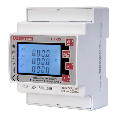
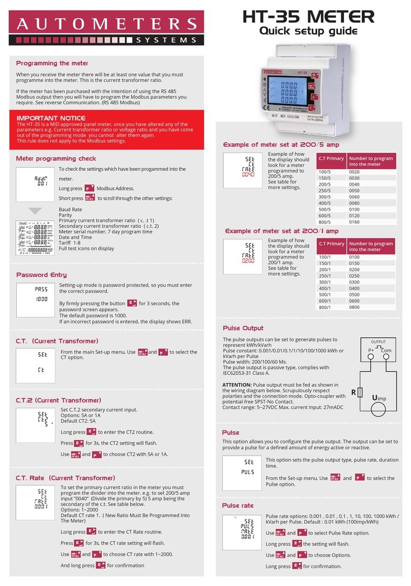
Autometers Systems HORIZON HT-35 User manual
Autometers Systems
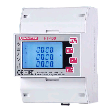
Autometers Systems HORIZON HT-400 User manual
Autometers Systems
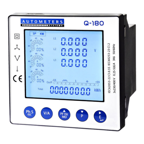
Autometers Systems Q-180 User manual

Autometers Systems
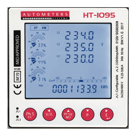
Autometers Systems HORIZON HT-1095 User manual
Autometers Systems
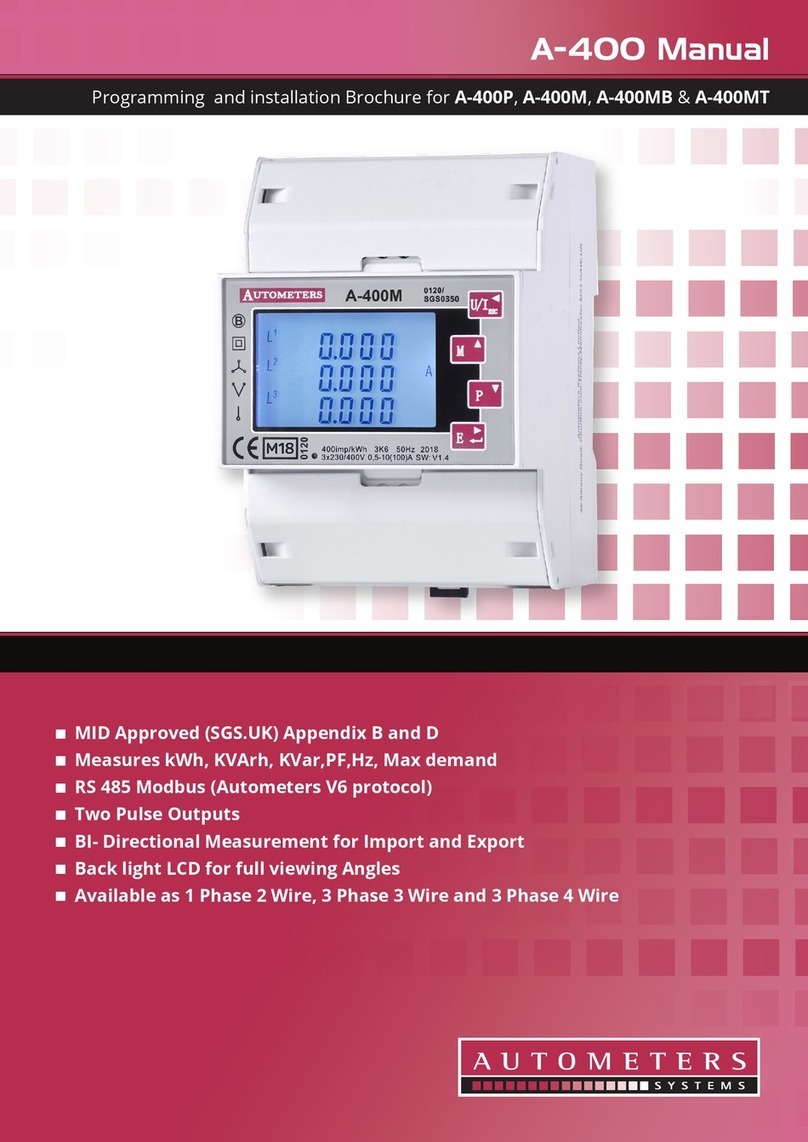
Autometers Systems A-400 Series User manual
Autometers Systems
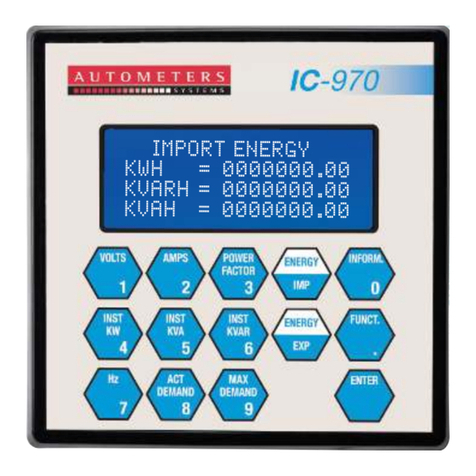
Autometers Systems IC 970 Installation instructions
Autometers Systems
Autometers Systems HORIZON HT-35 User manual
Autometers Systems
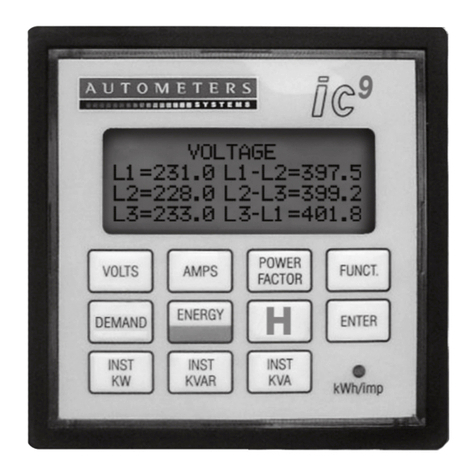
Autometers Systems ic9 User manual
Autometers Systems
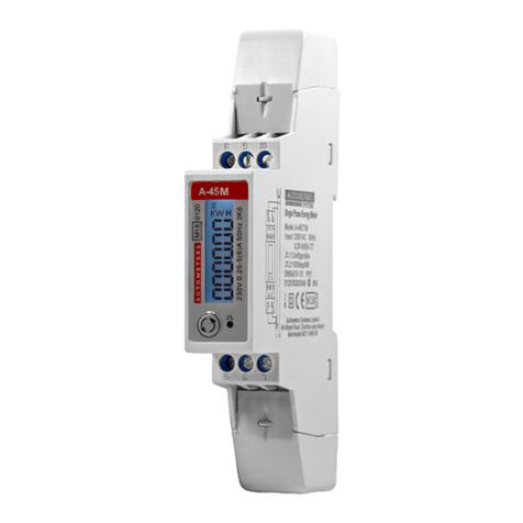
Autometers Systems A-45 Series User manual
Autometers Systems
Autometers Systems HORIZON HT-1095 User manual
