Blue Sea Systems M2 Vessel Systems Monitor User manual

M2 Vessel Systems Monitor (M2-VSM)
PN 1850
Installation Checklist
Check for components included
Read Warning and Cautions
Read QuickStart Installation Guide for mounting instructions
Read System Overview, Mounting Considerations, Detailed Wiring,
and Sensing Description
Read QuickStart Installation Guide for installation notes
Follow Initial System Setup instructions
CongureDisplays
CongureAlarms
Specications
Display Size 55mm x 28mm
Power Supply 7V–70V DC
Power Consumption 0.3W–1.0W*
NMEA2000LoadEquivalency 1
DC Voltage
Voltages 12V, 24V, 36V, 48V
Range 7V–70V DC
Resolution 0.01V DC
VoltageAccuracy +/-1%
DC Current
ShuntIncluded 1×PN8255(500A/50mV)
Range −500Ato500A
CurrentAccuracy +/-1%
Resolution(100to500) 1A
Resolution(0.0to99.9) 0.1A
AlarmActivation HighandLowVoltage,
HighCurrent,andLowBattery
AC Voltage
Range 50V–250VAC(RMS)
Resolution 1VAC
AC Current
Range 0Ato150A(300Aoptional)**
Resolution(100to150) 1A
Resolution(0.0to99.9) 0.1A
CurrentTransformer 1×PN8256(150A/50mA)
AlarmActivation HighandLowVoltage,Current,
andFrequency
Frequency
Range 40Hz–90Hz
Resolution 1Hz
Power
Range 0W–45kW
Resolution(0W–9990W) 10W
Resolution(10kW–45kW) 0.1kW
Tanks†
Alarm High/LowLevels
Senders NorthAmerican240Ω–33Ω
European 10Ω–180Ω
BlueSeaSystemsUltrasonic
Custom
SenderResolution 1%
CustomTankShapes AutoCalibration
AlarmNotication Runtimeperhour
Cyclesper24-hour
Cycle Counter
Regulatory
Monitor face is IP66 – protected against powerful water jets
when installed according to instructions
* Variablewithvoltage,displayintensity,andsleepmode
** Willachieve300AwithanoptionalcurrenttransformerPN1829
† Compatiblewithbilgemonitorswithexternaloatswitchesorwithautomatic
bilgeswitchesthatindicateonstatusviaa12Voutput.
Components Included
M2 Head Unit Surface Mount Gasket
Mounting Ring
Surface Mount Bezel
and Seal
Mounting Nut
Flat Mount Bezel
Screwdriver
Retail Package Only
Connectors
Bezel
Mount
Footer
Header
Carrier
Mount
#6-32 x 1/4"
Flat Head
Machine Screws
(4X)
#6-32 x 3/8"
Flat Head
Machine Screws
(4X)
Surface Mount Cover Flat Mount Clamp
Panel
Frame
PN 8255 Shunt (1X)
AC Current Transformer
8256
360 Panel Mounting Kit PN 1525 (sold separately)
1
Instructions

Resource Information
State-of-Charge(SOC)http://bluesea.com/viewresource/1324
ACCurrentMeasurementhttp://bluesea.com/viewresource/86
Warning and Caution Symbols
WARNING: The symbolreferstopossibleinjurytotheuserorsignicantdamagetothemeteriftheuserdoesnotfollowtheprocedures.
CAUTION: The symbolreferstorestrictionsandruleswithregardtopreventingdamagetothemeter.
WARNING
•VerifythatallACsourcesaredisconnectedbeforeconnectingordisconnectingthecurrenttransformer.Failuretodosowillgeneratelethalvoltages
on the current transformer.
•Ifyouarenotknowledgeableaboutelectricalsystems,haveanelectricalprofessionalinstallthisunit.Thediagramsintheseinstructionspertainto
the installation of M2 Digital Meters and not to the overall wiring of the vessel.
•Ifaninverterisinstalledonthevessel,itspowerleadsmustbedisconnectedatthebatterybeforethemeterisinstalled.
•IfanACgeneratorisinstalledonthevessel,itmustbestoppedandrenderedinoperablebeforethemeterisinstalled.
•VerifythatnootherDCorACsourcesareconnectedtothevessel’swiringbeforeinstallingthemeter.
CAUTION
• Thebackoftheunitisnotwaterproof.Donotinstallwherethebackofthemeterisexposedtowater.
Installation
1. TheM2VSMmustbeconnectedtoanon-switchedcircuittoensureaccurateandconsistentState-of-Chargemonitoring.
2.Makeallconnectionstothemeter’sterminalblockbeforeconnectingtheterminalblocktotheunit.
Keephandsawayfromtheterminalblockwhenapplyingpowertothemeter.
3.AsthenalDCconnection,insertafuseintothein-linefuseholderonthewiretothepositive(+)batteryterminal.
Mounting Templates
Flat Mount
3.34" (84.8mm)
3.00" (76.2mm)
3.00" (76.2mm)
3.34" (84.8mm)
Surface Mount
3.40" (86.5mm)
3.46" (87.9mm)
Ø2.125"
(54mm)
2

STEP 1
Panel
Frame
360 Panel
Mount
Carrier
Use 1/4"
Mounting
Screws
STEP 2
Footer
Panel
Frame
Bezel
Header
Snap header
and footer
into mounting
clips and post.
Snap the
mounting bezel
into place
with the flat
edge up.
STEP 3
Panel
Frame
BezelFooter
Header
M2
Head
Unit
Mounting
Ring and Nut
Mounting
Substrate
Clamp
Flat
Mount
Bezel
M2
Head
Unit
Mounting
Ring and Nut
Mounting
Substrate
M2
Head
Unit
Surface
Mount
Bezel
and Seal
Mounting
Ring and Nut
Surface
Mount
Gasket
Surface
Mount
Cover
NOTE: During
installation use cover
to align the bezel
and gasket
Flat Mount
Surface Mount
360 Panel Mount PN 1525
Mounting Considerations
M2DigitalMetershavethreemountingmethods:Surfacemount,Flatpanelmount,and360panelmount.Whensurfacemountedperinstructionsthe
unitfaceiswaterprooftoIP66.Flatpaneland360mountingsystemsarenotwaterproof.Theunitshouldnotbeatpanelor360mountedifusedinan
exposedlocation.Forallmountings,thebackoftheunitisnotwaterproofandmustbekeptdry.
3

Functions
DC Functions
• Monitorthevoltagesofuptotwobatterybanksandcurrentdrawononebatterybank.
• ProvidesbatteryState-of-Charge(SoC),capacity,amphours(Ah)remaining,andchargecycles.
AC Functions
• Monitorsthevoltages,currentdraws,frequency,andpowerofoneACsource.
Tank/Bilge Functions
• Monitoruptotwotanksorbilges
• ProvidesHigh/Lowlevelalarmsforeachtank
• Keepstrackoftotalbilgeruntimeinthelasthour
• Keepstrackofthetotalnumberofbilgecyclesinthelast24hours.
• Keepstrackoftheaveragenumberof24-hrbilgecyclesinthelastweek
• Keepstrackofthetotalnumberofbilgecycles
Connections
IMPORTANT! TheSensingDescriptionsectionofthismanualgivesimportantdetailstothelocationofsensorsintheACandDCelectrical
systemsoftheboat.Improperlocationandcongurationofsensorscanresultinerroneousreadingsandpossibledamagetocomponents.
Pin-out Table
Meter Power Supply Connections
Allmetersmusthavepins1(DCNeg.)and2(DCPos.)connected.Thesepinsareusedtoprovidepowertothemeter.Connectpin1togroundand
pin2toa12Vto48Vpowersource.Pin2isalsousedtomonitorthevoltagesonbank2.Thecurrentdrawfromthemeterislessthan50mA(typically
around20mAiftheback-lightisoff).Itwouldtakemorethan2monthstodraina100Ahbatteryto50%.Ifabatteryisgoingtobeleftunattendedfor
morethantwomonths,itisrecommendedtodisconnectthebatteryfromthemeter.
Detailed Wiring
4
Connector Pin Assignment Table
A. 2 Pin Connector* 3.5mm Function
1
2
1
2
1
2
Battery 1-
Battery 1+
AC Voltage - Neutral
AC Voltage - Hot
DC Negative required connection
DC Supply/Battery 2+ required connection
3Tank/Bilge 1
B. 2 Pin Connector** 5mm
C. 8 Pin Connector* 3.5mm
4
5
6
7
8
USB
M5
Tank/Bilge 2
DC Shunt 1–
DC Shunt 1+
AC Current Transformer – ***
AC Current Transformer + ***
USB Slave
NMEA 2000
* Supports wire sizes from 16-26 AWG
** Supports wire sizes from 12-24 AWG
*** Caution - Incorrect connections may damage the monitor
A B
AC NEUTRAL
AC HOT
Battery 1
Battery 2
Bilge
Tank
OR
NMEA
2000
To loads From Supply
Shunt
C
M5
USB
2 Bilges or
2 Tanks or
1 Bilge &
1 Tank
12345678
1212
Fuse
(5 Amp)
Fuse
(0.5 Amp)
Fuse
(5 Amp)

5
DC Connections
DC Current
TheM2VSMMetersrequiretheuseofashunt.ShuntsmustbeconnectedbetweenthenegativeterminalonBattery1andthemainnegativebus.Allloads
andchargesourcesshouldhavetheirnegativeterminalsonthemainnegativebus,withtheexceptionoftheM2negativesourcewhichmustbeconnected
directlytothebatterysideoftheshunt.ShuntsensewiresmustbeatwistedpairfromtheshunttotheM2MeterforpropercalculationofState-of-Charge
(SoC).Twistedpairwirecanbepurchasedfromelectricalsupplycompaniesormadebytwistingbyhandorwithanelectricdrillmotor.Thecurrent(Amper-
age)readingforBattery1shouldbenegativewhenitisnotbeingchargedandDCpowerisbeingused(loadsareactive).Ifnot,reversethetwistedpair
DC shunt sense leads.
ItispossibletoconnecttheDCshuntonthepositivesideofthecircuitwithaShuntShifter(8242),(forexampleontheoutputsideofanalternator)
howeverthemeasurementswillonlybeaccurateto+/-4%,asopposedto+/-1%onthenegativeside.
DC Voltage
DCpositive(+)voltagesupplywiresforM2Metersshouldbedirectlyconnectedtothepositivebatteryterminalwithadedicatedwirebeforeanyother
connections.ThiswillensurecorrectvoltageandSoCmonitoring.Useanappropriatein-linefuse(5Asuggested)onthepositivewire.Atwistedpairshould
beusedforV1.
AC Connections
AC Current
Inmostcases,theACCurrentTransformershouldbelocatedonthemainAClinewirebeforeanyotherdevices.Seehttp://bluesea.com/viewresource/86
formoreinformationonACCurrentTransformerlocation.
TheCurrentTransformerdoesnotindicatepolarity.Theleadsshouldbetwistedtoreducetheeffectsofinterferencefromotherelectricalcircuits.
AC Voltage
TheACsupplyHOT(Line,or“UngroundedConductor”)connectionshouldbeprotectedwithafast-actingfuseof0.25Ato0.5Atoprotectagainstshorts.
Bilge Sensor
Connect“switchon”leadofbilgepumptotheM2VSMunit.Thiswireshouldread+12/24Vwhenrunningand0Vwhenoff.
Tank Sender
TheM2VSMiscompatiblewiththreesenderprotocols.
Resistive2WireSenders:
• 10–180ΩVDO—TypicalofEurope
• 240–33ΩTeleex—NorthAmerica
Ultrasonic3WireSenders:
• BlueSeaSystemsPN1810andPN1811.
BlueSeaSystemsultrasonicsenderPN1810isusedforwater,waste,anddieselfueltanksupto32"(812mm)indepth.BlueSeaSystemsultrasonic
sender PN 1811 is used for gasoline tanks up to 24"(609mm)indepth.Whenconnectingthetanksendertogrounditisimportanttoconnectthemas
directlyaspossibletothemainnegativebustopreventhighloadssuchasbatterychargersfromaffectingthetankreadings.TheM2VSMwillnotproduce
accurate readings if a second gauge is connected to the same tank sender. Install a sender for each gauge if you wish to read a tank level from more than
onelocation.TheBlueSeaSystemsultrasonicsenderrequiresanexternalpowersource.Whenpowertothesenderislost,theM2VSMwillreadthetank
asfull,andmaytriggerthetank’shighlevelalarm.Foreachtankthesendermustbespecied,andtheshapeofthetanksetasrectangularor
auto-calibratedbeforeaccuratereadingsaredisplayed.
Resistive 2 Wire SenderBlue Sea Systems Ultrasonic Sender 1810, 1811
BLACK WIRE
12345678
USB
PIN 3 OR 4
OPTIONAL
SWITCH
SPDT
ON-OFF-ON
OPTIONAL SECOND TANK -
WORKS BEST IF BOTH
TANKS ARE THE SAME
SIZE AND SHAPE
8283
PINK WIRE
TANK 1
SENDER
OPTIONAL
TANK 2
SENDER
12345678
BLACK WIRE
PINK WIRE
PURPLE WIRE
PIN 3 OR 4
FUSE (5 AMP)
USB
TANK ONE EXAMPLE

Getting Started
Example Screens
WhenanM2Meterisinitiallypoweredup,itwilldisplaytheBlueSeaSystemsLogoandtheserialnumberofthemeter.
Afteracoupleofseconds,theunitwilldisplayahigh-levelSystemSummaryscreen.
Pressinganybuttonwilldisplayatemporarypop-upmenu.Selectanoptionbypressingthebuttonbeneathit.Thepop-upmenuwilldisappearafterthe
rstbuttonispressed.
6
The menu system is a two dimensional matrix. Pressing the UP or DOWN arrowbuttonswilltransitionthedisplaybetweentheSystem
Summary,screenwhichdisplayssummaryinformationforeachofthe“voltage”,“current”,or“sensor”channels.
Press the Nextbuttontodisplaymoredetailedinformationaboutaninputchannel,ortoshowasingleparametersuchas“voltage”inthedisplay
(seeexamplebelow).
This Screen OR This Screen
With AC Without AC

7
Main Screens
Summary Screen
ThemainsummaryscreendisplayshowsthestateoftheM2-VSMataglance.Ontheleftitdisplaysthevoltage,current,andstate-of-chargeforBattery
1,andthevoltageforBattery2.Thearrowtotheleftofthebatterydisplayindicatesifthatbatteryisbeingcharged or discharged .
IfACispresent,thedisplaywilldisplayvoltageandcurrentaswellasagraphicalrepresentationofthetanklevel,and/orthebilgeruntimeoverthelast
hour.Intheaboveexamples,thebilgeran15minutesoverthelasthour.
IfACisnotpresent,theACdisplayshutsoff.Dependingonthetanksetup,thetanklevelsarenowdisplayedinpercentorvolume.TheBilgehastwo
additionalelds.Thetopnumberisthetotalnumberofcyclesinthelast24-hours.Thebottomnumberdisplaysthenumberofcyclesoverthelastseven
daysdividedby7.Thisisthedailyaverage.Comparethiscountwiththe24-hourcounttoseeifthebilgeisrunningmoreorlessoften.
Forexample,inB2the24-hourcountis42,whiletheAvgis15.Thistellsyouthatthebilgeisrunningmoreoftenthannormal.
SOC Summary Screens
The1850providessummaryinformationaboutthestate-of-charge(SOC)ofthemainbattery(DC1).
• Time to Alarm-IfanSOCalarmisset,thisdisplaystheestimatedtimebeforethealarmgoesoff(exclusiveofdelays).Ifnoalarmisset,this
istheestimatedtimeuntilthebatteryiscompletelyempty.
• Ah Remain-Estimatedremainingcapacityofthebattery.
• Ah Used -ThisistheactualAhremovedfromthebatterysincethelastfullchargeincludingalldischargeandchargecycles.
Note that Ah Used and Ah Remainwilladduptobelessthanthecapacityofthebatterysincetheefciencyofremovingenergyfromabatteryvaries
depending on the rate of discharge.
• Wh Used-Watthoursused.
• SOC Cycles -Thenumberoftimesthatabatteryhasbeenchargedanddischarged.Adischargeto50%onlycountsas0.5cycles.
• Est. Capacity-Ifabatteryisdischargebelow80%andallowedtorest(current<0.1Afor3hours),theM2canestimatethecapacityofthe
battery.Thisfeatureisstillexperimentalandworkswellforsomeinstallations.Forbestresults,setthetemperaturetotheactualbatterytemperature.
Note:TheM2willnotautomaticallyupdatetheuser’scapacitysetting.
Bilge Display
Thebilgefunctiondisplaysthefollowinginformation:
1. Thetotalnumberofcyclesinthelast24hours.
2. The24-houraverageoverthelast7days.
3. Thetotalnumberofcyclessincethecyclecounterwasreset.
Shortcut Menu
PresstheMenubuttontobringupashortcutmenuforadditionalsummaryscreensaswellasaccesstotheSetupmenus.PresstheUP and DOWN
arrowbuttonstomovethecursorovertheoptionsandpresstheSelect buttontoseeaselecteddisplay.Toreturntothepreviousdisplay,pressthe
Backbutton.
8
Alarm Setup
The meter supports two types of alarms, local alarms that are only displayed on the meter and CZone alarms that are displayed on CZone displays and
canbeusedtocongureCZoneswitching.CZonealarmsareconguredintheCZonecongurationtoolwhilelocalalarmsareconguredonthemeter.
Themeter’salarmcanbesettotriggerundercertainconditionsofbatteryvoltage,current,state-of-charge,tanklevel,orbilgeactivity.Inaddition,each
alarmcanbeputonadelaytopreventfalsetriggers.AlarmscanbesetfromtheAlarmSetupmenu.Togetthere,rstnavigatetotheSetupmenu.Then
scrolltoAlarmSetupandpresstheSelectbutton.
Setting Alarms
TheM2Meterfamilyprovidesmonitoringcapabilityofinputchannels.ThemetercanmonitorVoltage,Current,Frequency,Tanks,andBilge.Alarmsare
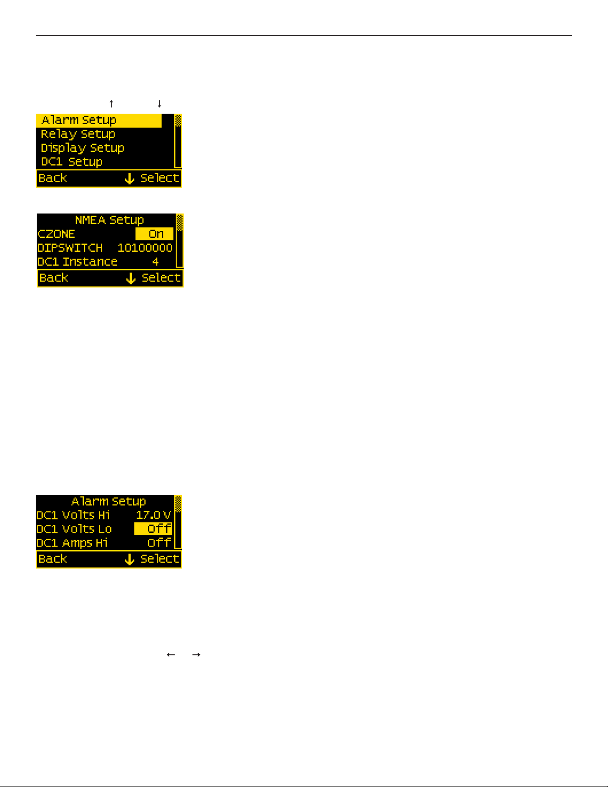
triggeredifachannelisaboveorbelowacertainuserselectedthresholdvalue.ThefollowingexampleindicateshowtosetupanovervoltageAlarm.
1.GototheAlarmSetupmenu.
2.Scrolltothedesiredinputchannel(i.e,DC1VoltsHi).
3.Press the Selectbuttonandthecursorshouldstartblinking.
4.Set the voltage threshold using the and buttons.(Holdingdownthebuttonsallowsfasterselection.)
5.Press the EnterbuttontosavethechangeortheCancelbuttontocancelanychange.
NOTE:Alowvoltagethresholdcannotbesetaboveahighvoltagethreshold.Likewise,ahighvoltagethresholdcannotbesetbelowthelowvoltage
threshold. The meter will automatically increase or decrease the voltage thresholds to enforce this.
Intheaboveexample,analarmwillsoundanytimeDC1voltageisgreaterthanorequalto17V.
Conguration
Setup Menu
MetersettingscanbeconguredfromtheSetupmenu.ThismenucanbeaccessedbypressingtheMenubuttonandthenscrollingtoandselecting
Setup. Press the UP and DOWN arrowbuttonstomovethecursor.Thedifferentsetupoptionsaredescribedbelow.
NMEA Setup
CZone Conguration
TouseCZone,rstconguretheDIPSWITCHsettingtomatchthesettingthatwasdenedintheCZonecongurationtool.ThenturntheCZonemenu
to ON.Themeterwillrebootandpullthecongurationinformationfromthenetwork.NotethattheNMEAcablemustbeconnectedtoaliveCZone
networkwithpropercongurationdata.TheCZonecongurationlewillautomaticallypopulatemostcongurationdatafortheM2VSMincluding:
NMEA2000instances,batteryvoltage,batterytype,batterycapacity,fullchargevolts,fullchargeamps,andtank/bilgeconguration.
NMEA 2000 Conguration
Fornon-CZonesystems,theuserwillhavetoenterNMEA2000instanceinformationforDC1,DC2,AC1,andtheTanks(ifused).
TheusershouldconguretheinstanceinformationbeforeconnectingtotheN2Knetworktopreventconicts.

9
Silent Alarm
Thisturnsoffthealarmbuzzer.Alarmswillonlyshowonthemainscreen.
Voltage Alarm
Voltagealarmscanbesettodetecthigh(Hi)orlow(Lo)voltageconditions.
Current Alarm
Thecurrentalarmcanbesettodetectovercurrentconditions.
State-of-Charge (SoC) Alarm
TheState-of-ChargealarmcanbesettodetectlowState-of-Chargeconditions.
Tank Alarm
Alarmscanbesettodetecttanklevels.
Bilge Alarm
Bilgealarmscanbesettodetectiftherun-timeexceedsacertainvalueinat60-minuteperiod(BilgeTimeHi)orifthenumberofcyclesina24-hour
period exceedsathreshold(BilgeCycleHi).
Alarm Delay
Analarmdelaycanbespeciedsothatalarmsdon’timmediatelytrigger.Thiscanbeusefulwhenmonitoringastartingbattery,sothatthealarmdoesn’t
trigger every time an engine is started.
Theholdofftimeroperatesasacount-up/count-downtimer.Whentheinputexceedsthealarmvalue,thetimerwillstartcountingupuntilitreachesthe
delaytime.Whenitreachesthedelaytimer,analarmwillsound.Ifthealarmconditiongoesawaybeforethedelaytimerhasbeenmet,thetimerwill
countdownuntilthetimeriszeroagain.Forexample;iftheAlarmDelayissetfor5minutesandanalarmconditionisactivefor4minutestheninactive
for1minute,ifthealarmconditionisactiveagain,thealarmwillsoundin2minutes(5minutes-4minutes+1minute).Notethatthereisonlyonedelay
per channel.
Clearing Alarms
Whenanalarmoccurs,thebuzzerwillsound,theredALARM LED will light. The screen will display which alarm was triggered, the alarm set point and
thecurrentvalue.Pressinganybuttonsilencesthebuzzerandanotherbuttonpressreturnstothepreviousdisplay.
Untilthecauseofthealarmisresolved,theALARM LED will remain ON and the channel that triggered the alarm
(Voltage,Current,State-of-Charge,orFrequency)willblink.
Viewing Alarms Status
Foranyactivealarm,theparameterwillashifitisdisplayed.Toviewacompletelistofactivealarms,pressMenu>Setup>Alarm Setup.Anyactive
alarmwillash.Youmayhavetoscrollthroughthemenutoseeallofthealarms.

10
Display Setup
ThemeterdisplaysettingscanbeaccessedfromtheDisplaySetupmenu.Fromthesetupscreen,scrolltoDisplaySetupandpresstheSelectbutton.
Thedifferentdisplaysettingsaredescribedbelow.Tochangeasetting,pressEnter and press the LEFT or RIGHT arrowbuttonstoviewthe
availablesettingoptions.PressEnter to save the setting. Press Cancel to cancel a change.
NoneofthesesettingsaremodiedbyCZone.
Brightness
Thissettingisforadjustingthebrightnessofthedisplay.Thevalueisapercentagewhere0%isdimmestand100%isbrightest.
Sleep Timer
Followingacertainperiodofinactivity,themeterwillenterasleepmodeandwillturnoffthedisplay.Anybuttonmaybepressedtoexitthesleepmode
and restore the display. The Sleep Timersetsthenumberofminutesfrom0to600beforeenteringsleepmode.Thisfeaturewillbedisabledbychang-
ing the setting to OFF.
Dim Timer
Inadditiontosleepmode,themetercanalsodimitsdisplayafteraperiodofinactivity.Thedurationofdelayinminutesfrom0to600canbeadjusted
withthissetting.ThisfeaturewillbedisabledbychangingthesettingtoOFF.BycontinuouslypressingtheLEFT buttonthemetercanbeplacedin
AUTOdimmode.Inthismodethemeterwillautomaticallydimaftertwominuteswhentheambientlightislow(nightmode).Whenthelightincreases,
themeterwillreverttoitsnormalbrightness.
Units
Select either Imprl(imperial)orMtrc(metric).Thesearetheunitsusedtospecifythebatterytemperatureanduidvolume.
Demo Mode
With Demo Mode ON,themeterdisplaysfactoryprogrammedvaluesfortheBatteryVoltages,Current,andState-of-Charge.Changingthesettingto
OFFreturnsthemetertodisplayactualmeasuredvalues.Thismodeistypicallyusedforcommercialorpromotionalpurposes.Note:Alarmsettingswill
still respond to the actual settings and not the Demo settings. To enter Demo Mode, press Menu>Setup>Display Setup>Demo Mode. Press the LEFT
or RIGHT arrowbuttonstotoggleDemoModeON or OFF.
Changing System Labels
TheM2allowstheusertochangethelabelsthataredisplayedaboveeachchannel.Eachchannelcanhaveamaximumof16characters
howeverinthesummaryscreensonlytherst5charactersofthebilgeandtankaredisplayed.IfCZoneiscongured,thenthelabelswillbe
overwrittenbyCZone.
Changing Label Names
Tochangethenameofabattery,followtheinstructionsbelow:
1.Navigatetothesetupmenuforthedesiredbattery(suchasDC1Setup).Menu->Setup->DC1 Setup
2.Inthebatterysetupmenu,movethecursortobatterynametobechanged(indicatedbythe >> symbol)
3. Press Select to enter the name editing mode.
4.UsetheLEFT and RIGHT arrowbuttonstomovethecursoroverthecharacters.
5. When the cursor is over a character, press Entertoeditthatcharacter.Thecursorwillstartblinking.
6.UsetheUP and DOWN arrowbuttonstoselectanewcharacterandpressOk to set that character.
7.Oncealldesiredcharactershavebeenchanged,presstheCancel buttontoexitthenameeditingmode.

11
DC1 Setup
Themeterprovidessetupsettingsforeachbattery.Toaccessthesesettings,rstgototheSetupmenu.Scrolltothedesiredbatterylabelfollowedby
Setup(suchasDC1Setup),thenpressSelect. NOTE:Somesettingsmaynotbeavailableforallbatteries.
Thebatterysetupsettingsaredescribedbelow.Tomakeachange,scrolltosettingandpressEnter. Press the LEFT or RIGHT arrowbuttonsto
viewtheavailablesettingoptions.PressEnter to save the setting. Press Cancel to cancel a change.
Enable
Todisplaythebatteryanditsmeasurements,changethissettingtoON.IfenableisOFF,thebatteryalongwithitsmeasuredvalueswillnotbedisplayed.
However,anyassociatedalarmsettingsarestillactive.Tode-activatethealarm,disablethemintheAlarmSetupmenu.
Set State-of-Charge (SoC) to FULL
Whenthisoptionisselected,themeterwillconsiderthebattery’spresentState-of-ChargetobeFULL. To do this, scroll to Ok and press Select.
The screen will then return to the meter summary display.
Battery Voltage
Thissettingindicatesthenominalvoltageofthebattery.Theoptionsare12V,24V,36V,&48V.ThisisautomaticallysetbyCZone.
Bat. Type
Thissettingindicatesthebatterytype.Theavailableoptionsarelistedbelow:
•FLStd-StandardFloodedLeadAcidBatteries
•AGM-StandardAbsorbedGlassMat(AGM)Batteries
•TPPL-ThinPlatePureLeadAGMBatteries
•GEL-GelBatteries
•FLRsv-FloodedAcidReserve.PremiumFloodedLeadAcidBatteriessuchasRolls.
•FLLoM-FloodedLowMaintenance.SealedFloodedLeadAcidBatteries
•FFFL-FireyAGMBatteries
Bat. Capacity
Thissettingindicatesthecapacityofthebatteryinamp-hours.Theavailablerangeis0Ato5000A.ThisisautomaticallysetbyCZone.
Full Chrg Volts
Thissettingindicatesthevoltageatwhichthebatteryisconsideredtobefullycharged.Theavailablerangeis0.1Vto70.0V.Thisshouldbesettothe
absorptionvoltageofyourcharger.Ifyoudon’tknowtheabsorptionvoltage,youcanguretheabsorptionvoltageoutbyobservingtheoutputvoltage
ofthechargeronceitenterstheabsorptionphase.Ifyouhavemultiplechargingsources,setittothehigherabsorptionvoltage.Inextremelyhotorcold
temperaturestheabsorptionvoltagewillneedtobesetslightlyhigher(forcold)orslightlylower(forhot).ThisisautomaticallysetbyCZone.
Example 1.InBlueSeasSystems’P12ChargerthisparameteriscalledtheAbsorb Voltage. For lead acid values, the default value is 14.5 V DC. So in
the M2 the Full Chrg Voltssettingwouldbesetslightlysmallerthanthe14.5V(14.4V).
Example 2.Anunknown10Achargerisconnectedtoapartiallydischargedbattery.Initiallythemetershouldreadapproximately10Aofchargingcurrent
withthevoltageincreasingovertime.Atsomepoint(around14.5-14.8VDC)thevoltageshouldstabilizeandthechargingcurrentwillstartdecreasing.
This voltage is the Full Charge Voltage. Set the Full Chrg Volts to0.1Vbelowtheobservedvoltage.

12
Full Chrg Amps
InadditiontoVoltage,theusercansettheChargingCurrentatwhichthebatteryisconsideredfullycharged.Thevalueisapercentagebetween0.0%
and10.0%ofthebattery’ssetAmp-hourcapacity.Thisvalueshouldbesetto0.2%higherthantheEndofAbsorptionAmps.Thatisthecurrentwhere
thebatterychargerswitchesfromAbsorbtoFloatstage.Valuesaretypically2%forAGMand3%forLeadAcid.Asabatteryages,thispercentagemay
needtobeincreased.ThisisautomaticallysetbyCZone.
Charge Eff.
Thissettingisforindicatingthebattery’spercentchargeefciency.Thevaluemaybesetbetween0%and100%.Theusercanadjustthecharge
efciencyupordowndependingontheageand/ortypeofbatterythattheyareusing.AGMBatteriestendtobemuchmoreefcientthanLeadAcid
Batteries.IftheM2meterindicates100%beforethechargerisdonewithitsbulkchargethentheefciencyislikelytoohigh.Trydecreasingitacouple
percent.IftheM2meterneverindicatesfullchargethenefciencyislikelytoolow.Tryincreasingitacouplepercent.Thisisautomatically
setbyCZone.
Thechargeefciencycanbecalculatedasfollows:
1. Set the Charge Eff.Valueto100%.
2. Dischargethebatterysomewherebetween25%to50%.
3. Check the SoC summary screen and note the Ah Usedvalue(itwillbeanegativenumber).Thisis Discharge Amps.
4. Chargethebatteryusinga3-stagecharger.
5. WhenthechargergoesfromAbsorptiontoBulk,thebatteryisconsideredfullycharged.
6. Check the SoC screen again and note the Ah Used(itwillbeapositivenumber).ThisisCharge Amps.
7. ThenewChargeEfciencyvalueiscalculatedbyDischarge Amps/Charge Amps.
8. Set the Charge Eff.valuetothevalueabove
Forexample,ifwehada100Ahbattery,wewouldremove50AhatroughlyC/20(5Ampsfor10hours).Wewouldthenchargethebatteryandwhenwe
transitiontooat,wemightsee4Ah Used.Sothechargeefciencywouldbe50/(50+4)or92.5%efciency.
Temperature
Specifythelowesttemperaturethatthebatterieswillbeexposedto.Astemperaturedrops,theeffectivecapacityofbatteriesalsodrops.
TheM2calculatesthebatterycapacitybasedonthisworstcasetemperature.Thisnumbercouldbeadjustedseasonallytoprovidebetteraccuracy
SoC Volt. Sync
ThissettingallowtheM2toestimatethecurrentState-of-Chargeafterthebatteryhasrestedforaperiodoftime.Incertainsituationswheresmall
chargesareaffectingthevoltagereading(somesolarinstallationswoulddothis),thesynchronizationwillestimatetheSOCincorrectly.Inthatcase,turn
this feature off.
Shunt Value
TheM2isshippedwithasingle500A/50mVshunt(theratiois10000:1).Theshuntvalueassumesthatthefullscaleshuntoutputvoltageis50mV.To
useashuntwithasmalleroutputvoltageusethefollowingformula:ShuntValue=(NewShuntRatio)/20.Forexampletousea400A/20mVshunt
(Note:20mV=0.02V),youwouldsetShuntValueto(400A/0.02)/20=1000A.
Zero Shunt
Menu->Setup->DC1 Setup->Zero Shunt.Tozeroouttheshunt,connectbothofthecurrentsensewirestothenegativebusbarsideoftheshunt.
Then press the ResetbuttonontheM2Metertoconrmtheaction.
State-of-Charge (SoC) Cycles
Menu->Setup->DC1 Setup->SoC Cycles.TheSoCCyclesoptionallowstheusertoresetthebattery’srecordedSoCcyclesto0.Todothis,scrollto
and press Select onSoCCycles.Textwillappearaskingtoconrmorcanceltheresetrequest.PressYestoconrmorNo to cancel the action.
State-of-Charge (SoC) Default Settings
Toresetthebattery’sState-of-Chargesettingstothedefaultvalues,pressSelectonSoCDefaults.Textwillthenappearaskingtoconrmorcancelthe
resetrequest.PressYestoconrmor Notocancel.Thefollowingchangeswilloccurafterareset:
1.SoCCycleswillberesetto0
2.SoCisResetto98%

13
DC2 Setup
Enable
Turnthechannelonoroff.IfEnableissettoOFFthenthechannelwillnotbedisplayedinthemainmenus.Thealarmfunctionsforthatchannelwill
notbedisabled.Todisablethealarmforachannel,setthealarmforeachchannelto OFF.
AC1 Setup
Enable
To display the channel and its measurements, change this setting to ON.IfenableisOFF,thechannelalongwithitsmeasuredvalueswillnotbe
displayed.However,anyassociatedalarmsettingsarestillactive.Tode-activatethealarm,disablethemintheAlarmSetupmenu.
Toggle A/V
SwitchtheCurrentandVoltagedisplayonthechannel’sSummaryScreen.IfthisoptionissettoOFFthenVoltagewillbedisplayedinthecentereld.
If the option is set to ON Currentwillbedisplayedinthecentereld.
Example:ToggleA/VSettoOFF
Full Scale Amps
TheM2isshippedwitha150AAC/50mAACcurrenttransformer(theratiois3000:1).Thefullscaleoutputisbasedontransformerswithamaximum
outputvalueof50mAAC.Adifferentvaluetransformercanbecalculatedwiththefollowingformula:FullScaleAmps=NewRatio/20.Forexampleto
replacethestandardtransformerwitha100A/20mAtransformer(Note:20mA=0.02A):(100A/0.02)/20=250A.
Tank / Bilge Setup
Themeterhastwoinputsthatcanbeconguredaseitherabilgeortank.Toaccessthesesettings,rstgototheSetupmenu.
Scrolltothedesiredinput.Thetanksetupsettingsaredescribedbelow.
To make a change, scroll to setting and press Enter. Press the LEFT or RIGHT buttonstoviewtheavailablesettingoptions.
Press Enter to save the setting. Press Cancel to cancel a change.
Select
Denewhatisconnectedtotheinput:Bilge, Tank, or Off.IfCZoneisenabled,thenCZonewillcongurethiseld.IfselectisOFF, the input along with
itsmeasuredvalueswillnotbedisplayed.However,anyassociatedalarmsettingsarestillactive.Tode-activatethealarm,disablethemintheAlarm
Setup menus.
Bilge Functions
Cycle Reset
Resetthebilgecyclecountertozero.
Tank Functions
Volume
Setthevolume.CZonewillautomaticallycongurethissetting.
Show Percent
If this value is ON, then tank values will displayed as a percentage. If the value is OFFthenitwillbedisplayedineithergallonsorliters.
Sensor Type
ThissettingpresetstheResistanceLoandResistanceHivaluesbasedonthetypeofsenderattachedtothemeter.TheCZonecongurationtoolwill
setthisautomatically.Theavailableoptionsarelistedbelow:
• USA–NorthAmericanStandardtypeofsenderbetweenwitharesistancebetween240and33ohms.
• Euro–EuropeanStandardtypeofsenderwitharesistancebetween10and180ohms
• 1810–BlueSeaSystemsUltrasonicTankSenderforDiesel,Water&Waste.
• 1811–BlueSeaSystemsUltrasonicTankSenderforGasolineOnly
• Cstm–IndicatestheResistanceLoorResistanceHivaluehasbeenmanuallychanged.

14
Resistance Lo/Resistance Hi
Thetankmeteroperatesbyreadingtheresistanceofthetanksender.Theresistancevalue(inohms)canbeenteredhereforanemptytank
(ResistanceLo)andforafulltank(ResistanceHi).ChangingeitherofthesevalueswhentheSender Type is set to either 1810 or 1811 will give
unpredictableresultswhenanUltrasonicTankSenderisused.
Tank Depth (Only used with 1810 and 1811 Senders)
Thissettingindicatesthedepthofthetankininches.ThissettingisnotaffectedbyswitchingtheunitsinSetup->Display->Units.Alsonotethatthis
setting is only used for ultrasonic senders.
Tank Shape
• Rect – Standard Rectangular Tank
• Tri–TriangularShapedTank.GoodfortanksinBilges.
• Auto–Thissettingonlyshowsupafterthetankhasbeenautocalibrated.ChangingthisvaluebacktoRectorTriwilloverwritetheauto-calvalues.
• Cstm–ThissettingindicatesthattheUserhasmanuallychangedthetanksettings.
Custom Tank Shapes
TheM2TankMetercandenecustomtankshapes.ThiscanbedonetwowaysbyeitherusingtheAutoCalibratefeatureormanuallyenteringthetank
Parameters.ForCZonesystems,customshapesaredenedinthecongurationtool.
Manually Entering Custom Tank Shapes
TheM2TankMeterhasvesetuppointsthatcanhelpdeneoddsizedshapes.Eachofthesetpointsallowstheactualvolumeofthetanktobedened
forvarioussensorreadings.Forexample,settingtheSensor20%valueto10%,indicatesthatwhenthetanksensorreads20%thetankisreallyjust
10%full.Similarsetpointsareavailableat40%,60%,80%,and100%.
Ifatankcanbecompletelyemptied,thentocalculatethesetpointsdothefollowing:
1. Emptythetank.(Ifthetankcannotbecompletelyemptied,theestimationworksbestifthetankisemptiedwiththesensorreadingunder20%.)
2. SetthetanksshapetoRect.(Rectangular)
3. Set the tank to display percentage.
4. Addliquidtothetankuntilthemeterreads20%.
5. Recordtheactualnumberofgallonsaddedtothetank.
6. Keeponaddingliquidandrecordthenumberofgallonsaddedwhenthemeterreads40%,60%,80%and100%.
7. Press Setup->Tank X Setup and scroll down to Sensor 20%.
8. Enterthefollowingvalue:(TankCapacity–TotalGallonsAdded+GallonsAddedat20%)/(TankCapacity)
9. RepeatStep8for40%,60%,80%and100%.
Example: Triangle Tank
Auserhasatrianglefueltankthathasatank
capacityof50gallons.Thetankisn’tcompletelyempty
andthemeterreadingislessthan20%inRectangular
mode.Theuseraddsfueluntilthemeterreads20%.
Theamountoffueladdedwas1gallon,at40%hehas
added7gallons,at60%hehasadded17gallons,at
80%hehasadded31gallonsandat100%hehasadd-
ed 49 gallons. The total gallons added is 49 gallons.
TocalculatetheSensor20%valueweusethe
equationinstep8above:(50g–49g+1g)/50g=4%.
TocalculatetheSensor40%valueweusethe
equationinstep8above:(50g–49g+7g)/50g=16%.
Likewisewecancalculatetherestofthevalues
(60%&80%)asshowninthetable.
100%-Sensor80%
fullValue%-80%
100%-75%
90%-80%
Sensor 100%=Sensor 80%+20%*
=75%+20%*
=125%
Note:Itispossibletohavethetankfullbeforethesensorreads100%byinputtingavalueintotheSensor100%eldthatisgreaterthan100%.For
exampleifthesensorreadingforafulltankis90%andSensor80%iscalculatedtobe75%thenSensor100%canbecalculatedwiththefollowing:
Rectangular
Tank
Reading
100%
Gallons
Added
at X%
49 gallons
Sensor
X%
100%
Custom
Tank
Reading
50 gallons
80% 31 gallons 64% 32 gallons
60% 17 gallons 36% 18 gallons
40% 7 gallons 16% 8 gallons
20% 1 gallon 4% 2 gallons
0% 0 gallons -0 gallons

15
Using Auto-Calibrate
TheAuto-Calibratefunctionrequiresthetanktobelledataconstantrateandforthesensorreadingbeinitiallylessthan15%.Forgrey,waste,and
watertanksahosecanbeusedtoprovideaconstantow.Dieselandgastankscanbemoredifcultbecausefoamingmaycausetheusertoslowdown
llingoncethetankisalmostfull.Iffoamingisaproblemthenusethemanualmethoddescribedabove.
1. Select Setup->Tank(1-4)->Auto Calibrate->Ok
2. Ifthesensorreadsmorethan15%anerrormessagewillbedisplayedalongwiththesensorreading.Atthispointthetankcanbeemptiedor
thebackbuttoncanbepressedtoexittheautocalibrateprocedure.
3. Ifthesensorislessthan15%thenanoptiontostartthecalibrationprocessisgiven.
4. Press the Startbuttonandstartllingthetankataconstantrate.
5. Thetimerwillstartcountingasthetanklls.Inadditionthesenderwillindicatethatthetankisgettinglled.Whenthetankreaches100%
the timer will automatically stop. Press the FinishbuttontoacceptthecalibrationvaluesortheCanceltoabandonthechanges.Ifthetankis
fullbeforethesenderreaches100%thenpressFinish.
6. AftertheFinishbuttonispressedtheM2willpopulateSensor20%-Sensor100%withthepropercalibrationvalues.Scrolldowntoinspect
the values.
Version Info
TheVersionInfooptionintheSetupmenudisplaystheproductname,serialnumber,andsoftwareversion.Thisinformationwillbedisplayedonascreen
after scrolling to Version Info and pressing Select.PressinganybuttonwillreturntotheSetupmenu.
Factory Reset
TheFactoryResetoptionintheSetupmenuallowstheusertorestorethemeter’sfactorydefaultsettings.FirstscrolltoFactoryResetand
press Select.Textwillappearaskingtoconrmorcanceltheresetrequest.PressYes toconrmorNo to cancel the reset.

PGN’s Used with 1850
PGN Number Description Fields
127506 DC Detailed Status State-of-Charge(Timeremainingwillfollow)
127508 BatteryStatus BatteryVoltage,BatteryCurrent
127503 ACInputStatus Voltage, Current, Real Power
127504 ACOutputStatus Voltage, Current, Real Power
127505 FuidLevel Type,Level,Capacity
PGN Number Description
59392 ISOAcknowledgement
59904 ISORequest
160160 ISO Transport Protocol, Data Transfer
60416 ISO Transport Protocol, Connection Management
60928 ISOAddressClaim
65240 ISOCommandedAddress
126208 RequestGroupFunction
126993 Heartbeat
CZone Proprietary PGN’s
65280 PGN_ZONE_COMMAND_MESSAGE Circuits
65281 PGN_ZONE_FEEDBACK_MESSAGE FeedbackonCircuits
65284 PGN_CZONE_STATUS_MESSAGE Connectionanddeviceinfo(serial/rmware/..)
65288 PGN_ZONE_COMMAND_MESSAGE
65290 PGN_CONFIG_CLAIM Conglerequest
65291 PGN_DATA_BLOCK_FEEDBACK Congle
65293 PGN_SI_RAW_DATA_REQUEST_MESSAGE Not used for MV
65295 PGN_CZ_ALARM_MESSAGE AlarmPGN
65297 PGN_CZONE_ENGINEERING_MSG Congtoolcommunication
130816 PGN_DATA_BLOCK ForCong.Transfer
16

Software Upgrade
New Method
1. ThisupgrademethodonlyworkswithWindows7PCsandabove,andMACOSX10.8andabove.
2. Downloadthenewrmwarefromhttp://www.bluesea.com/m2rmware.
3. Extractthermware.binlefromziple.
4. Remove all connections from the meter.
5. PlugaUSBmicrocableintothebackofthemeter.
6. Whileholdingthe2ndbuttonfromtheleftconnecttheUSBcabletoaPCoraMAC
b.OnaMAC...
7. Thecomputerwillcreateanewdriveonthecomputer.Note:IfthePCdoesn’trecognizetheM2-VSM,thentryusingadifferentcable.
a.OnaPC,thenewdrivewillhavebelabeledasCRP_DISABLD(D:)where“D:”isthedriveletterandmaybeadifferentletter.
While holding the 2nd button from the left connect the USB cable to a PC or a MAC
17

18
9. Copythenewrmware.binletotheM2-VSMfolder.
10.UnplugtheUSBcablefromthecomputer.
11. Youcanplugtheusbcablebackintothecomputertoverifythenewrmware.TheM2-VSMshouldpower
up and you can navigate to Setup->Version Info to verify the new SW Revision.
4600 Ryzex Way
Bellingham,WA98226USA
p 360.738.8230
f 360.734.4195
bluesea.com
980033760 Rev. 001
8. Deletethermware.binlefromtheM2-VSMfolder.
a.OnaPC,selectthelewithyourmouseandpressthedeletekey.
b.OnaMac,selectthelewithyourmouseandmovetotrash.
Table of contents
Other Blue Sea Systems Measuring Instrument manuals


