Blue Sky Energy - Solar Boost 3024(D)iL
1Blue Sky Energy | USA | www.blueskyenergyinc.com
TABLE OF CONTENTS
IMPORTANT SAFETY INSTRUCTIONS .................................................................................................................. 2
PRODUCT DESCRIPTION...................................................................................................................................... 3
Part Numbers and Options .................................................................................................................. 3
OPERATION ........................................................................................................................................................ 3
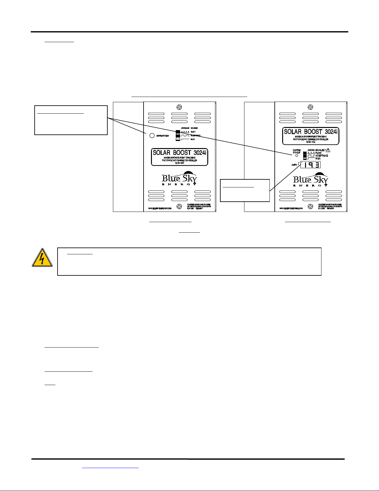
Charge Status Indicator........................................................................................................................ 4
Optional Digital Display........................................................................................................................ 3
Optional Remote Displays.................................................................................................................... 3
Multi-Stage Charge Control ................................................................................................................. 3
Bulk Charge .................................................................................................................... 3
Absorption (Acceptance) Charge ................................................................................... 3
Float Charge................................................................................................................... ..4
Equalization ......................................................................................................................................... 4
Automatic Equalization.................................................................................................. 4
Manual Equalization ...................................................................................................... 4
Current Limit........................................................................................................................................ 4
Temperature and Output Power ......................................................................................................... 4
Optional Temperature Compensation................................................................................................. 5
Maximum Setpoint Voltage Limit ........................................................................................................ 5
Maximum Power Point Tracking (MPPT) ............................................................................................. 5
Multiple Charge Controllers On The IPN Network ............................................................................... 5
INSTALLATION..................................................................................................................................................... 5
Electrostatic Handling Precautions ...................................................................................................... 5
Selecting PV Modules .......................................................................................................................... 6
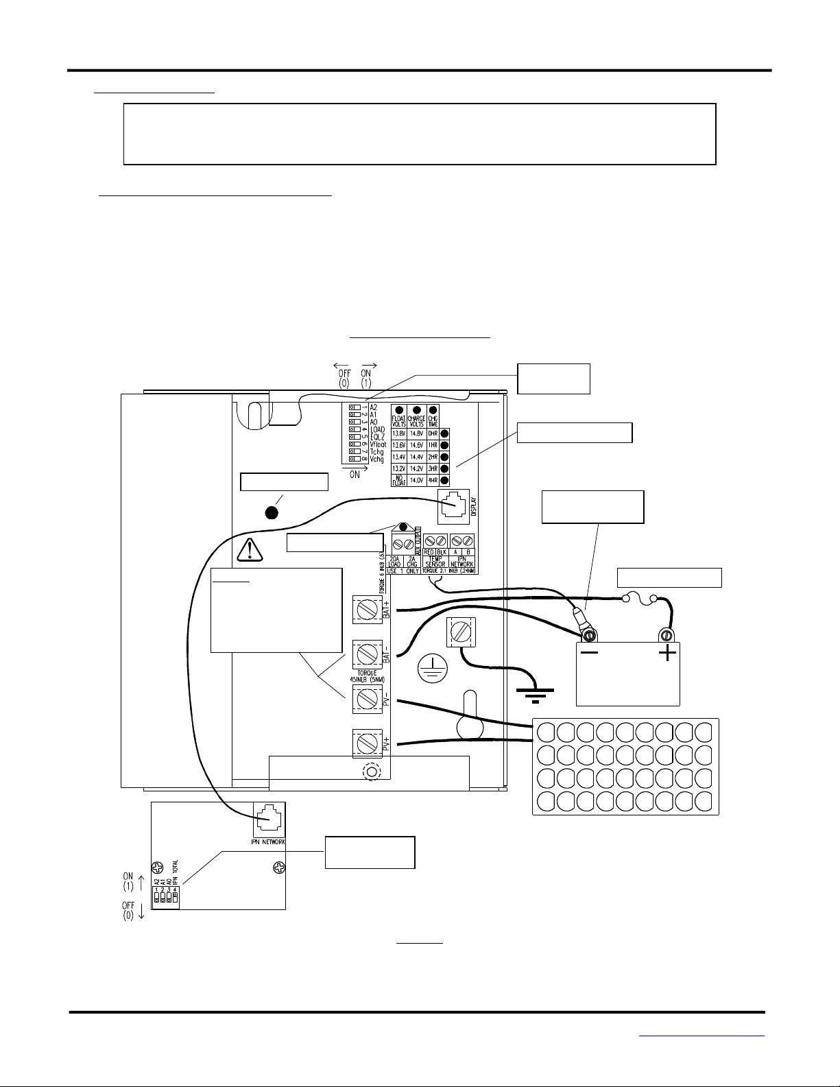
Solar Boost 3024i Setup....................................................................................................................... 6
As Shipped Factory Default Settings............................................................................... 6
Restoring As Shipped Default Settings ........................................................................... 6
Battery And PV Voltage.................................................................................................. 7
Charge Voltage, Float Voltage & Charge Time ............................................................... 7
Output Current Display .................................................................................................. 8
Battery and PV Wiring ......................................................................................................................... 8
Electromagnetic Compatibility............................................................................................................. 8
Battery Temperature Sensor ............................................................................................................... 8
Auxiliary Output................................................................................................................................... 8
Auxiliary Battery Charge................................................................................................. 9
Load Controller .............................................................................................................. 9
Dusk-to-Dawn Lighting Control...................................................................................... 9
Installing a Multi-Controller System .................................................................................................... 10
Multi-Controller Wiring And Setup ................................................................................ 10
IPN Network................................................................................................................... 10
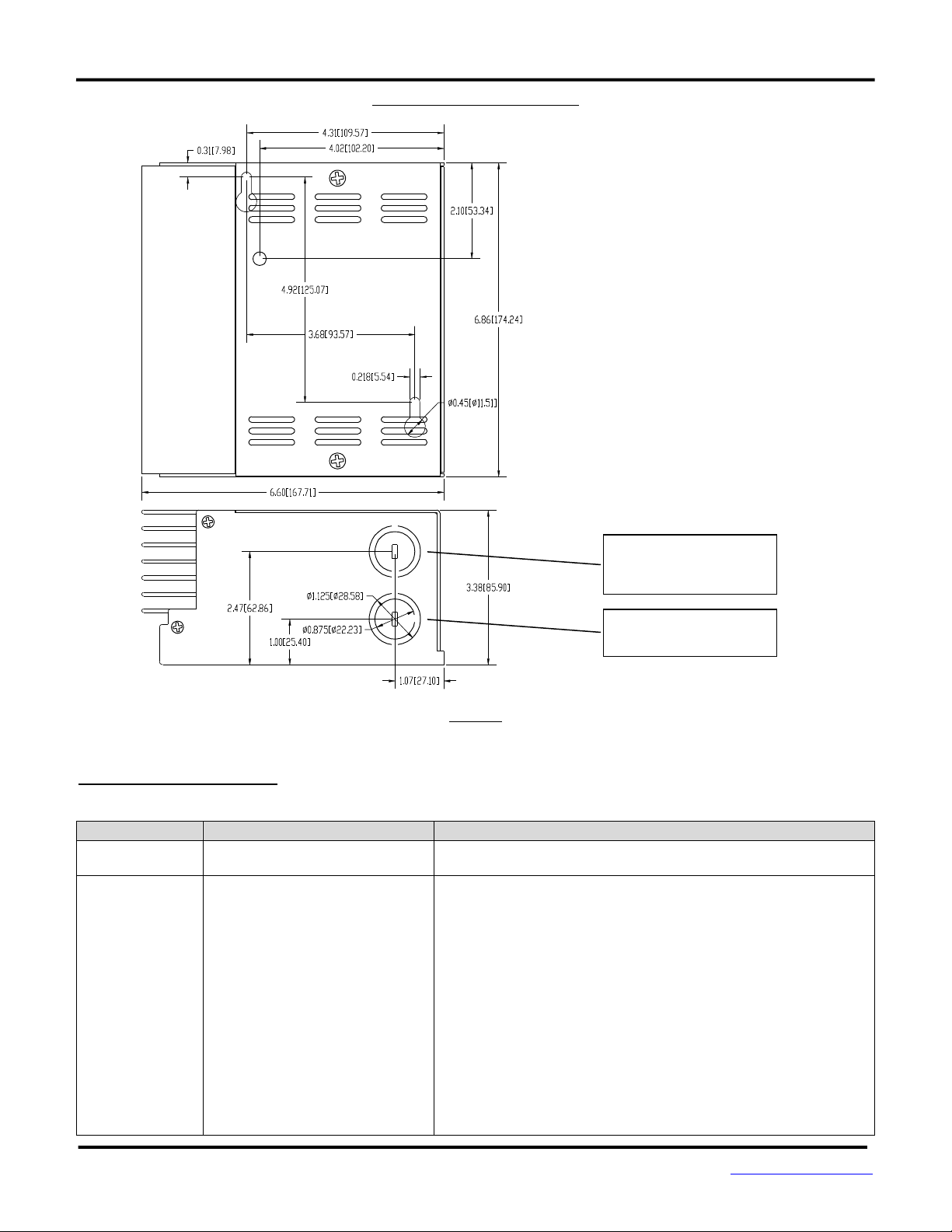
Mounting ............................................................................................................................................. 11
TROUBLESHOOTING GUIDE ................................................................................................................................ 12
SPECIFICATIONS .................................................................................................................................................. 14
TWO YEAR LIMITED WARRANTY ........................................................................................................................ 15
TABLES AND FIGURES
Table 1 Charge Status Indicator.................................................................................................. 3
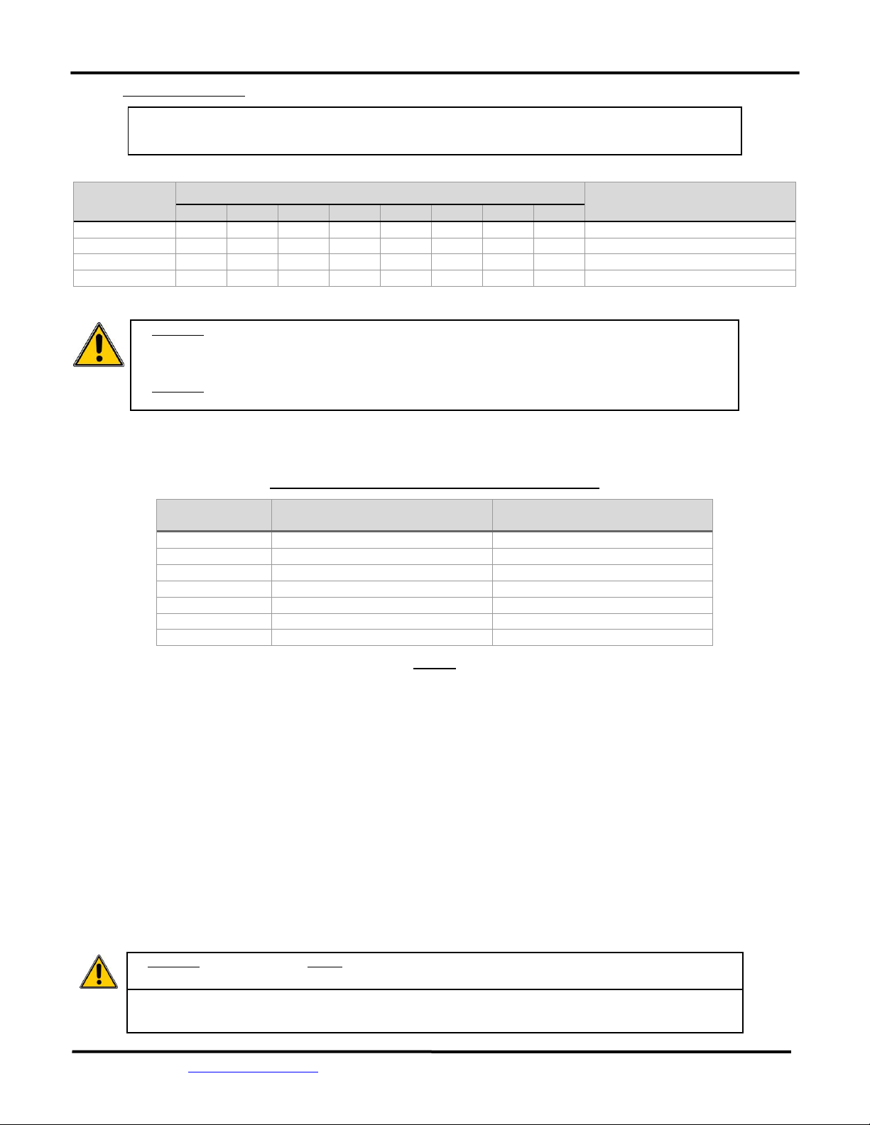
Table 2 Maximum Conductor Length - 3% Voltage Drop............................................................ 8
Figure 1 Front Panel and Remote Display Indicators ................................................................... 4
Figure 2 Factory Charge Voltage Setpoint -vs.- Battery Temperature ......................................... 5
Figure 3 Setup and Wiring Diagram ............................................................................................. 7
Figure 4 Auxiliary Output Wiring.................................................................................................. 9
Figure 5 IPN Network Wiring ....................................................................................................... 10
Figure 6 Detailed Dimensional Drawing....................................................................................... 11