Blue Square Labs Q360 Product manual

Page | 1
V14612INSLM
V
Va
al
lv
ve
e
I
In
ns
st
ta
al
ll
la
at
ti
io
on
n
a
an
nd
d
M
Ma
ai
in
nt
te
en
na
an
nc
ce
e
G
Gu
ui
id
de
e

Page | 2
V14612INSLM
IMPORTANT SAFETY INFORMATION
When installing and using this equipment, basic safety precautions should always be
followed.
**READ AND FOLLOW ALL INSTRUCTIONS**
WARNING: To reduce risk of injury, do not permit children to use this product unless they
are closely supervised at all times.
Swimming Pool equipment can generate high pressures capable of causing injury.
Always use caution when manipulating valves associated with the pool equipment and
turn off the pump if pressures exceed manufacturer’s specification. Always turn off the
pool equipment when disassembling or servicing your circulation system.
Swimming Pool equipment can create suction sufficient to entrap even adults. If pool
fittings are broken or missing, turn off your equipment and contact a certified swimming
pool expert to make the needed repairs.
To ensure proper cleaning and to qualify the warranty, fax or email a System Design Form
provided by Blue Square along with a scaled pool plan for a FREE certified In-Floor
Design. (New pool construction only.)
Email: plans@bluesquaremfg.com
Fax: (888) 282-6955
If the pool plan design or dimensions change during excavation, a revised plan must be
submitted to Blue Square in order to maintain warranties.
Install the valve above ground at finished pool water level. Do not bury top of clear lid
and inlet of valve after installation.
Install cleaning heads and nozzles according to the Design Plan.
If pool includes an elevated spa, install a check valve on the line feeding the spa heads
to avoid spa draining. Install other check valves (as normal) to avoid spa return jets and
suction lines from draining. For multiple elevation changes in bodies of water and/or
negative edge water features, please contact our design center. (800) 277-4150.
SAVE THESE INSTRUCTIONS
For customer service or support:
For on-line support: www.bluesquaremfg.com
To contact Blue Square: Customer Service
525 E Baseline Road
Suite 107
Gilbert, AZ 85233
(800) 277-4150
Page | 3
V14612INSLM
INTRODUCTION
The Q360 In-Floor Cleaning system is designed to give years of service. The benefits of
deep circulation are well documented and scientifically proven to give the most
efficient swimming pool circulation available. This superior circulation delivers substantial
chemical, electrical and heat savings to the pool owner while offering outstanding
cleaning benefits as well.
The unique engineering of the Q360 System smoothly transfers power from the turbine to
the ports or outlets with minimal friction loss and back pressure, allowing the maximum
possible flow rate to the in-floor cleaning jets. The open gear design allows for effective
pass-through of debris, greatly minimizing annoying cleaning system disruptions and
lowering maintenance costs even further over other in-floor systems.
The Innovative pressure-safe valve design protects your system by ensuring that one port
is always open. Large 2" inlet and (6) 2" ports maximize flow rate. Reinforced space-age
molded construction weathers the elements and is saltwater/chemical friendly. See-
through lid design allows for inspection of turbine and gears without the need for
disassembly.
Failure to follow recommended installation methods could void warranties and cause
injury.
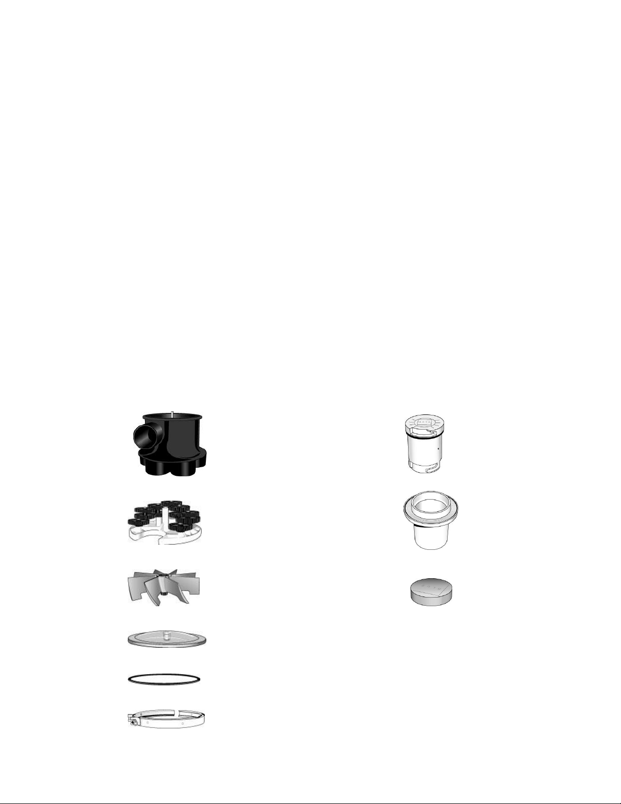
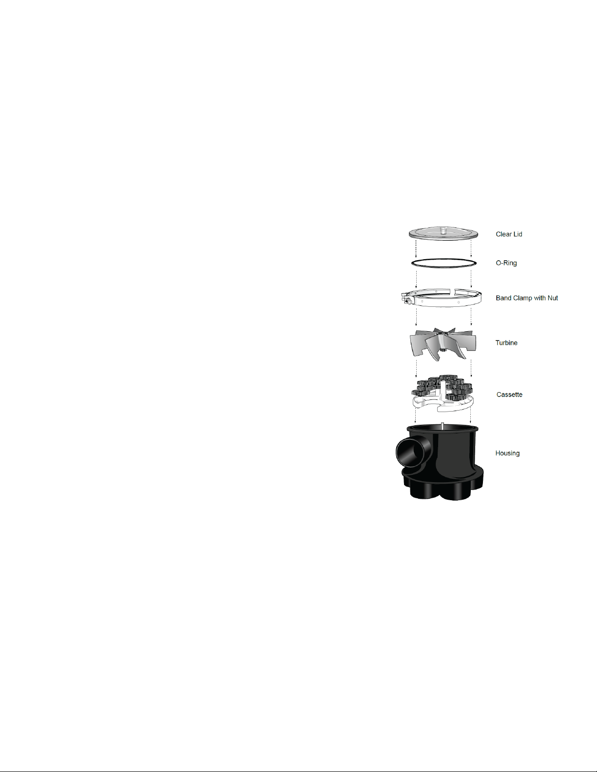
COMPONENTS
The Q360 High Performance Water Valve: The Q360 Jet Complete:
A. Valve Housing or Body A. Jet (High Flow & Low Flow)
A. Cassette B. Collar
B. Turbine C. Protective Cap
B. Clear Lid
C. O-Ring
D. Band Clamp w/ nut

Page | 4
V14612INSLM
INSTALLATION
1. Site Planning
Verify that the excavated pool matches the Blue Square Certified Pool Plan.
Check the break, width, depth and designated step/bench locations. Blue
Square design dimensions are from finished pool edge. They are not taken from
the excavation edge. Allowances will need to be made for the thickness of the
shell according to your pool companies specifications and local codes. If any
aspects of the pool design change during the construction process, please
resubmit an updated plan with the changes for a new Factory Authorized Plan to
ensure proper cleaning and circulation. Failure to follow the FREE factory
authorized design and to ensure that the pool is built to the plan specifications
may void the warranty.
In order to save on plumbing costs, position the valve as close as possible to the
swimming pool or water feature. The valve should be at least five feet away from
the water’s edge. (Check the bonding codes in your area.) The low profile
design, the quiet and smooth operation of the Q360 Water Valve allows for the
valve to be inconspicuously hidden by an irrigation box or landscaping.
Although servicing the valve is very rare, the valve should be placed in a location
where it may be easily accessible.
Install the valve so that the lid and band clamp are above grade and the top of
the valve housing is 2-3” above the water level of the main body of water. If a
below water level installation is necessary, serviceable check valves or manual
valves on all of the inlet and outlet ports will be required to prevent flooding when
servicing the valve.
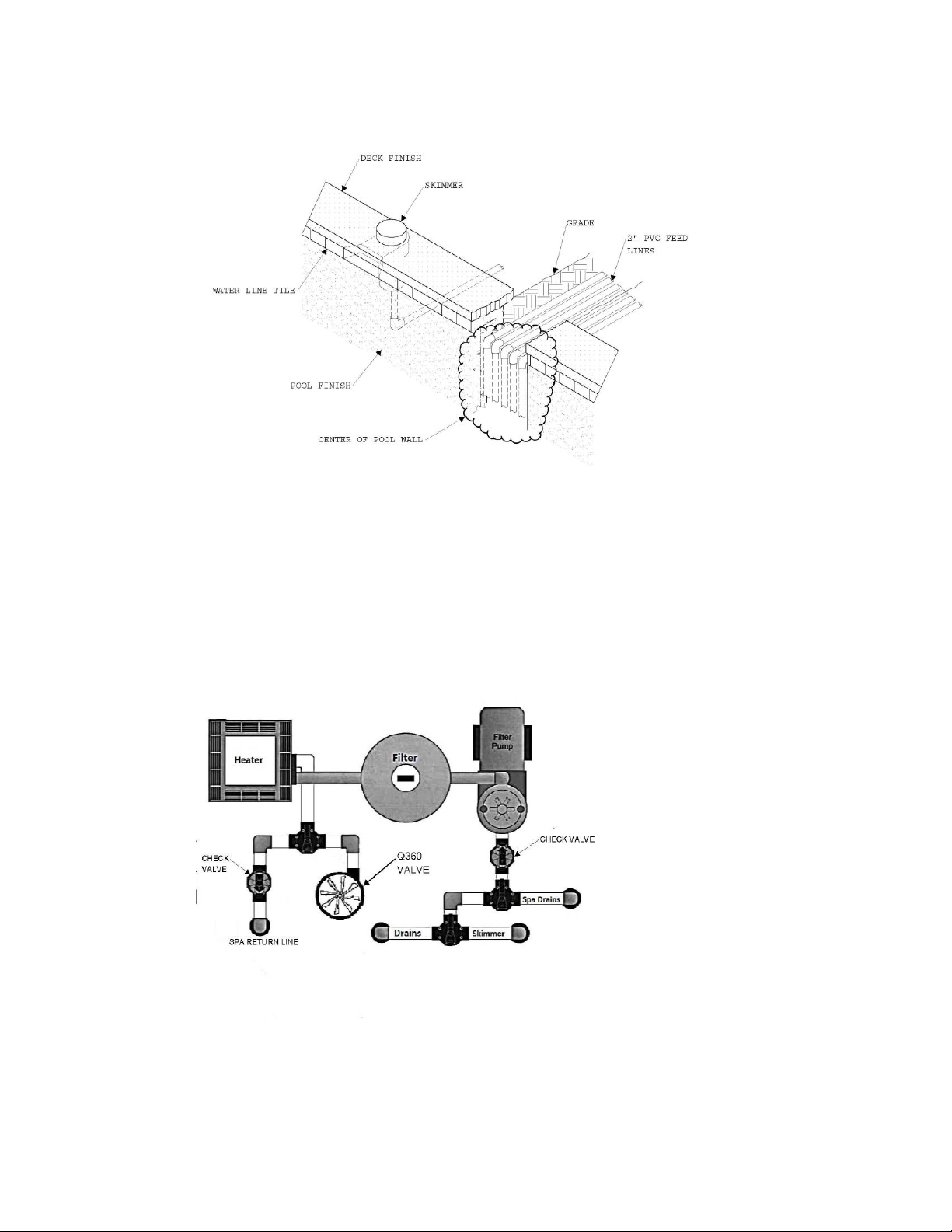
In order to reduce plumbing costs; layout the system so the feed pipes enter the
pool close to the center of the pool nearest the pool equipment. See Fig. A 1-1
& Fig. A -1-2
Fig. A 1-1
Page | 5
V14612INSLM
Fig. A 1-2
Just like any other plumbing, a check valve is needed on the feed line running to
an elevated spa or a different elevation body of water to prevent drain-back or
equalization. See Fig. A 1-3
Fig A 1-3
Follow the design plan to position and stake the cleaning head locations. Each
head has a designated nozzle that has a precise cleaning radius. Perimeter
heads have a one foot overlap. Mark the cleaning radius around each stake

Page | 6
V14612INSLM
with a 5’ arch to verify cleaning coverage. Keep in mind that the jets clean
much further. The design allows for overlap to prevent debris accumulation in-
between filter cleaning cycles.
2. Plumbing the System
The Blue Square certified plan indicates which cleaning heads will be plumbed
together to form a bank. Run all feed lines to the top of the bond beam to
facilitate easy valve hookup. Number the lines
according to the design plan. Keep in mind that
the valve cycles counter clockwise from the top
view.
Excavate niche in pool wall, 6 x 24” down to
the pool floor
Make line trench depth sufficient to cover all
pipes
Do not cross lines in floor
Use 2” Schedule 40 pipe
Position so jet feed lines are perpendicular to
the slope of the finished pool floor.
See Fig. A 1-4
Fig. A 1-4
Cleaning Head Risers / Stub-ups
The cleaning head collars require a 2” Schedule 40 riser with no reaming required.
*These stub-ups should be perpendicular to the slope of the pool floor.
Plumbing the Valve (see Plumbing the System Diagram)
Remove the Cassette / Gears during pressure testing to allow for equal
distribution of pressure down all 6 ports or zones. Store the Cassette with the jets
for reinstallation at start-up. Position the O-ring on the valve housing in the O-ring
groove. Align the center hole on the clear lid with the guide pin in the lid and use
the band clamp to secure the clear lid to the valve housing. If the lid does not sit
firmly on the O-ring the cassette is not in the full down position. Replace (re-drop)
the cassette into the vavle to make sure the outer gears engage with the gear
train on the interior perimeter of the valve housing.
When plumbing the valve housing use heavy bodied PVC glue with a compatible
primer. It is best to prime the housing heavily to ensure a good glue joint.
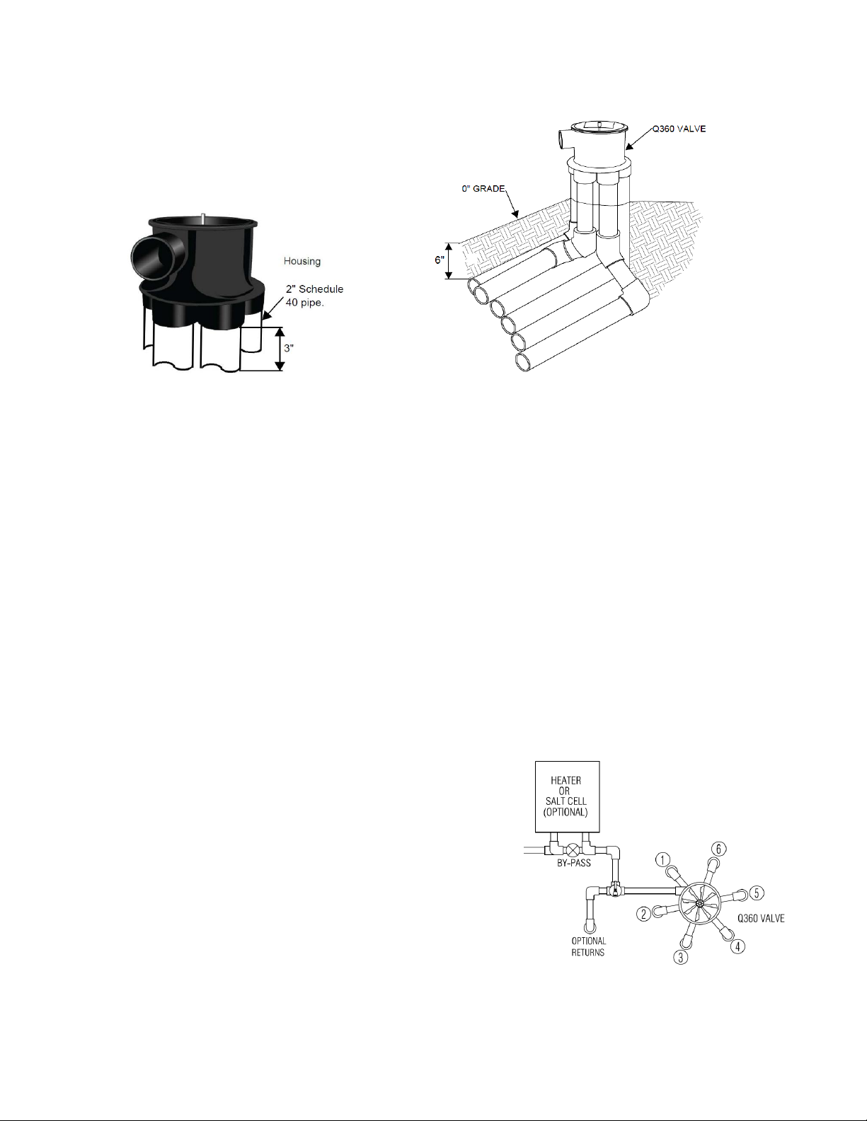
Discharge or Feed Lines
The Q360 valve uses 2” Schedule 40 pipe. Use a 3” stagger when cutting pipes
to provide enough clearance. See detail. See Fig. A 1-5
Page | 7
V14612INSLM
Fig. A 1-5 Fig. A 1-6
Install the discharge lines from the valve in a stacked or flat configuration.
See Fig. A 1-6
Use heavy bodied PVC glue to connect PVC fittings to the valve housing. Do
not get glue inside the housing as it will void the warranty.
Install lines a minimum of 6” below grade or in accordance with local codes.
The distribution system is usually designed to rotate from shallow to deep,
following your factory design. Looking down on the valve, it rotates counter-
clockwise. If a spa is included in the application, it will require a dedicated
line from the valve and a check valve if it is a raised spa.
If all outlet ports on the valve are not needed, use the Y-Pipe as noted in the
plan to aid in efficiency and reduce plumbing costs. *Note: Surface returns
can be applied to the unused port.
Never tie a raised spa bank with any plumbing from a lower body of water
and drain down.
Consult the design plan for proper connections.
Auxiliary Equipment
Heaters
To compensate for heater system pressure
drops, plumb heaters in a bypass line before the
water valve. The heater bypass valve should be
adjusted to ¾ open. See Fig. A 1-7
Chlorinators
In-floor systems can be used with erosion
feeders, ozone generators and in-line salt
converters. Consult manufactures instructions
for proper installation to protect water valve
and other pool equipment. Any chlorinator with
a venturi or restrictive channels should be
plumed with a bypass. See Fig. A 1-7 Fig. A 1-7
Page | 8
V14612INSLM
Pressure Testing
Pressure-test the system at a minimum of 35 psi or follow local code requirements.
Keep the water valve secure and under pressure throughout the construction
process. Remember to remove the cassette and turbine in order to allow for
equal distribution of pressure down all 6 lines and store the cassette and turbine
for reinstallation at startup.
3. Preparing the System
Cut cleaning Jet Stub-ups and Clear Debris from System
After inspection, clear the system lines of debris using a combination of air and
water. (see inspection steps below)
1. Verify that the system is holding pressure (minimum of 35 psi), then relieve
system pressure at filter gauge.
2. Cut each stub-up ensuring collars sit at a height to accommodate
approximately ½” of final finish material. Clean off all burs and debris.
3. Insert test plug in each stub up.
4. Attach a blower assembly unit (blower, check valve, air/water supply and
connectors; call Blue Square for assembly instructions) to the blower plate or
directly to the valve.
5. Turn on blower and water supply to fill the lines.
6. Starting at the cleaning head farthest from the valve, remove test plug and
flush the pipe, blocking and releasing pressure several times to ensure a clear
line.
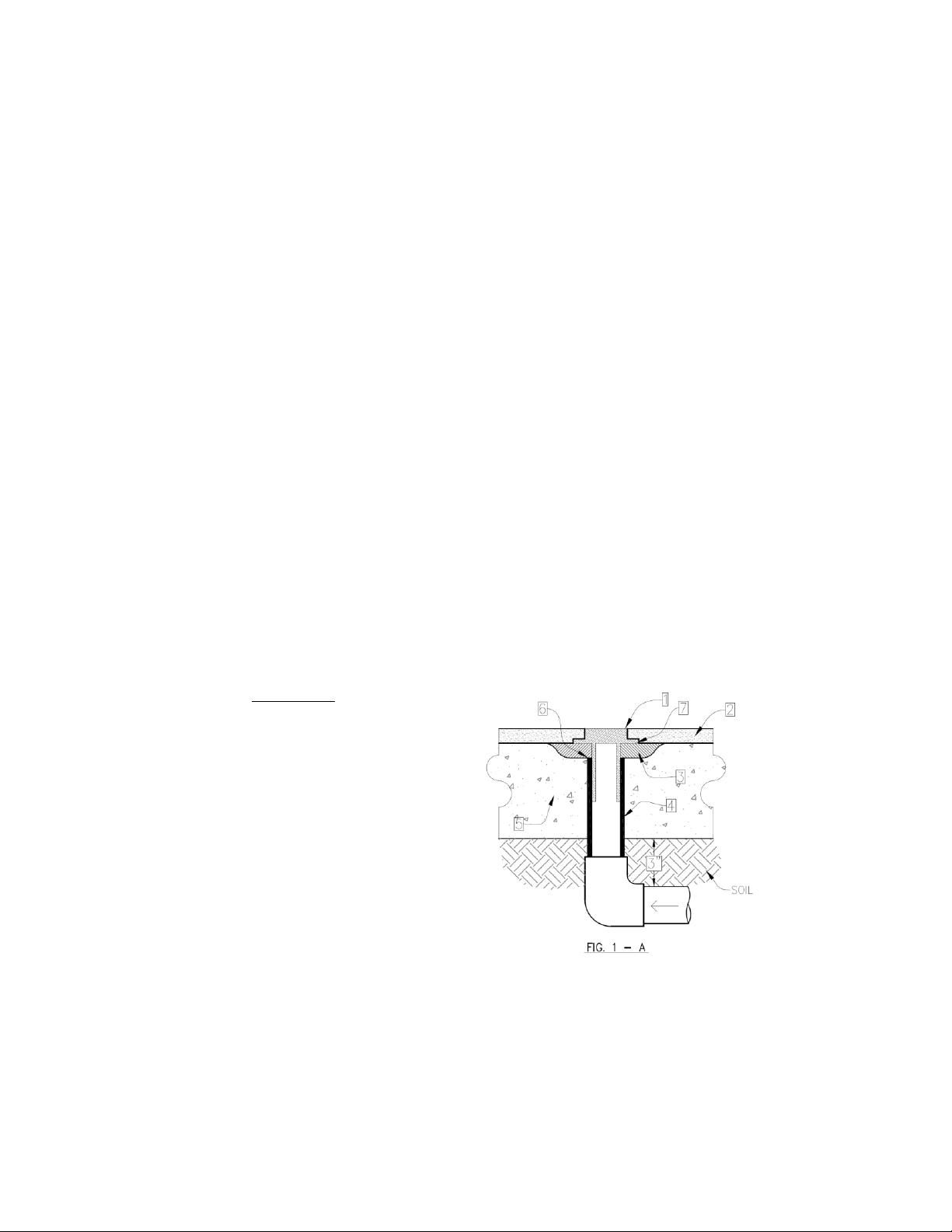
Install Cleaning Collars and Heads
Use inside pipe cutter to cut pipe 1/2" below pool concrete floor.
use Hydraulic cement over and around pipe and up to bottom of flange
(See Fig, 1-A)
Reference:
1. In floor collar
2. Interior pool finish
3. Hydraulic cement
4. 2" P.V.C. Pipe
5. Pool Shotcrete / Gunite
6. Top of Supply pipe 1/2"
below flange
7. Bottom of flange
Page | 9
V14612INSLM
Install Working Valve for Startup (after the pool is filled)
1. Turn pump off at the pool pump.
2. Loosen the bolt on band clamp and remove the band clamp and clear lid.
3. Clean any construction debris from the interior and top edge of the valve
housing.
4. Install the cassette (Gear Train) by sliding it onto the center shaft. Spin the
gears and make sure the cassette drops all the way down and the lower gear
engages with the gear train on the housing perimeter.
5. Place the turbine on the center shaft gear side down. Make sure the gear on
the turbine engages the upper gear on the cassette. Spin the turbine several
times and observe that the white bottom plate is slowly turning. If it does not
the cassette is not in the full “down” position and the lower gear is above the
gear train on the housing perimeter. Push the
cassette down into the gear train if necessary.
6. Check the positioning of large 0-ring and make
sure it is in the groove on the top of the valve
housing. Remove any debris.
7. Align the center shaft on the guide pin hole in the
center of the clear lid and gently push the lid
down. The lid should sit firmly on the top of the
valve housing with no wobble. If it does not sit
firmly remove the turbine and press the cassette
down into the gear train.
8. Replace the band clamp and tighten the bolt
firmly. Do not over tighten.
9. Turn on the system and allow it to cycle until all of
the protective caps are blown free from the collar
and to allow any additional construction debris to
be blown out of the pipes.
10. After the interior finish has properly cured (see the
interior finish manufacturer’s specifications) install
the jets in the collars. Make sure to follow the
design plan for proper locations of High Flow Jets
½ opening, and Low Flow Jets 3/16” nozzle.
Improper nozzle sizes in the wrong location can
cause high pressures and water to be forced out
of the pool onto the deck.
OPERATION AND ROUTINE MAINTENANCE
The Blue Square Q360 cleaning heads are designed to operate at a specific flow rate
and pressure. To ensure proper circulation and or cleaning, run the system whenever the
pump is on.
Cleaning times will vary according to application and environment. To determine the
optimum cleaning time, run the system 24 hours a day after initial startup. Reduce run
times by four hours every two days until minimum cleaning time is determined. Six hours a
day is recommended as a minimum, but pools with high debris conditions often need
longer cleaning cycles.

Page | 10
V14612INSLM
CLEANING THE FILTRATION SYSTEM
For optimum cleaning efficiency, routinely clean the
pump basket, skimmer and filter screens. Backwash or
clean the pool filter whenever pressure increases 5-10 psi
above normal clean-filter operating pressure or if you
notice dirty spots between the jets.
CHANGING CLEANING HEADS
The cleaning jets must be in the full down position before
removal.
1. Attach the Jet Removal Tool to the pool pole
2. Snap tool into the jet
3. Turn counter-clockwise to release head from
collar
4. Pull and lift the jet out of the collar
To reinstall, simply insert head into collar and turn
clockwise to lock into position.
TROUBLESHOOTING
If the Blue Square Q360 cleaning system displays the following actions, adjustments may
be necessary to restore performance. Refer to exploded parts diagram for part
references.
Action: Dirty Spots appear
Solution: Clean the pool filter, pump basket and skimmer baskets.
Make sure all auxiliary valves (surface returns, waterfall, spa overflow, etc.) are closed.
If you have a variable speed pump, check to make sure the pump is running at a
sufficient RPM as recommended by your pool builder.
Action: Dirt is trapped between heads
Solution: Verify that the water flows from the jet nozzle on each side of dirty spot are not
apposing one another. To change the cleaning jet flow direction, press the jet down 5-6
times while it is in the up position and the water is flowing out of the nozzle.
Actions: Cleaning jet advances, but is not cleaning, (dirt remains near the jet.)
Solution: Remove the cleaning jet with the jet removal tool. Check for debris lodged in
the nozzle. Make sure the jet freely travels up and down and ratchets slightly each time.
If the jet does not, hold the jet in the up position and rinse with water to dislodge internal
debris. Run the pump, while the jet is removed, a full cycle until you see water flow out of
the opening on the problem bank. Let the system run without the jet until you are certain
that all of the debris is blown out of the pipe. Re-insert the cleaning jet with the jet
removal tool.
Action: Cleaning jet will not go down
Solution: Try to gently touch the jet with the pool pole to see if it will retract, if the jet
retract let the system run and see the problem is solved. If the problem recurs, remove
the jet with the jet removal tool. Inspect the cleaning head and collar for or debris. Run
the pump, while the jet is removed, a full cycle through the problem bank, to blow out
any debris. Re-insert the cleaning jet. On variable speed pump applications, you may
need to increase RPM’s to ensure jet fully ratchets to next position.

Page | 11
V14612INSLM
To replace the Cassette in the water valve:
1. Turn pump off
2. Loosen the bolt on band clamp and remove the band clamp and clear lid.
3. Remove the turbine and old cassette by sliding them off of the center shaft.
4. Install the new cassette by sliding it onto the center shaft. Spin the gears and make
sure the cassette drops all the way down and the lower gears engage with the gear
train on the housing perimeter.
5. Place the turbine on the center shaft gear side down. Make sure the gear on the
turbine engages the upper gear on the cassette. Spin the turbine several times and
observe the white bottom plate is slowly turning. If it does not the cassette is not in
the full “down” position and the lower gear is above the gear train on the housing
perimeter.
6. Check positioning of large 0-ring on the clear lid.
7. Align the center shaft on the guide pin hole in the center of the clear lid and gently
push the lid down. The lid should seat firmly seat on the top of the valve housing with
no wobble.
8. Replace the band clamp and tighten the bolt firmly. Do not over tighten.
Thank you for purchasing a Blue Square Q360 In-Floor Cleaning System! With over 20
years of pool building and in-floor knowledge, this system was designed with you and the
homeowner in mind. This cost effective and efficient system is truly innovative with a very
simple approach to installation and repair; making it easy for the homeowner to keep
their pool clean and, should there be a problem to arise, easy to fix. We are here to
answer questions, resolve issues and provide exceptional customer service.
Blue Square Manufacturing, LLC
525 East Baseline Road
Suite 107
Gilbert, AZ 85233
Office 480.612.6880 Toll Free 800.277.4150
sales@bluesquaremfg.com
Other manuals for Q360
1
Table of contents


