manuals.online logo
Brands
  1. Home
  2. •
  3. Brands
  4. •
  5. Pentair
  6. •
  7. Control Unit
  8. •
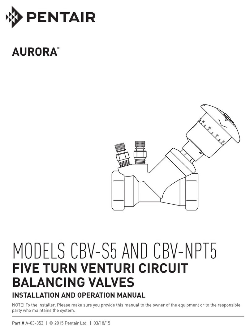
  9. Pentair AURORA CBV-S/A User manual

Pentair AURORA CBV-S/A User manual

NOTE! To the installer: Please make sure you provide this manual to the owner of the equipment or to the responsible
party who maintains the system.
MODELS CBV-S/A
GROOVED: 2.5" – 12"
(DN65 to DN300)
CIRCUIT BALANCING
VALVES – GROOVED
INSTALLATION AND OPERATION MANUAL
Part # A-03-355 | © 2015 Pentair Ltd. | 01/01/15
MODEL CBV-S/A GROOVED
2
ITEM 1040
DATED JANUARY 2015
TYPICAL APPLICATIONS:
CBV-S/A Grooved circuit
balancing valves are rugged,
double regulating valves for
balancing hydronic fluid flow
in HVAC heating and chiller
systems. These valves combine
the functions of positive shut-
off, precise flow regulation,
and variable orifice flow
measurement. Ensure application
requirements are compatible with materials of construction,
temperature and pressure ratings, and flow rate ranges, as
defined in the corresponding product submittals.
CALIFORNIA PROPOSITION 65 WARNING:
This product and related accessories contain
chemicals known to the State of California to cause cancer,
birth defects or other reproductive harm.
VARIABLE VS FIXED ORIFICE FLOW
MEASUREMENT:
CBV-S/A Grooved circuit balancing valves are equipped with
PT ports across the valve seat for basic variable orifice pressure
drop to flow correlation. When installed as prescribed, flow
measurement accuracy to ± 5% is achievable when the valve is
wide open. For higher accuracy, especially at high turndown,
the CBV may be used in conjunction with a fixed orifice
flowmeter. Refer to fixed orifice flowmeter instructions for
additional requirements, if applicable.
LOCATION:
1. The CBV-S/A Grooved may
be installed in vertical or
horizontal piping.
2. Ensure the valve flow
direction arrow matches the
system fluid flow direction.
3. When desired, the valve may be converted to elbow
configuration:
a. To suit physical constraints.
b. To eliminate the need for an additional discrete elbow.
4. For optimum flow measurement accuracy and when
practical, locate the valve:
a. 5 pipe diameters downstream of a fitting.
b. 2 pipe diameters upstream of a fitting.
c. 10 pipe diameters upstream or downstream of a pump.
5. Ensure sufficient clearance is provided for:
a. Handle operation / removal
b. PT port access
c. Drain port access
6. Ensure the valve is mounted
such that the:
a. PT ports are pointing up
so they will not become
clogged with dirt that
may be present in the
hydronic fluid.
b. Drain ports are pointing down so they will effectively
drain fluid from the valve.
c. If necessary, exchange the positions of the PT ports
and drains.
CONVERSION TO ELBOW CONFIGURATION:
To change the valve from straight
to elbow configuration:
1. Open the valve handle one
complete turn.
2. Remove the 4 hex cap bolts
holding the split-case halves
together.
3. Rotate one half of the casing
180 degrees, taking care not to dislodge or damage the
casing O-ring.
4. Ensure the valve halves are properly seated.
5. Insert the 4 hex cap bolts and tighten evenly starting with
opposite corners.
SYSTEM CONNECTIONS:
Before making system connections, ensure adjacent piping is
free and clear of burrs and debris.
1. Grooved Connections:
a. For lowest cost installation and minimum off-axis
loading, Aurora grooved products may be connected to
the system piping (or another component) by the industry
standard groove connections, using any compatible
grooved coupling.
b. Follow the coupling manufacturer’s instructions for
making reliable connections.
2. Flange Adapters:
a. When desired, one or both of the grooved valve
connections may be fitted with an flange adapter as
required to suit the system connections.
b. Place the two halves of the flange adapter onto the
groove.
c. Ensure the tab on the flange adapter is between the two
locking lugs of the valve body.
d. Apply silicone to the inner and outer diameters of the
flange adapter gasket.
e. Press the gasket, printed side in, firmly between the valve
body and flange adapter.
f. Position the assembly to the mating flange, and insert all
flange bolts.
g. Tighten all flange bolts evenly, using a standard flange
tightening pattern.
h. Ensure the flange adapter gasket flat face (not printed)
contacts the mating flange surface squarely.
2D 5D
CBV
CBV
PUMP
2D 10D
MODEL CBV-S/A GROOVED
3
ITEM 1040
DATED JANUARY 2015
i. Flange adapter gaskets are not interchangeable with other
flange adapters.
HANDLE TURNS INDICATOR POSITION:
To adjust the handle turns indicator position to enable easier
access for viewing:
1. Fully close the valve.
2. Remove the handle retaining bolt at the hub of the handle.
3. Pull the handle straight from the valve stem (tap gently with
a soft mallet if required).
4. For models with:
a. Plastic handles; rotate the handle and turns indicator
assembly (retaining a turns indication of 0.0) and replace
the handle onto the valve stem.
b. Cast iron handles; loosen the brass knurled turns indicator
retaining ring, rotate the turns indicator to desired
position, retighten the retaining ring by hand (do not over-
tighten), and replace the handle on the valve stem.
5. Insert and tighten the valve handle retaining bolt.
6. Open the valve to ensure the handle turns freely and turns
indicator reads properly.
OPERATION:
1. If an alternate technology flowmeter is used, refer to the
instructions supplied for taking flow measurements.
2. For variable orifice flow measurement using the differential
pressure developed across the valve seat, remove the PT
Port caps from the valve using caution to avoid contact with
the hydronic fluid.
3. Insert and tighten the manometer high pressure probe to the
PT port closest to supply, and the low pressure probe to the
PT port closest to return.
4. Ensure there are no leaks at any meter probe connections.
5. Take the differential pressure measurement.
6. If the value is negative, ensure the meter connections are not
reversed. Otherwise, check the fluid flow direction in that
piping section.
7. Use the corresponding CBV-S/A Grooved performance
charts or flow calculations to convert the differential
pressure reading to the corresponding flow rate.
8. Adjust the CBV handle as required to read the required
pressure drop measurement, using the appropriate flow
coefficient for the handle setting.
9. When finished, carefully remove the meter probes to
avoid contact with the hydronic fluid, and replace the PT
port caps.
CALIBRATION MEMORY SETTING:
If desired, the memory setting may be used so that if the valve
is throttled or shut off during use or servicing, when the valve
is fully reopened, it returns precisely to the calibrated setpoint.
1. Record the valve handle turns corresponding to the
calibrated setpoint.
2. Remove the handle retaining bolt at the hub of the handle.
3. Pull the handle straight from the valve stem (tap gently with
a soft mallet if required).
4. Without turning the valve stem, for models with:
a. Plastic handles:
i. Turn the plastic memory stop clockwise until it
bottoms (finger tight only).
ii. While holding the memory stop position, turn the lock
collar clockwise until it stops against the valve bonnet.
b. Cast iron handles:
i. Turn the brass memory stop ring until the aluminum
bar contacts the step on the valve stem (finger tighten
only).
5. Replace the handle on the valve stem, ensuring the
previously recorded turns indicator reading and desired
orientation are retained.
6. Insert and tighten the valve handle retaining bolt.
7. Close the valve and then reopen fully, to ensure it turns
freely until it stops at the previously recorded calibration
setpoint.
REPLACING GLAND PACKING UNDER PRESSURE:
CBVs should provide many years of reliable service with little
or no maintenance. However, a regular schedule of inspection
for leaks is recommended. Should the valve gland packing
develop a leak, it can be replaced under pressure, avoiding the
need to depressurize and drain the system, as follows:
1. Always take necessary precautions to avoid contact with
hydronic fluid. Allow the system fluid to adjust to room
temperature if possible, or else exercise extreme caution to
avoid personal injury.
2. Record the valve handle turns corresponding to the
calibrated setpoint.
3. If the calibration memory setting feature has been
used, remove the handle as required to turn the memory
stop fully counterclockwise so that the valve can be
completely opened.
4. Open the valve fully (torque not to exceed 45 ft. lbs.).
5. The metal-to-metal service seal is now engaged. (This is not
a drip-tight seal.)
6. Carefully remove the valve packing nut very slowly,
ensuring system pressure is retained. Some escape of
hydronic fluid is normal. Be careful to avoid contact.
7. Clean the exposed portion of the valve stem, taking care not
to scratch it.
8. Remove the O-ring and gasket and replace with new
and same.
9. Replace the packing nut and tighten as required to ensure a
leak-tight seal.
10. Replace the turns indicator and memory stop mechanisms.
11. Replace the valve handle and tighten the handle
retaining nut.
12. Close the handle slightly while ensuring the valve packing
retains pressure and is drip-free.
13. Ensure the valve closes completely, reading 0.0, and opens
fully (or to the calibrated setpoint if the memory stop feature
is used).
14. Return the valve handle to the calibrated setpoint.
WARRANTY
Seller warrants equipment (and its component parts) of its own manufacture against defects in materials and workmanship under normal use
and service for one (1) year from the date of installation or start-up, or for eighteen (18) months after the date of shipment, whichever occurs
first. Seller does not warrant accessories or components that are not manufactured by Seller; however, to the extent possible, Seller agrees to
assign to Buyer its rights under the original manufacturer's warranty, without recourse to Seller. Buyer must give Seller notice in writing of
any alleged defect covered by this warranty (together with all identifying details, including the serial number, the type of equipment, and the
date of purchase) within thirty (30) days of the discovery of such defect during the warranty period. No claim made more than 30 days after
the expiration of the warranty period shall be valid. Guarantees of performance and warranties are based on the use of original equipment
manufactured (OEM) replacement parts. Seller assumes no responsibility or liability if alterations, non-authorized design modifications
and/or non-OEM replacement parts are incorporated If requested by Seller, any equipment (or its component parts) must be promptly
returned to Seller prior to any attempted repair, or sent to an authorized service station designated by Seller, and Buyer shall prepay all
shipping expenses. Seller shall not be liable for any loss or damage to goods in transit, nor will any warranty claim be valid unless the
returned goods are received intact and undamaged as a result of shipment. Repaired or replaced material returned to customer will be
shipped F.O.B., Seller's factory. Seller will not give Buyer credit for parts or equipment returned to Seller, and will not accept delivery of
any such parts or equipment, unless Buyer has obtained Seller's approval in writing. The warranty extends to repaired or replaced parts of
Seller's manufacture for ninety (90) days or for the remainder of the original warranty period applicable to the equipment or parts being
repaired or replaced, whichever is greater. This warranty applies to the repaired or replaced part and is not extended to the product or any
other component of the product being repaired. Repair parts of its own manufacture sold after the original warranty period are warranted for
a period of one (1) year from shipment against defects in materials and workmanship under normal use and service. This warranty applies to
the replacement part only and is not extended to the product or any other component of the product being repaired. Seller may substitute
new equipment or improve part(s) of any equipment judged defective without further liability. All repairs or services performed by Seller,
which are not covered by this warranty, will be charged in accordance with Seller's standard prices then in effect.
THIS WARRANTY IS THE SOLE WARRANTY OF SELLER AND SELLER HEREBY EXPRESSLY DISCLAIMS AND BUYER
WAIVES ALL OTHER WARRANTIES EXPRESSED, IMPLIED IN LAW OR IMPLIED IN FACT, INCLUDING ANY WARRANTIES
OF MERCHANTABILITY OR FITNESS FOR A PARTICULAR PURPOSE. Seller's sole obligation under this warranty shall be, at its
option, to repair or replace any equipment (or its component parts) which has a defect covered by this warranty, or to refund the purchase
price of such equipment or part. Under the terms of this warranty, Seller shall not be liable for (a) consequential, collateral, special or
liquidated losses or damages; (b) equipment conditions caused by normal wear and tear, abnormal conditions of use, accident, neglect, or
misuse of said equipment; (c) the expense of, and loss or damage caused by, repairs or alterations made by anyone other than the Seller; (d)
damage caused by abrasive materials, chemicals, scale deposits, corrosion, lightning, improper voltage, mishandling, or other similar
conditions; (e) any loss, damage, or expense relating to or resulting from installation, removal or reinstallation of equipment; (f) any labor
costs or charges incurred in repairing or replacing defective equipment or parts, including the cost of reinstalling parts that are repaired or
replaced by Seller; (g) any expense of shipment of equipment or repaired or replacement parts; or (h) any other loss, damage or expense of
any nature.
The above warranty shall not apply to any equipment which may be separately covered by any alternate or special warranties.
PERFORMANCE: In the absence of Certified Pump Performance Tests, equipment performance is not warranted or guaranteed.
Performance curves and other information submitted to Buyer are approximate and no warranty or guarantee shall be deemed to arise as a
result of such submittal. All testing shall be done in accordance with Seller's standard policy under Hydraulic Institute procedures.
LIABILITY LIMITATIONS: Under no circumstances shall the Seller have any liability under the Order or otherwise for liquidated
damages or for collateral, consequential or special damages or for loss of profits, or for actual losses or for loss of production or progress of
construction, regardless of the cause of such damages or losses. In any event, Seller's aggregate total liability under the Order or otherwise
shall not exceed the contract price.
ACTS OF GOD: Seller shall in no event be liable for delays in delivery of the equipment or other failures to perform caused by fires, acts of
God, strikes, labor difficulties, acts of governmental or military authorities, delays in transportation or procuring materials, or causes of any
kind beyond Seller's control.
COMPLIANCE WITH LAW: Seller agrees to comply with all United States laws and regulations applicable to the manufacturing of the
subject equipment. Such compliance shall include: The Fair Labor Standards Acts of 1938, as amended; Equal Employment Opportunity
clauses of Executive Order 11246, as amended; Occupational Safety and Health Act of 1970 and the standards promulgated thereunder, if
applicable. Since compliance with the various Federal, State, and Local laws and regulations concerning occupational health and safety,
pollution or local codes are affected by the use, installation and operation of the equipment and other matters over which Seller has no
control, Seller assumes no responsibility for compliance with those laws and regulations, whether by way of indemnity, warranty, or
otherwise. It is incumbent upon the Buyer to specify equipment which complies with local codes and ordinances.
800 Airport Road
North Aurora, Illinois 60542
630-859-7000
www.aurorapump.com

Other Pentair Control Unit manuals

Pentair FLECK 5800 User manual

Pentair

Pentair FLECK 5800 User manual

Pentair FLECK 9000 SXT User guide

Pentair

Pentair FLECK 9000 SXT User guide

Pentair FLECK 2910 NXT User guide

Pentair

Pentair FLECK 2910 NXT User guide

Pentair SIATA V132 SFE-EV VIRIDION User manual

Pentair

Pentair SIATA V132 SFE-EV VIRIDION User manual

Pentair AURORA 1040 Series Operating instructions

Pentair

Pentair AURORA 1040 Series Operating instructions

Pentair F251 Installation and operating instructions

Pentair

Pentair F251 Installation and operating instructions

Pentair KEYSTONE OM3 User manual

Pentair

Pentair KEYSTONE OM3 User manual

Pentair AUTOTROL368 User guide

Pentair

Pentair AUTOTROL368 User guide

Pentair FLECK 2850 SXT User guide

Pentair

Pentair FLECK 2850 SXT User guide

Pentair JUNG PUMPEN BASICLOGO AD 00 E User manual

Pentair

Pentair JUNG PUMPEN BASICLOGO AD 00 E User manual

Pentair SIATA V132-SFE User manual

Pentair

Pentair SIATA V132-SFE User manual

Pentair HI FLOW SIX-WAY 1-1/2 INCH TOP MOUNT VALVE User manual

Pentair

Pentair HI FLOW SIX-WAY 1-1/2 INCH TOP MOUNT VALVE User manual

Pentair E-Box MAESTRO Lite Operating instructions

Pentair

Pentair E-Box MAESTRO Lite Operating instructions

Pentair Goyen Precision P1 User manual

Pentair

Pentair Goyen Precision P1 User manual

Pentair 2750 User manual

Pentair

Pentair 2750 User manual

Pentair Goyen Mecair FFA User manual

Pentair

Pentair Goyen Mecair FFA User manual

Pentair PROSTOP-E User manual

Pentair

Pentair PROSTOP-E User manual

Pentair JUNG PUMPEN BASICLOGO BD User manual

Pentair

Pentair JUNG PUMPEN BASICLOGO BD User manual

Pentair Hydromatic Novus 4000 Manual

Pentair

Pentair Hydromatic Novus 4000 Manual

Pentair Keystone Figure 952 NPS 2 Installation instructions

Pentair

Pentair Keystone Figure 952 NPS 2 Installation instructions

Pentair AUTOTROL 363 User manual

Pentair

Pentair AUTOTROL 363 User manual

Pentair FLECK 5810 User manual

Pentair

Pentair FLECK 5810 User manual

Pentair E-Box MAESTRO Operating instructions

Pentair

Pentair E-Box MAESTRO Operating instructions

Pentair Fleck 9000-SXT User manual

Pentair

Pentair Fleck 9000-SXT User manual

Popular Control Unit manuals by other brands

V2 Easy 3 manual

V2

V2 Easy 3 manual

DeZurik VPB V-PORT instruction manual

DeZurik

DeZurik VPB V-PORT instruction manual

Celtic tuning eMotion installation manual

Celtic tuning

Celtic tuning eMotion installation manual

Honeywell VC Series installation instructions

Honeywell

Honeywell VC Series installation instructions

Orion Dew Zapper Pro manual

Orion

Orion Dew Zapper Pro manual

White Rodgers 1127 installation instructions

White Rodgers

White Rodgers 1127 installation instructions

Siemens SIRIUS 3RT manual

Siemens

Siemens SIRIUS 3RT manual

LEGRAND EMDX AMS manual

LEGRAND

LEGRAND EMDX AMS manual

Bartec 07-61.1 Series Operational Instruction

Bartec

Bartec 07-61.1 Series Operational Instruction

Enerpac VP Series instruction sheet

Enerpac

Enerpac VP Series instruction sheet

tau D820M installation guide

tau

tau D820M installation guide

Grundfos MIXIT manual

Grundfos

Grundfos MIXIT manual

IKA CBC 5 control operating instructions

IKA

IKA CBC 5 control operating instructions

Maestro Wireless Solution A5100-A user manual

Maestro Wireless Solution

Maestro Wireless Solution A5100-A user manual

WebWay Nano WiFi quick start guide

WebWay

WebWay Nano WiFi quick start guide

Yoshitake OB-3 manual

Yoshitake

Yoshitake OB-3 manual

Jetter JXM-IO-EW30-G27 user manual

Jetter

Jetter JXM-IO-EW30-G27 user manual

WAGO 750-363/0040-0000 manual

WAGO

WAGO 750-363/0040-0000 manual

manuals.online logo
manuals.online logoBrands
  • About & Mission
  • Contact us
  • Privacy Policy
  • Terms and Conditions

Copyright 2025 Manuals.Online. All Rights Reserved.