Blue Wave NE9882 User manual

V1: 1021
SKU# NE9881, NE9882
FLOWXTREME™
PRO VS II VARIABLE
SPEED POOL PUMPS
FOR ABOVE/IN-GROUND POOLS
Questions, problems, missing parts?
Before returning to your retailer, call our Consumer Hotline at 1-800-759-0977,
Monday – Friday. 8am – 5pm (CST)

TABLE OF CONTENTS
THANK YOU! ............................................................................................................................................ 3
SAFETY INFORMATION ........................................................................................................................... 3
SAFETY INSTRUCTIONS & WARNING .................................................................................................... 3
GENERAL INSTALLATION INSTRUCTIONS ............................................................................................ 7
ELECTRICAL & WIRING INSTRUCTIONS ................................................................................................ 9
START-UP & OPERATIONS ....................................................................................................................... 11
PROGRAMMING VARIABLE TIME & SPEED OPERATIONS .................................................................... 13
MAINTENANCE, STORAGE & WINTERIZATION..................................................................................... 16
TECHNICAL DATA FOR FX PRO VS II ABOVE-GROUND & IN-GROUND PUMPS ................................ 17
TROUBLESHOOTING FOR FX PRO VS II PUMPS .................................................................................... 20
POOL PUMP TROUBLESHOOTING GUIDELINES .................................................................................. 21
WARRANTY INFORMATION..................................................................................................................... 24

3
THANK YOU!
SAFETY INFORMATION
1. SAFETY INSTRUCTIONS & WARNINGS
Thank you for purchasing this product. You have purchased a high quality replacement pump from
Blue Wave. All pumps covered in this manual have full-rated motors and have been manufactured and
tested to offer many years of trouble-free service. We work around the clock and around the globe
to ensure that our products maintain the highest possible quality. However, in the rare case of issues
during assembly or use of this product, please contact our Consumer Hotline at 800-759-0977 for
immediate assistance before contacting your retailer. Please read the warranty information at the back
of these assembly instructions for further details.
Please read this entire manual before attempting to assemble, operate or install the product. Save
this instruction manual for future use. This manual contains important information regarding the safe
use, operation, and installation of this pump. The use of unauthorized replacement parts voids the
warranty.
To prevent serious injury and to avoid unnecessary service calls, read this manual carefully
and completely.
WARNING
CAUTION
To reduce risk of injury, do not permit children to use or climb on this product.
Closely supervise children at all times. Components such as the ltration
system, pumps, and heaters must be positioned to prevent children from using
them as a means of access to the pool.
This pump is intended for use on permanently installed in-ground or above-
ground swimming pools and may also be used with hot tubs and spas if so
marked. Do NOT use with storable pools. A permanently installed pool is
constructed in- or on-the-ground or in a building such that it cannot be readily
disassembled for storage. A storable pool is constructed so that it is capable of
being readily disassembled for storage and reassembled to its original integrity.
Though this product is designed for outdoor use, it is strongly advised to
protect the electrical components from the weather. Select a well-drained area,
one that will not ood when it rains. It requires free circulation of air for cooling.
Do not install in a damp or unventilated location. If installed within an outer
enclosure or beneath the skirt of a hot tub or spa, adequate ventilation and free
circulation of air must be provided to prevent overheating of the motor.
NOTICE

4
1. SAFETY INSTRUCTIONS (CONTINUED)
WARNING Some pump components have a nite life. All components should be inspected
frequently and replaced if found to be worn, damaged, broken, cracked, or
missing.
Risk of Electric Shock.
Hazardous voltage. Can shock, burn, or cause death. To reduce the risk of
electric shock, do NOT use an extension cord to connect unit to electric supply.
Provide a properly located outlet. It is required that licensed electricians do all
electrical wiring. All electrical wiring MUST be in conformance with applicable
local and national codes and regulations. Before working on pump or motor,
disconnect motor wiring.
WARNING
WARNING Do NOT bury cord. Place the cord on the ground so it can avoid abuse from
lawn mowers, hedge trimmers and other equipment.
Connect only to a grounding type receptacle protected by a Ground Fault
Circuit Interrupter (GFCI). Contact a licensed electrician if you cannot verify that
the receptacle is protected by a GFCI.
Failure to bond pump to pool structure will increase risk for electrocution
and could result in injury or death. To reduce the risk of electric shock, see
installation instructions and consult a professional electrician on how to bond
pump.
Also, contact a licensed electrician for information on local electrical codes
for bonding requirements. Use a solid copper conductor, size 8 or larger.
Run a continuous wire from external bonding lug to reinforcing rod or mesh.
Connect a No. 8 AWG (8.4 mm2) solid copper bonding wire to the pressure wire
connector provided on the motor housing and to all metal parts of swimming
pool, spa, or hot tub, and to all electrical equipment, metal piping (except gas
piping), and conduit within 5 ft. (1.5m) of inside walls of swimming pool, spa, or
hot tub.
IMPORTANT - Reference NEC codes for all wiring standards including, but not
limited to, grounding, bonding, and other general wiring procedures.
NOTE - The National Electrical Code (NEC) permits use of a cord with a
maximum 3 ft. (1 m) length. If your pump is equipped with a cord complying
with the NEC, the preceeding four (4) hazards apply.
WARNING
WARNING
WARNING
WARNING
Failure to install according to dened instructions may result in severe personal
injury or death.
Use of unauthorized replacement parts voids warranty.

5
1. SAFETY INSTRUCTIONS (CONTINUED)
Suction Entrapment Hazard. Entrapment in suction outlets and/or suction
outlet covers, which are damaged, broken, cracked, missing, or unsecured can
cause severe injury and/or death due to the following entrapment hazards:
Hair Entrapment- Hair can become entangled in suction outlet cover.
Limb Entrapment- A limb inserted into an opening of a suction outlet sump or
suction outlet cover that is damaged, broken, cracked, missing, or not securely
attached can result in a limb becoming entrapped.
Body Suction Entrapment- Pressure applied to a large portion of the body or
limbs can result in an entrapment.
Mechanical Entrapment- There is potential for jewelry, swimsuits, hair
decorations, ngers, toes, or knuckles to be caught in an opening of a suction
outlet cover resulting in mechanical entrapment.
WARNING
WARNING Reduce the risk of Entrapment Hazards:
- When outlets are small enough to be blocked by a person, a minimum of two
functioning suction outlets per pump must be installed. Suction outlets in the
same plane (i.e. oor or wall), must be installed a minimum of three feet (3’)
[0.91 meter] apart, as measured from near point to near point.
- Dual suction ttings shall be placed in such locations and distances to avoid
“dual blockage” by a user.
- Dual suction ttings shall not be located on seating areas or on the backrest
for such seating areas.
- The maximum system ow rate shall not exceed the values shown in the “Pipe
Sizing Chart” found at the bottom of page 7 of this manual.
-Never use pool if any suction outlet component is damaged, broken, cracked,
missing, or not securely attached.
- Replace damaged, broken, cracked, missing, or not securely attached suction
outlet components immediately.
- In addition to two or more suction outlets per pump installed in accordance
with latest IAF (formerly NSPI) standards and CPSC guidelines, follow all
national, state, and local codes applicable.
- Installation of a vacuum release or vent system, which relieves entrapping
suction, is recommended.
WARNING Fire and burn hazard.
Motors operate at high temperatures and if they are not properly isolated from
any ammable structures or foreign debris they can cause res, which may
cause severe personal injury or death. It is also necessary to allow the motor to
cool for at least 20 minutes prior to maintenance to minimize the risk for burns.

6
1. SAFETY INSTRUCTIONS (CONTINUED)
Hazardous Pressure.
Pool water circulation systems operate under hazardous pressure during
start-up, normal operation, and after pump shut-off. Stand clear of circulation
system equipment during pump start-up. Failure to follow safety and operation
instructions could result in violent separation of the pump housing and cover
due to pressure in the system, which could cause property damage, severe
personal injury, or death. Before servicing the pool water circulation system,
all system and pump controls must be in the off position. The lter manual air
relief valve must be in the open position if it is part of the ltration system.
Before starting system pump, all system valves must be set in a position to
allow system water to return back to the pool. Do not change lter control valve
position while system pump is running. Before starting system pump, fully open
lter manual air relief valve. Do not close lter manual air relief valve until a
steady stream of water (not air or air and water) is discharged. All suction and
discharge valves MUST be OPEN when starting the circulation system.
Failure to do so could result in severe personal injury and/or property damage.
WARNING
Separation Hazard.
Failure to follow safety and operation instructions could result in violent
separation of pump components. Strainer cover must be properly secured to
pump housing with strainer cover lock ring. Before servicing the pool and spa
circulation system, all system and pump controls must be in the off position and
the lter manual air relief valve must be in the open position. Do not operate
pool circulation system if a system component is not assembled properly,
damaged, or missing. Do not operate pool circulation system unless lter air
relief valve body is in closed position. All suction and discharge valves MUST be
OPEN when starting the circulation system.
Failure to do so could result in severe personal injury and/or property damage.
WARNING
WARNING NEVER operate or test the circulation system at more than 40 PSI.
7
2. GENERAL INSTALLATION INSTRUCTIONS
WARNING This product should be installed and serviced by a qualied professional only.
PUMP LOCATION
Place pump as close to pool as practical and run suction lines as direct as possible to reduce friction
loss. Suction lines should have continuous slope upward from lowest point in line. Joints must be
tight (but not over-tightened). Suction line diameter must equal or be larger than the discharge line
diameter. Though the pump is designed for outdoor use, it is strongly advised to protect the electrical
components from the weather. Select a well-drained area, one that will not ood when it rains.
Do NOT install pump in a damp or non-ventilated location. Keep motor clean.
PUMP MOUNTING
Install pump on a rm, level base or pad to meet all local and national codes. Fasten pump to base or
pad with screws or bolts to further reduce vibration and stress on pipe or hose joints. The base MUST
be solid, level, rigid, and vibration free.
Pump installation should:
• Allow pump inlet height to be as close to water level as possible for in-ground pump installations.
• Allow use of short, direct intake pipe or hose (to reduce friction losses).
• Allow for gate valves in intake and discharge pipes for in-ground pump installations.
• Be protected from excess moisture and ooding.
• Allow adequate access for servicing pump and plumbing.
• Installation of union ttings in front of the pump intake and between the pump outlet and tank is
highly recommended for use with in-ground pools.
PIPE SIZING CHART
It is recommended that a minimum length of piping, equivalent to 10 pipe diameters, be
used between the pump suction inlet and any plumbing ttings.
NOTICE
Maximum Recommended System Flow Rate by
Pipe Size for NE9881
Maximum Recommended System Flow Rate by
Pipe Size for NE9882
Pipe Size Flow Rate Pipe Size Flow Rate
[mm] GPM[Liters/Min] [mm] GPM[Liters/Min]
1-1/4” 48 2” 81
[40] [180] [63] [308]
2” 81
[63] [307]

8
2. GENERAL INSTALLATION INSTRUCTIONS
WARNING Hazardous Pressure.
Pumps, lters, and other equipment/components of a swimming pool ltration
system operate under pressure. Incorrectly installed and/or improperly tested
ltration equipment and/or components may fail resulting in injury and/or
property damage.
PLUMBING
Use “Teon” tape, available at any plumbing or hardware store, to seal threaded connections on
molded plastic components. All plastic ttings must be new or thoroughly cleaned before use.
NOTE - Do NOT use Plumber’s Pipe Dope as it may cause cracking of the plastic components.
When applying “Teon” tape to plastic threads, wrap the entire threaded portion of the male tting
with one to two layers of tape. Wind the tape clockwise as you face the open end of the tting,
beginning at the end of the tting. The pump suction and outlet ports have molded-in thread stops.
Do NOT attempt to force hose connector tting past this stop. It is only necessary to tighten
ttings enough to prevent leakage. Tighten tting by hand and then use a tool to engage tting an
additional 1 ½ turns. Use care when using Teon tape as friction is reduced considerably; Do NOT
over-tighten tting or you may cause damage. If leaks occur, remove tting, clean off old Teon
tape, re-wrap with one to two additional layers of Teon tape, and re-install tting. See the Trouble
Shooting section for additional solutions.
FITTINGS
Different pumps come with different types and sizes of hoses or plumbing ttings. Review the
Technical Sections in this Owners / Installation manual to ensure you have the correct tting
before starting installation. If your new pump is replacing an older pump it may be necessary to
nd specialized plumbing tting to make the plumbing connections. Check with your local pool
professional store or a well-equipped hardware store to nd what you need. Fittings restrict ow.
For better efciency, use the fewest possible ttings (but at least two suction outlets). Avoid ttings
that could cause an air trap. Pool ttings MUST conform to the International Association of Plumbing
and Mechanical Ofcials (IAPMO) standards. Use a non-entrapping suction tting in pool (multiple
drains) or double suction (skimmer and main drain).

9
3. ELECTRICAL & WIRING
WARNING Ground and bond the motor before connecting to an electrical power supply.
Failure to ground and bond pump motor can cause a serious or fatal electrical
shock. See section below for Grounding and Bonding instructions.
WARNING
WARNING
WARNING
WARNING
Do NOT ground to a gas supply line.
To avoid dangerous or fatal electrical shock, turn OFF power to motor before
working on electrical connections.
Ground Fault Circuit Interrupter (GFCI) tripping indicates electrical problem. If
GFCI trips and won’t reset, consult electrician to inspect and repair electrical
system.
Fire Hazard.
Match supply voltage to motor nameplate voltage.
Ensure that the electrical supply available agrees with the motor’s voltage,
phase, and cycle, and that the wire size is adequate for the H.P. (KW) rating
and distance from the power source. NOTE - All electrical wiring MUST be
performed by a licensed electrician, and MUST conform to local codes and
NEC regulations. Use copper conductors only.
VOLTAGE
Voltage at motor MUST NOT be more than 10% above or below motor name plate rated voltage, or
motor may overheat, causing overload tripping and reduced component life. If voltage is less than
90% or more than 110% of rated voltage when motor is running at full load, consult Power Company.
Grounding and Bonding
Install, ground, bond, and wire motor in accordance with local or national electrical code
requirements.
Permanently ground motor. Use green ground terminal provided under motor canopy or access place;
use size and type wire required by code. Connect motor ground terminal to electrical service ground.
Bond motor to pool structure. Bonding will connect all metal parts within and around the pool with a
continuous wire.
Bonding reduces the risk of a current passing between bonded metal objects, which could potentially
cause electrical shock if grounded or shorted. Reference NEC codes for all wiring standards
including, but not limited to, grounding, bonding, and general wiring procedures.
Use a solid copper conductor, size 8 or larger. Run wire from external bonding lug to reinforcing rod
or mesh. Connect a No. 8 AWG (8.4 mm2) solid copper bonding wire to the pressure wire connector
provided on the motor housing and to all metal parts of swimming pool, and to all electrical
equipment, metal piping (except gas piping), and conduit within 5 ft. (1.5 m) of inside walls of
swimming pool, spa, or hot tub.
10
3. ELECTRICAL & WIRING
EXTERNAL WIRING
FX PRO VS II In-Ground Pumps MUST be permanently connected to an appropriate electrical circuit.
If other lights or appliances are also on the same circuit, be sure to add their amp loads before
calculating wire and circuit breaker sizes. Use the load circuit breaker as the Master On-Off switch.
Always Install a Ground Fault Circuit Interrupter (GFCI) in circuit; it will sense a short circuit to ground
and disconnect power before it becomes dangerous to pool users. For size of GFCI required and
test procedures for GFCI, see manufacturer’s instructions. In case of a power outage, check GFCI for
tripping, which will prevent normal pump operation. Reset if necessary.
WARNING All wiring must be done by a licensed electrician.
See specic wiring instructions in the Technical Data sections for each pump
covered by this manual.
Above Ground FX PRO VS II pump has pre-attached power cords with 3
prong grounded plugs. If local electrical codes call for power cords with twist
lock plugs, please check with your local professional pool store or online for
availability.
If you do not use conduit when wiring motor, be sure to seal wire opening on the back
end of the motor to prevent dirt, bugs, etc., from entering
NOTICE
NOTICE Model # NE9881, 115V pump comes with a 3-ft, 3 prong grounded power cord attached.
Never use an extension cord to connect a pump with a pre-wired cord to the circuit. You
must bring a permanent outlet with GFCI protection to the location of the pump.
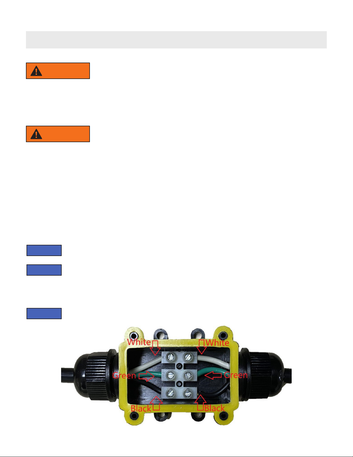
WIRING DIAGRAMS FOR NE9882, 230V PUMP
NOTICE Never disconnect or change locations of any factory installed wires. This will result in
voiding your warranty.
WARNING NEVER open the motor housing to make changes to the factory installed
external power cord. If you attempt to do so it will void your warranty. If the
cord on the pump you purchased is not compatible with your local electrical or
building cords, you must return it to your retailer and purchase a different style
pump.

11
3. ELECTRICAL & WIRING
4. START-UP & OPERATIONS
PRIOR TO START-UP
If it is necessary to perform a pressure test, prior to initial use to ensure pump is
functioning properly, then the following criteria should be maintained for this test:
1. Have a professional perform this test.
2. Ensure all pump and system components are sealed properly to prevent leaks.
3. Remove any trapped air in the system by fully opening lter manual air relief valve until a steady
stream of water is discharged.
4. Allow no more than 40 psi (276 kPa) at a water temperature no higher than 100°F(38°C).
5. Run pressure test for no longer than 24 hours. Immediately inspect all parts to verify they are intact
and functioning properly. Fill strainer housing with water to suction pipe level. NEVER OPERATE THE
PUMP WITHOUT WATER. Water acts as a coolant and lubricant for the mechanical shaft seal.
NOTICE
WARNING If pump is being pressure tested (40 PSI MAXIMUM), be sure pressure has been
released before removing strainer cover.
12
4. START-UP & OPERATIONS
CAUTION NEVER run the pump dry. Running it dry may damage seals, cause leakage or
ooding, and it voids the warranty. Fill the strainer housing with water before
starting the motor.
ATTENTION Do NOT add chemicals to pool system through the skimmer (if pool is so
equipped) or directly in front of pump suction. Adding undiluted chemicals may
damage pump and voids the warranty.
Before removing strainer cover:
1. STOP PUMP before proceeding.
2. CLOSE VALVES in intake and outlet pipes if part of the pump installation.
3. RELEASE ALL PRESSURE from pump and piping system using lter manual
air relief valve. See lter owner’s manual for more detail.
ATTENTION
PRIMING PUMP
All suction and discharge valves MUST be OPEN, as well as lter air relief valve
(if available) on lter, when starting the circulating pump system. Failure to do
so could result in severe injury.
• Release all pressure from lter, pump, and piping system. See lter owner’s manual.
• If the water source is higher than the pump, as is normal with above-ground installation, pump will
prime itself when suction and outlet valves are opened.
• If the water source is lower than the pump, as is normal with in-ground installation, unscrew and
remove strainer cover; ll strainer housing with water.
• Clean and lubricate strainer cover O-ring with high quality O-ring lubricant each time it is removed.
• Inspect O-ring and re-install on strainer cover if damaged.
• Replace strainer cover on strainer housing; turn clockwise to tighten cover.
• NOTE - Tighten strainer cover by hand only (no wrenches).
CAUTION
PRIMING PUMP (CONTINUED)
Now, turn on power and wait for pump to prime, which may take up to ve (5) minutes. Priming time
will depend on vertical length of suction lift and horizontal length of suction pipe. If pump does NOT
prime within ve minutes, stop motor and determine cause. Be sure all suction and discharge valves
are open when pump is running. See Troubleshooting Guide.
Wait ve (5) seconds before re-starting pump.
Failure to do so may cause reverse rotation of motor and consequent serious
pump damage.
Close lter manual air relief valve after pump is primed.
ATTENTION

13
5. PROGRAMMING VARIABLE TIME & SPEED OPERATIONS
Follow the programming steps in this section carefully. Take your time so you complete the
programming successfully the rst time. It is helpful to have a second person to read the
programming steps from the manual as you enter the values with the operation buttons.
A. Operating modes:
These pumps have two operation modes: Manual and Automatic. You can switch
back and forth for your preferred operating mode. To switch between modes, press the
“UP” and “DOWN” buttons at the same time.
1.0) MANUAL OPERATING MODE:
(Image #1)
*In Manual Mode, the pump runs at the constant speed set by the user. (See Image #1)
1.1) Manual mode has four default speeds : “LOW”, “MEDIUM”, “HIGH”, “FULL”
1.2) The default speeds cannot be changed. However, you can adjust to a temporary pump
speed within a default setting with the “UP” or “DOWN” buttons.
1.3) Once you have the temporary speed set, press the “SET” button to adjust to
next default speed.
1.4) In Manual mode, if you turn off the pump, the current speed can be auto-saved when you
use the pump next time.
2.0) AUTOMATIC OPERATING MODE:
• To start Automatic Mode Programing press “SET” once (See Image #2).
- Automatic Mode will not function until Current Time and Times & Speeds Parameters
are programmed. Follow the instructions below to program Current Time and the Times & Speeds
Parameters for each segment.
(Image #2)
NOTICE
Speed Table Low Medium High Full
Lowest Speed 1150 1150 1150 1150
Highest Speed 3450 3450 3450 3450
Default Speed 1150 1700 2800 3450

14
5. PROGRAMMING VARIABLE TIME & SPEED OPERATIONS
2.1) PROGRAM CURRENT TIME:
• To set Current Time press the “RUN/STOP” and “SET” button at the same time, hold for 3 seconds.
The hour setting will ash. Use the “UP” or “DOWN” buttons to adjust to current hour. When you
have the hour correct press the “SET” button once to move to minute setting. The minute setting will
ash. Press the “UP” or “DOWN” button to adjust to the current minute (See Image #3).
(IMAGE #3)
2.2) PROGRAM “T” SEGMENT TIMES AND OPERATING SPEEDS:
• A maximum of 4 timing segments can be programmed. Each timing segment includes three
parameters: “Start Time,” “End Time,” and “Running Speed”. The segments are shown on the
screen as “T1,” “T2,” “T3,” and “T4”. After setting, the pump runs at the speed programmed within
the times set for Start and End. Times and speeds are saved when power is off.
• When programming time and speed parameters for the rst time, programming automatically starts
with the rst time and speed segment, “T1”.
• When programming a time and speed segment, all parameters (Start Time, End Time and
Running Speed) are displayed. The parameter being programmed ashes.
• Press the “SET” button to start programming your “T1” operating time and speed segment.
Use the “UP” or “DOWN” buttons to program the Start Time, End Time, and Operating Speed.
The parameter being set will ash. When you have the time or speed set as you want, press “SET” to
save it. The next parameter will ash. Continue through the Start Time, End Time, and Speed settings
until nished. Once you have the rst segment programmed press the “SET” button for 3 seconds to
save and exit that segment.
• Press the “DOWN” button to move to the “T2” segment you wish to program. Repeat the
process used to program the rst time and speed segment.
• Continue the process through “T3” & “T4” until you have programmed as many of the four
available time and speed segments you wish. It is not necessary to program all four of the time
and speed segments.
• If you make a mistake while you are programming time and speed in a segment you can go
back by pressing “SET” once. Then switch to the time or speed setting you want to change by
pressing “SET” until that setting ashes. Use the “UP” or “DOWN” buttons to change the setting.

15
5. PROGRAMMING VARIABLE TIME & SPEED OPERATIONS
• If during the process of programming a “T” segment you fail to press a button and more than 8
seconds elapses, the programming for that “T” segment will automatically save and exit. You can
cycle back to that segment by pressing the “DOWN” button once then press the “SET” button
until you come back to the segment you were programming. Proceed with the normal segment
programing steps.
• When programming a “T2,” “T3,” or T4” segment the programmed times may not overlap with
times from other segments. If this happens, the programming for that segment cannot be saved. Go
back to restart that segment’s programming as explained above.
• To fast delete the current settings for “T” segment, set the hour in start time to “23” and press the
“UP” button once, the setting under this segment will be deleted. Or, set the hour in start time to
“00” and press the “Down” button once, the setting under this segment will be deleted.
• Review the button functions below for additional programming information.
3.0) BUTTON DESCRIPTION AND FUNCTIONS:
(Diagram 4)
3.1) “RUN/STOP” BUTTON:
Used to start or stop the pump.
• When switched to stop in the Manual Mode the pump stops until turned back on.
• When switched to stop in the Automatic Mode the pump automatically turns on when the time
reaches the next programmed segment.
3.2) “SET” BUTTON:
• In the Manual Mode, it is used to switch between different default speeds.
• In Automatic Mode, it is used to enter the programming status or enter the next item for
programming in each segment.
• In Automatic Mode press and hold for 3 seconds to exit the segment.
3.3) “UP” BUTTON:
• In Manual Mode, it can be used to increase the pump speed.
• When used during Current Time programming, users can cycle up to the previous interface to view
the timing item page.
• When used in programming the Automatic Mode “T” segments, it is used to increase the time or
speed in that segment.
• Pressing and holding will rapidly increase the change in value.

16
5. PROGRAMMING VARIABLE TIME & SPEED OPERATIONS
3.4) “DOWN” BUTTON:
• In Manual Mode, it can be used to decrease the pump speed.
• When used during Current Time programming, users can cycle down to the previous interface to
view the timing item page.
• When used in programming the Automatic Mode “T” segments, it is used to decrease the time or
speed in that segment.
• Pressing and holding will rapidly decrease the change in value.
3.5) “COMBINATION” BUTTON FUNCTIONS:
• Press the “UP” and “DOWN” buttons at the same time to switch between “Automatic mode” and
“Manual mode”.
• Press the “RUN/STOP” button and “Set” button at the same time and hold for 3 seconds to set the
current time. If you need to cancel the setting, press the “On / Off” button and “Set” button again to
exit.
6. MAINTENANCE/STORAGE & WINTERIZATION
MAINTENANCE
• Clean strainer basket regularly. Do NOT strike basket to clean. Inspect strainer cover gasket
regularly and replace as necessary.
• Pumps have self-lubricating motor bearings and shaft seals. No lubrication is necessary.
• Keep motor clean. Do NOT use water to hose off motor.
• Occasionally, shaft seals must be replaced, due to wear or damage. Replace with genuine seal
assembly kit.
STORAGE & WINTERIZATION
WARNING Separation or Explosion Hazard.
• Do not purge the system with compressed air. Purging the system with
compressed air can cause components to explode, with risk of severe injury
or death to anyone nearby. Use only a low pressure (below 5 PSI), high volume
blower when air purging the pump, lter, or piping.
ATTENTION Use ONLY propylene glycol as antifreeze in your pool/spa system. Propylene
glycol is nontoxic and will not damage plastic system components; other anti-
freezes are highly toxic and may damage plastic components in the system.
• Drain all water from pump and piping when expecting freezing temperatures
or when storing pump for a long time (see instructions below).
• Keep pump dry and covered during storage. To avoid condensation/corrosion
problems, do NOT cover or wrap pump with plastic lm or bags.
Allowing the pump to freeze will void the warranty.
ATTENTION

17
6. MAINTENANCE/STORAGE & WINTERIZATION
STORING PUMP FOR WINTERIZATION
WARNING To avoid a dangerous or fatal electrical shock, turn OFF power to motor before
draining pump. Failure to disconnect power may result in serious personal injury
or death.
• Drain water level below all inlets to the pool.
• Remove drain plugs from bottom of strainer body, and remove strainer cover
from strainer housing.
• Disconnect pump from mounting pad, wiring system, and plumbing system.
• Once the pump is empty of water, re-install the strainer cover and drain plugs.
Store pump in a dry area.
7. TECHNICAL DATA FOR FX PRO VS II
FOR ABOVE-GROUND & IN-GROUND POOL PUMPS
DATA FOR MODEL #’s NE9881 & NE9882:
BW No. Input
Power WEF Voltage Hertz HHP Max Flow
Rate Amps Wire Size
NE9881 1 HP 9.266 115 V 60Hz 0.526
2880 GPH with
1-1/2” Hose
6.4A 12AWG
4863 GPH with
2” Pipe
NE9882 1 HP 10.34 230V 60Hz 0.533 4876 GPH 3.3A 12AWG

18
7. TECHNICAL DATA FOR FX PRO VS II
PUMP PARTS DIAGRAM
1. Pumps Parts Breakdown & Diagram MODEL #: NE9881
PARTS LIST - FX PRO VS 115V
#Part Description QTY. MFG No. BW No. For Model #
1Plastic Nut 2PM2101 NEP20232 NE9881 & NE9882
2-1 Hose Coupling 1-1/2” 2 PM21021 NEP20242 NE9881
2-2 Hose Coupling 2” 2 PM21022 NEP20233 NE9881 & NE9882
3Intake and Discharge O-Ring 2PM2103 NEP20234 NE9881 & NE9882
4Motor Shell 1PM2104 NEP20235 NE9881 & NE9882
5Drain Plug O-Ring 2PM2105 NEP20236 NE9881 & NE9882
6Drain Valve 2PM2106 NEP20237 NE9881 & NE9882
7Screw Cap 1PM2107 NEP20238 NE9881 & NE9882
8Transparent Cover 1PM2108 NEP20239 NE9881 & NE9882
9Pump Lid O-Ring 1PM2109 NEP20240 NE9881 & NE9882
10 Filter Basket 1PM2110 NEP20241 NE9881 & NE9882
11 Power Cord 1PM2111 NEP20243 NE9881

19
7. TECHNICAL DATA FOR FX PRO VS II
PUMP PARTS DIAGRAM
2. Pumps Parts Breakdown & Diagram MODEL #: NE9882
PARTS LIST - FX PRO VS 230V
#Part Description QTY. MFG No. BW No. For Model #
1Plastic Nut 2PM2101 NEP20232 NE9881 & NE9882
2Hose Coupling 2” 2 PM21022 NEP20233 NE9881 & NE9882
3Intake and Discharge O-Ring 2PM2103 NEP20234 NE9881 & NE9882
4Motor Shell 1PM2104 NEP20235 NE9881 & NE9882
5Drain Plug O-Ring 2PM2105 NEP20236 NE9881 & NE9882
6Drain Valve 2PM2106 NEP20237 NE9881 & NE9882
7Screw Cap 1PM2107 NEP20238 NE9881 & NE9882
8Transparent Cover 1PM2108 NEP20239 NE9881 & NE9882
9Pump Lid O-Ring 1PM2109 NEP20240 NE9881 & NE9882
10 Filter Basket 1PM2110 NEP20241 NE9881 & NE9882
11 Power Cord Transfer Box 1PM2211 NEP20244 NE9882

20
8. TROUBLESHOOTING FOR FX PRO VS II PUMPS
COMPUTER CONTROLLED TROUBLE SHOOTING FEATURES for FX PRO VS II PUMPS:
1. High or Low Temperature Protection
When the motor temperature is higher than 194°F or is lower than 23°F, the pump will stop and the
error code TP is displayed. When normal motor temperature is restored, between 41°F to 140°F, the
pump will start automatically according to user’s automatic mode programming.
2. Blocking or Jamming Protection
When the motor impeller or the motor is stuck, the error code BP is displayed. The pump will
automatically attempt to restart in 6 seconds. If restarting does not happen automatically after several
attempts users need to check the impeller and motor. Always turn off power before attempting
maintenance.
3. Voltage Overload Protection
When the controller has a fault such as overload or overcurrent, the error code OL is displayed. The
pump tries to restart in 6 seconds automatically if the pump is not damaged.
4. Phase-Loss Protection
When the main PCB detects a phase loss problem (e.g. the motor cable is not properly connected),
the error code LP is displayed. The pump will try to restart automatically in 6 seconds after the cable is
reconnected or the phase loss is resolved.
5. Communication Loss Protection
When a communication failure occurs between the display PCB and the main PCB inside the pump,
the error code CP is displayed and the pump stops.
FAULT CODES, CAUSES, & SOLUTIONS:
Code Fault Display Possible Causes Solution
TP
High temperature or low
temperature protection Temperature higher
than 194°F or
temperature lower than
23 °F.
1. Wait for the temperature to return to
normal (41°F to 140°F).
BP
The motor impeller or the
motor will not turn 1. Pump sucked in
impurities and the
impeller is jammed.
2. Bearing damage froze
the motor shaft.
1. The pump will attempt to restart
automatically in 6 seconds. If restarting
fails user needs to check the impeller
and motor when the power is off.
2. Send it to a professional repair
station.
OL
Voltage Overload The output amperage is
too high. 1. The pump will try to restart au-
tomatically in 6 seconds if it is not
damaged.
2. Send it to a professional repair
station for repair.
LP
Phase Loss There is a phase wire
missing connection at
the input.
1. The pump will try to restart
automatically in 6 seconds after the
phase wire is well connected.
CP
Communication Failure 1. Loose connection
cable between display
PCB and main PCB;
2. Connection cable
damaged.
1. After communication is restored,
the pump will restart automatically.
2. Check the connection cable.
3. Send it to a professional repair
station for repair.
This manual suits for next models
2
Table of contents
Other Blue Wave Water Pump manuals


Popular Water Pump manuals by other brands

Grundfos
Grundfos MTA 30 Installation and operating instructions

Caffini
Caffini Libellula 1/3" Series Use and maintenance instructions

Quattroflow
Quattroflow QF5K operating manual

BGS technic
BGS technic BGS 8332 instruction manual

Ivoclar Vivadent
Ivoclar Vivadent VP3 easy operating instructions

Stuart Turner
Stuart Turner CH 4-30 B Installation, operation & maintenance instructions


