Blue Wave SANDMAN NE6150 User manual

V1: 0122
SKU# NE6150 / NE6170
SANDMANTM SAND FILTER
SYSTEM WITH PUMP
INSTRUCTION MANUAL
Questions, problems, missing parts?
Before returning to your retailer, call our Consumer Hotline at 1-800-759-0977,
Monday – Friday. 8am – 5pm (CST)
*INCLUDES BASE FOR
BOTH FILTER AND PUMP

2
THANK YOU!
!SAFETY INFORMATION
Thank you for purchasing this product. We work around the clock and around the globe to ensure that our
products maintain the highest possible quality. However, in the rare case of issues during assembly or use of this
product, please contact our Consumer Hotline at 800-759-0977 for immediate assistance before contacting
your retailer. Please read the warranty information at the back of these assembly instructions for further details.
Please read this entire manual before attempting to assemble, operate, or install the product.
SAVE THIS INSTRUCTION MANUAL.
USE OF UNAUTHORIZED REPLACEMENT PARTS VOIDS THE WARRANTY.
ATTENTION INSTALLER! THIS MANUAL CONTAINS IMPORTANT INFORMATION ABOUT THE
INSTALLATION, OPERATION, AND SAFE USE OF THIS FILTER SYSTEM AND MUST BE FURNISHED TO
THE END USER OF THIS PRODUCT. FAILURE TO READ AND FOLLOW ALL INSTRUCTIONS COULD
RESULT IN SERIOUS INJURY.

3
PARTS FOR SAND FILTER (NOT TO SCALE)
A. FILTER TANKA. FILTER TANK B. BASE C. 6-WAY VALVE
D. CLOSURE CLAMPS E. STANDPIPE F. LATERALS G. VALVE O-RING
H. HOSE CLAMPS I. PRESSURE GAUGE J. STRAIGHT FITTING (3) K. TEFLONTM TAPE
L. 3’ 1-1/2” HOSE M. 6’ 1-1/2” HOSE N. DRAIN CAP O. SIGHT GLASS
NE6150 & NE6170
NOTICE SHOWN ABOVE ARE THE PARTS INCLUDED WITH AN 18” FILTRATION SYSTEM. SOME
OF YOUR PARTS MAY NOT BE THE EXACT SAME IF YOU HAVE A DIFFERENT SIZED
FILTRATION SYSTEM.
REV. 1/22

4
PARTS FOR SAND FILTER (CONTINUED)
#Part # Mfg. # Description Qty.
1A NEP2121 AC18601 18” Sand Filter Base 1
1B NEP2122 AC22601 22” Sand Filter Base 1
2NEP2123 AC72001 Drain Plug Assembly 1
3NEP2124 AC18604 Lateral for 18” & 22” Sand Filter 1
4A NEP2125 AC18605 Center Pipe Lateral Holder for 18” Sand Filter 1
4B NEP2126 AC22605 Center Pipe Lateral Holder for 22” Sand Filter 1
5A NEP2127 AC18606 Air Release Assembly 18” Sand Filter 380mm 1
5B NEP2128 AC22606 Air Release Assembly 22” Sand Filter 490mm 1
6A NEP2129 AC18607 18” Filter Tank 1
6B NEP2130 AC22607 22” Filter tank 1
7NEP2131 AC18608 Flange Clamp 1
8NEP2132 AC18609 O-Ring for Valve & Tank 1
9NEP2133 AC08621RP 6-Way Valve 1
SANDMAN FILTER PARTS NE6150 (18”) & NE6170 (22”)

5
PRODUCT SPECIFICATIONS
NE6150: 18” FILTER
NE6170: 22” FILTER

6
ASSEMBLY INSTRUCTIONS FOR SAND FILTER
NOTICE
STEP 1
• Using a Phillips head screwdriver, remove the closure clamp (D) from the valve assembly. You only need to
unscrew one side completely as it can be removed and reinstalled without unscrewing both screws.
• Remove the valve (C) from the tank and place it to the side until instructed to reattach it.
• Inside the tank you will nd the standpipe (E) and a plastic bag
containing the laterals (F).
• Attach each lateral to the standpipe by pushing them into the
opening and turning to the right as shown in Diagram 1.
• Repeat for the remaining SEVEN laterals. See Diagram 2.
NOTE: You MUST install the laterals on the standpipe INSIDE the
tank as the standpipe will not t back through the top opening
once the laterals are attached. See Diagram 1.
DIAGRAM 1
DIAGRAM 2
The Filter is partially assembled; however, nothing has been properly tightened. DO NOT
operate the lter system without completing ALL assembly instructions.

7
ASSEMBLY INSTRUCTIONS FOR SAND FILTER (CONT.)
STEP 2
• The lter and pump should be attached to the base prior to lling the lter with sand as it will be difcult to
maneuver once the tank is full.
• In order to attach your pump to the base, determine which of the two pumps below is most like your pump
and follow the corresponding instructions for installation to it’s base.
A. CRADLE STYLE MOUNT
B. PLASTIC PUMP HOUSING MOUNT
STEP 3
NOTICE When lling the tank with sand, the tank should be lled no less than half way up and no more
than 3/4 full. Overlling the tank will result in permanent damage to your lter system. ONLY
USE FILTER GRADE SAND. The use of play sand will cause problems while cleaning &
ltering the pool.
NOTICE If the drain plug is not lined up with the third arrow OR it lifts off the base, retry the
aforementioned steps to properly attach your tank to the base.
NOTICE DO NOT pull too hard when holding up the air relief tube, if you pull it off the bottom of the
standpipe, the sand will then be able to enter your pool through the hole.
• Before lling the tank with sand, cover the standpipe with a plastic bag
to prevent the sand from entering the standpipe. Secure it in place
with a rubber band so it does not fall off. See Diagram 4.
• Once the bag is secured, place the standpipe in the bottom of the sand
tank. Make sure the pipe is centered in the tank BEFORE pouring the
sand in because you will NOT be able to move it once the sand is in.
• The clear plastic tube attached to the sandpipe is an air relief. As you
are adding the sand into the tank, try to hold the tube up against the
standpipe. The white piece on the end of this tube should be ABOVE
the sand level when you are done adding sand to the lter. See
Diagram 5 for reference.
• Pumps with cradles located directly under the motor (See Diagram 3)
should be aligned with the holes on the base in the raised area where the
six holes are close together. This type of mount will require the use of two
to four mounting bolts from the hardware pack supplied with the base.
• Line the pump up with the set of holes that are the best t for the pump
and bolt in place.
• Proceed to STEP 3.
• Pumps with plastic pump housing mounts should be attached by aligning the openings with a set of the
OVAL shaped holes which are towards the center of the base. This type of mount will require the use of two
mounting bolts from the hardware supplied with the base.
If you are attaching a Speck SS E90 or SS E91 pump, use the larger oval holes toward the back of the base:
• Bolt the housing of the pump through the base and then tighten.
• Proceed to STEP 3.
DIAGRAM 3
DIAGRAM 4
DIAGRAM 5

8
STEP 3 (CONTINUED)
• Add lter grade sand (sold seperately) to the lter tank around the standpipe. The approximate amount of
sand necessary will vary based on the size of lter you purchased. See below for assistance.
18” Tank - 110 Lbs.
22” Tank - 220 Lbs.
26” Tank - 360 Lbs.
• Remove the plastic bag and ll the tank with water until the tank is lled right below the opening of the
standpipe.
STEP 4
NOTICE You CANNOT pull the standpipe up to secure the valve. Pulling up can damage the laterals and
cause sand to get sent back with the water ow to the pool.
ASSEMBLY INSTRUCTIONS FOR SAND FILTER (CONT.)
• Locate the O-ring (G) on the bottom of the 6-way valve (C).
• Lubricate with the O-ring lube to ensure a proper seal on the tank.
• Push the O-ring against the lip of the valve. The O-ring MUST sit at
against the lip to protect from leaking at the valve. See Diagram 6.
• Clean off any sand or debris on the top lip of the lter and position the
valve over the opening of the standpipe.
• The valve will slide ONTO the standpipe when positioned properly in
the tank (as shown in Diagram 7). Push down rmly to make sure the
valve slides on all the way. The valve should now rest on the tank’s lip
and standpipe as displayed in Diagram 8.
DIAGRAM 6
DIAGRAM 7
DIAGRAM 8

9
STEP 5
STEP 6
• The valve ports are labeled “RETURN”, “PUMP”, and “WASTE” with raised letters next to the openings.
• Cover the threads of each straight tting (J) with TeonTM tape (K) and thread one tting into each of the
1-1/2” threaded openings on the valve.
• Attach a 6’ hose (M) to the bottom of the thru-wall skimmer and to the front of the pump with (2) hose clamps
(H).
• Clamp one end of a 3’ hose (L) to the top of the pump and the other end to the threaded ttings on the
“PUMP” port of the valve.
• Attach a second 6’ hose (M) to the tting on the “RETURN” port and secure the opposite end to the tting
on the pools return with a clamp.
•“WASTE” port will accept a standard tting and a backwash hose (sold seperately) which will be used during
maintenance.
• Check the drain plug (N) at the bottom of the lter to ensure that it is screwed on tight. See Diagram 9.
ASSEMBLY INSTRUCTIONS FOR SAND FILTER (CONT.)
• Once the valve is in place, hold the clamp (D) as shown and position
the clamp around the lip of the lter and over the edge of the valve.
• The clamp should sit at around the lip of the lter tank and the
bottom edge of the valve. If it is not sitting at, the clamp will leak.
• Make sure that the screws of the clamp are lined up with the seams
of the tank. Tighten two screws on the clamp: a little at a time.
Alternating from side to side so that both sides are tightened equally.
Failure to follow these instructions will result in leaking of the clamp.
• Cover the threads of the pressure gauge (I) with TeonTM tape (K) and
thread into the open hole on the valve and hand tighten only.
DIAGRAM 9

10
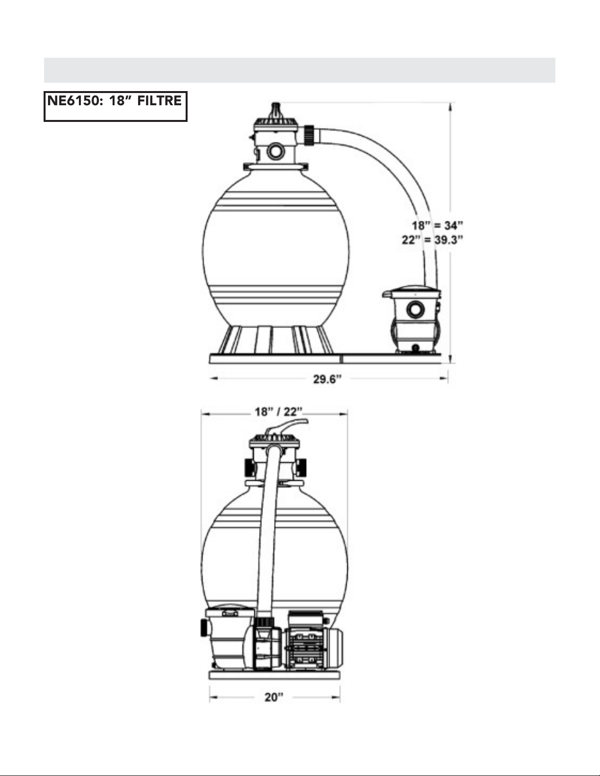
OPERATING YOUR FILTER
• Prime your lter prior to starting up the lter system. DO NOT turn the motor on until the system has been
primed or you can damage your pump.
• Make sure that the water in the pool is up to middle of the skimmer(s) and that there is nothing blocking the
water ow from the return(s) and skimmer(s) (i.e. plug, plate, etc.).
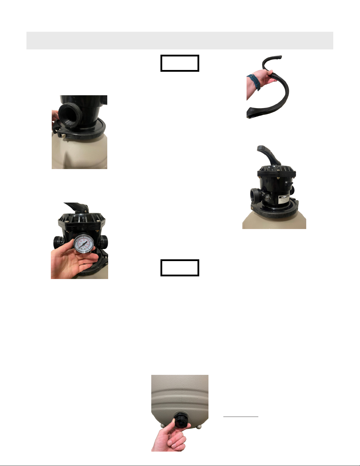
• Push down the selector handle on the valve and turn it to the notch labeled BACKWASH. Let go of the
handle and the valve is now in the correct backwash position. Make sure the backwash hose (sold separately)
is attached to the waste port so water will not spray all over you once the pump is started.
• Remove the lid of the strainer basket on the pump (if applicable) and ll with water. These skimmer and
return lines should be lled with water as well (when the water level is in a proper place in the pool, this will
happen naturally).
• Place the cover back on the basket and plug in/switch on the pump. When the pump starts up, water will
come out through the backwash hose. If the pump is properly primed, the water in the strainer basket will ll
completely and the air pockets will be eliminated.
• Repeat above steps until all air is purged from the system then turn OFF the pump. If this does not get the
air out of the system, double check all connections to make sure they are properly tightened and try again.
• To use the lter, with the pump OFF, push down the selector handle on the valve and turn to the notch
labeled FILTER.
• Connect your pump to power to start the lter operation.
• Note the pressure gauge reading at this time.
• When pressure through the return fades and pressure gauge reads 5 psi above the starting pressure,
you will need to backwash the lter system to remove debris.
• Turn the pump off before moving the selector to the BACKWASH position. Once in this position, turn your
pump back on.
• Water will then come out through the waste port, so position the backwash hose where you would like the
water to run out.
• NEVER backwash for longer than ONE MINUTE at a time! Backwashing longer than one minute will cause
sandblasting of internal components and can lead to damage of the standpipe and/or laterals and will thus
VOID WARRANTY.
• Turn the pump off and move the selector to RINSE position. Rinse will allow water to ow through the
pump to clear out the lines and prevent a puff of sand or debris back into the pool after backwashing .
• Rinse for approximately 15 SECONDS and turn off the pump once again. Move the selector back to the
FILTER position and turn the pump back ON. You are now ltering the pools water.
• The WASTE position does NOT allow water to pass through the lter.
• If there is a point where you would like to take water directly out of the pool, this is the option that allows
you to do so.
• You may also vacuum waste to take serious debris straight out of the pool if/when necessary.
• Remember, this is taking water out of the pool so watch the water level to protect your pump and lter. If
the water drops below the skimmer level you MUST turn the pump off.
• RECIRCULATE selector position allows you to move water in the pool WITHOUT ltering the water. This is
usually used when adding chemicals to the pool, during pool opening, or regular maintenance.
NOTICE
NOTICE Your lter CANNOT be run if the water is not at the proper level in the pool. Running the lter
without water can cause serious damage to your pump and lter.
NEVER move selector handle while pump is on. Pump MUST be switched off to change the
position of the valve. Failure to comply will cause damage to your valve and is not covered by
WARRANTY.

11
TROUBLESHOOTING
LOW WATER FLOW SHORT FILTER CYCLES POOL WATER WON’T
CLEAR UP
1. Check skimmer and pump
strainer baskets for debris.
2. Check for restrictions in intake
and discharge lines.
3. Check for air-leak in intake line
(indicated by bubbles returning to
pool).
4. Backwash lter.
5. Bring sand level in lter down
to 1/2 full.
1. Check for algae in pool and
superchlorinate as required.
2. Be sure chlorine and pH levels
are in proper range. Adjust as
required.
3. Check surface of lter sand for
crusting or cracking. Remove
1” of sand if necessary.
4. Check hair and lint basket on
pump for possible air leak,
lubricate basket lid O-ring as
necessary.
1. Check chlorine, pH, and total
alkalinity levels and adjust as
required.
2. Be sure the ow rate through
the lter is sufcient.
3. Operate the lter for longer
periods of time.
4. Be sure the valve is set on the
“Filter” position.
5. Be sure the sand is between 1/2
and 3/4 full in your tank.
WINTERIZING
• At the end of the season, once you disconect the lter system, remove the valve from the tank. The valve
selector handle should be positioned BETWEEN any of the notches to allow for air ventilation through the
valve to protect it from cracking.
• Remove the drain plug from the bottom of the sand tank to drain water out of the lter tank. Keep this plug off
for the winter to allow any potential water build-up to escape from the tank.
• Empty ALL sand from the lter system and dispose as it is recommended to replace the sand EACH season.
• Rinse out the inside of tank and air dry. You MAY remove the laterals from the standpipe and the standpipe
from the tank.
• Store the tank in an area where it will be protected from harsh elements and keep the valve and tank stored
APART to protect from condensation forming and causing cracks in the tank or valve.
• Run hose water through pump to rinse out and store in a warm, dry place for the winter.

12
This product is warranted to the original purchaser to be free from defects in material or workmanship
for a period of one (1) year from the date of the original retail purchase.
This warranty does not cover defects or damage due to improper installation, alteration, accident, or
any other event beyond the control of the manufacturer. Defects or damage resulting from misuse,
abuse, or negligence will void this warranty. This warranty does not cover scratching or damage that
may result from normal usage.
This product is not intended for institutional or commercial use; the manufacturer does not assume
any liability for such use. Institutional or commercial use will void this warranty.
This warranty is nontransferable and is expressly limited to the repair or replacement of the defective
product. During the warranty period, the manufacturer shall repair or replace defective parts at no
cost to the purchaser. Shipping charges and insurance are not covered and are the responsibility of
the purchaser. Labor charges and related expenses for removal, installation, or replacement of the
product or components are not covered under this warranty.
The manufacturer reserves the right to make substitutions to warranty claims if parts are unavailable
or obsolete.
The manufacturer shall not be liable for loss of use of the product or other consequential or incidental
costs, expenses or damages incurred by the consumer of any other use. The user assumes all risk of
injury resulting from the use of this product.
This warranty is expressly in lieu of all other warranties, expressed or implied, including warranties
of merchantability or tness for use to the extent permitted by Federal or state law. Neither the
manufacturer nor any of its representatives assumes any other liability in connection with this product.
All warranty claims must include the retailer’s information where the product was originally
purchased. A purchase receipt or other proof of date of purchase will be required to process all
warranty claims. The model number and part numbers found within the assembly instructions
will be required when submitting any parts requests or warranty claims.
For further warranty information or inquiries, please call 1 (800) 759-0977
Blue Wave®Products, Inc.
101 N Raddant Drive
Batavia, IL 60510
ONE-YEAR LIMITED WARRANTY

SKU# NE6150 / NE6170
SYSTÈME DE FILTRAGE
AU SABLE SANDMANTM
AVEC POMPE
MANUEL D’INSTRUCTION
*Inclus le filtre pour la
base et le r
é
servoiir
Questions, problèmes, pièces manquantes?
Avant de retourner chez votre détaillant, appelez notre ligne d'assistance aux
consommateurs au 1-800-759-0977, du lundi au vendredi. 8h - 17h (CST) V1: 0122

THANK YOU!
Merci d'avoir acheté ce produit. Nous travaillons 24 heures sur 24 et dans le monde entier pour nous assurer que nos
produits sont de la meilleure qualité possible. Toutefois, dans les rares cas de problèmes lors de l'assemblage ou de
l'utilisation de ce produit, veuillez contacter notre service d'assistance téléphonique aux consommateurs au
800-759-0977 pour obtenir une aide immédiate avant de contacter votre détaillant. Pour plus de détails, veuillez lire
les informations relatives à la garantie à la fin de ces instructions de montage.
Veuillez lire l'intégralité de ce manuel avant de tenter d'assembler, d'utiliser ou d'installer le produit.
CONSERVEZ CE MANUEL D'INSTRUCTIONS.
L'UTILISATION DEPIÈCES DE RECHANGE NON AUTORISÉES ANNULE LA GARANTIE.
ATTENTION INSTALLATEUR ! CE MANUEL CONTIENT DES INFORMATIONS IMPORTANTES SUR
L'INSTALLATION, LE FONCTIONNEMENT ET L'UTILISATION SÛRE DE CE SYSTÈME DE
FILTRATION ET DOIT ÊTRE FOURNI À L'UTILISATEUR FINAL DE CE PRODUIT. LE FAIT DE NE
PAS LIRE ET SUIVRE TOUTES LES INSTRUCTIONS PEUT ENTRAÎNER DES BLESSURES GRAVES.
2
!INFORMATIONS DE SÉCURITÉ

NE6150 & NE6170
A. RÉSERVOIR DE FILTRATION B. BASE C. VALVE 6 VOIES
D. COLLIER DE SERRAGE E. TUYAU VERTICAL F. TUYAUX LATÉRAUX G. JOINT TORIQUE
H. COLLIERS DE SERRAGE I. MANOMÈTRE J. JOINT DROIT (3) K. RUBAN TEFLONTM
L.TUYAU 3’ 1-1/2" M.TUYAU 6’ 1-1/2” N. BOUCHON DE DRAINAGE O. REGARD EN VERRE
LES PIÈCES INDIQUÉES CI-DESSUS SONT CELLES INCLUSES DANS UN SYSTÈME DE
FILTRATION DE 18". CERTAINES PIÈCES PEUVENT ÊTRE DIFFÉRENTES SI VOUS AVEZ
UN SYSTÈME DE FILTRATION DE TAILLE DIFFÉRENTE.
REV. 1/22 3
PIÈCES POUR LE FILTRE À SABLE (PAS À)
AVIS

4
SANDMAN PIÈCES POUR LE FILTRE NE6150 (18”) & NE6170 (22”)
# # De
Pièce
# De
Fabrication
Description Quantit
é
1A NEP2121 AC18601 Base du filtre à sable de 18 pouces 1
1B NEP2122 AC22601 Base du filtre à sable de 22 pouces 1
2 NEP2123 AC72001 Ensemble du bouchon de vidange 1
3 NEP2124 AC18604 Latéral pour filtre à sable de 18 et 22 pouces 1
4A NEP2125 AC18605 Support latéral du tuyau central pour filtre à sable de 18
pouces
1
4B NEP2126 AC22605 Support latéral du tuyau central pour filtre à sable de 22
pouces
1
5A NEP2127 AC18606 Ensemble de libération d'air 18" Filtre à sable 380mm 1
5B NEP2128 AC22606 Ensemble de libération d'air 22" Filtre à sable 490mm 1
6A NEP2129 AC18607 Réservoir de filtration de 18 pouces 1
6B NEP2130 AC22607 Réservoir de filtration de 22 pouces 1
7 NEP2131 AC18608 Bride de fixation 1
8 NEP2132 AC18609 Joint torique pour la valve et le réservoir 1
9 NEP2133 AC08621RP Vanne à 6 voies 1
PIÈCES POUR LE FILTRE À SABLE (SUITE)

SPÉCIFICATIONS DU PRODUIT
5
NE6150: 18” FILTRE
NE6170: 22” FILTRE

INSTRUCTIONS DE MONTAGE POUR LE FILTRE À SABLE
6
Le filtre est partiellement assemblé, mais rien n'a été correctement serré. NE PAS faire
fonctionner le système de filtration sans avoir suivi TOUTES les instructions d'assemblage.
•À l'aide d'un tournevis cruciforme, retirez le collier de fermeture (D) de l'ensemble de la valve. Il suffit de
dévisser complètement un côté car il peut être retiré et réinstallé sans dévisser les deux vis.
•Retirez la valve (C) du réservoir et mettez-la de côté jusqu'à ce qu'on vous indique de la remettre en place.
DIAGRAMME 1
•A l'intérieur du réservoir, vous trouverez le tuyau vertical (E) et
un sac en plastique contenant les latéraux (F).
•Fixez chaque latéral au tuyau vertical en le poussant dans
l'ouverture et en le tournant vers la droite comme indiqué sur le
schéma 1.
•Répétez l'opération pour les SEPT autres latéraux. Voir le
diagramme 2.
NOTE: Vous DEVEZ installer les latéraux sur le tuyau vertical à
l'INTÉRIEUR du réservoir, car le tuyau vertical ne pourra pas être
remis en place par l'ouverture supérieure une fois les latéraux
fixés. Voir le diagramme 1.
DIAGRAMME 2
AVIS
É
TAPE 1

INSTRUCTIONS DE MONTAGE POUR LE FILTRE À SABLE
7
•Le filtre et la pompe doivent être fixés à la base avant de remplir le filtre de sable, car il sera difficile de les manœuvrer
une fois le réservoir rempli.
•Pour fixer votre pompe à la base, déterminez laquelle des deux pompes ci-dessous ressemble le plus à votre pompe et
suivez les instructions correspondantes pour l'installer à sa base.
A. SUPPORT DE STYLE BERCEAU
•Les pompes dont le berceau est situé directement sous le moteur (voir schéma
3) doivent être alignées avec les trous de la base dans la zone surélevée où les
six trous sont rapprochés. Ce type de montage nécessitera l'utilisation de deux
à quatre boulons de montage provenant du paquet de matériel fourni avec la base.
•Alignez la pompe avec la série de trous qui lui conviennent le mieux.
• Et boulonnez en place.
•Passez à l'ÉTAPE 3
B. SUPPORT DE POMPE ENPLASTIQUE
•Les pompes avec des supports de boîtier de pompe en plastique doivent être fixées en alignant les ouvertures avec un
ensemble de trous en forme d'OVALE qui se trouvent vers le centre de la base. Ce type de montage nécessite l'utilisation de
deux boulons de montage provenant du matériel fourni avec la base.
Si vous fixez une pompe Speck SS E90 ou SS E91, utilisez les trous ovales plus grands situés vers l'arrière de la base:
•Vissez le boîtier de la pompe à travers la base, puis serrez.
•Passez à l'ÉTAPE 3.
•Avant de remplir le réservoir de sable, couvrez le tuyau vertical avec un sac en
plastique pour éviter que le sable ne pénètre dans le tuyau vertical. Fixez-le
en place avec un élastique pour qu'il ne tombe pas. Voir le diagramme 4.
•Une fois le sac fixé, placez le tuyau vertical au fond du réservoir de
sable. Assurez-vous que le tuyau est centré dans le réservoir AVANT
de verser le sable, car vous ne pourrez PAS le déplacer une fois que
le sable sera dans le réservoir.
DIAGRAMME 4
Lorsque vous remplissez le réservoir de sable, il ne doit pas être rempli à moins de la moitié et à plus de 3/4.
Un remplissage excessif du réservoir entraînera des dommages permanents à votre système de filtration.
UTILISEZ UNIQUEMENT DU SABLE DE FILTRATION. L'utilisation de sable de jeu causera des problèmes
lors du nettoyage et de la filtration de la piscine.
Si le bouchon de vidange n'est pas aligné avec la troisième flèche OU s'il se soulève de la base,
recommencez les étapes susmentionnées pour fixer correctement votre réservoir à la base.
DIAGRAMME 5
•Le tube en plastique transparent attaché au tuyau de sable est une décharge d'air. Lorsque vous ajoutez le
sable dans le réservoir, essayez de maintenir le tube contre le tuyau vertical. La pièce blanche à l'extrémité
de ce tube doit se trouver AU-DESSUS du niveau du sable lorsque vous avez fini d'ajouter du sable dans le
filtre. Voir le diagramme 5 pour référence.
NE PAS tirer trop fort pour maintenir le tube de décompression, si vous le retirez du fond du tuyau vertical, le
sable pourra alors entrer dans votre piscine par le trou.
ÉTAPE 2
AVIS
AVIS
AVIS
ÉTAPE 3

INSTRUCTIONS DE MONTAGE POUR LE FILTRE ÀSABLE
8
•Ajoutez du sable de filtration (vendu séparément) dans le réservoir du filtre autour du tuyau vertical. La
quantité approximative de sable nécessaire varie en fonction de la taille du filtre que vous avez acheté. Voir
ci-dessous pour obtenir de l'aide.
Réservoir 18” - 110 Lbs.
Réservoir 22” - 220 Lbs.
Réservoir 26” - 360 Lbs.
Retirez le sac en plastique et remplissez le réservoir d'eau jusqu'à ce que le réservoir soit rempli juste en dessous de
l'ouverture du tuyau vertical.
Localisez le joint torique (G) sur la partie inférieure de la valve à 6 voies
(C).
-Lubrifiez-le avec le lubrifiant pour joint torique afin d'assurer une bonne
étanchéité sur le réservoir.
-Poussez le joint torique contre la lèvre de la vanne. Le joint torique DOIT
reposer à plat contre la lèvre pour éviter les fuites au niveau de la valve.
Voir le diagramme 6.
•Nettoyez le sable ou les débris qui se trouvent sur la lèvre supérieure du
filtre et positionnez la valve sur l'ouverture du tuyau vertical.
•- La vanne coulissera SUR le tuyau vertical lorsqu'elle sera correctement
positionnée dans le réservoir (comme indiqué sur le schéma 7). Poussez
fermement pour vous assurer que la valve glisse complètement. La valve
doit maintenant reposer sur le rebord du réservoir et le tuyau vertical,
comme indiqué dans le schéma 8.
DIAGRAMME 7
DIAGRAMME 8
Vous NE POUVEZ PAS tirer le tuyau vertical vers le haut pour fixer la valve. Le fait de tirer vers le haut
peut endommager les latéraux et faire en sorte que du sable soit renvoyé avec le flux d'eau vers la
piscine.
ÉTAPE 3 (SUITE)
DIAGRAMME 6
AVIS
ÉTAPE 4
This manual suits for next models
1
Table of contents
Languages:
Other Blue Wave Water Pump manuals