BlueCard BS-4010M Parts list manual
Land Phone Line Remote Communication Station Usage Manual
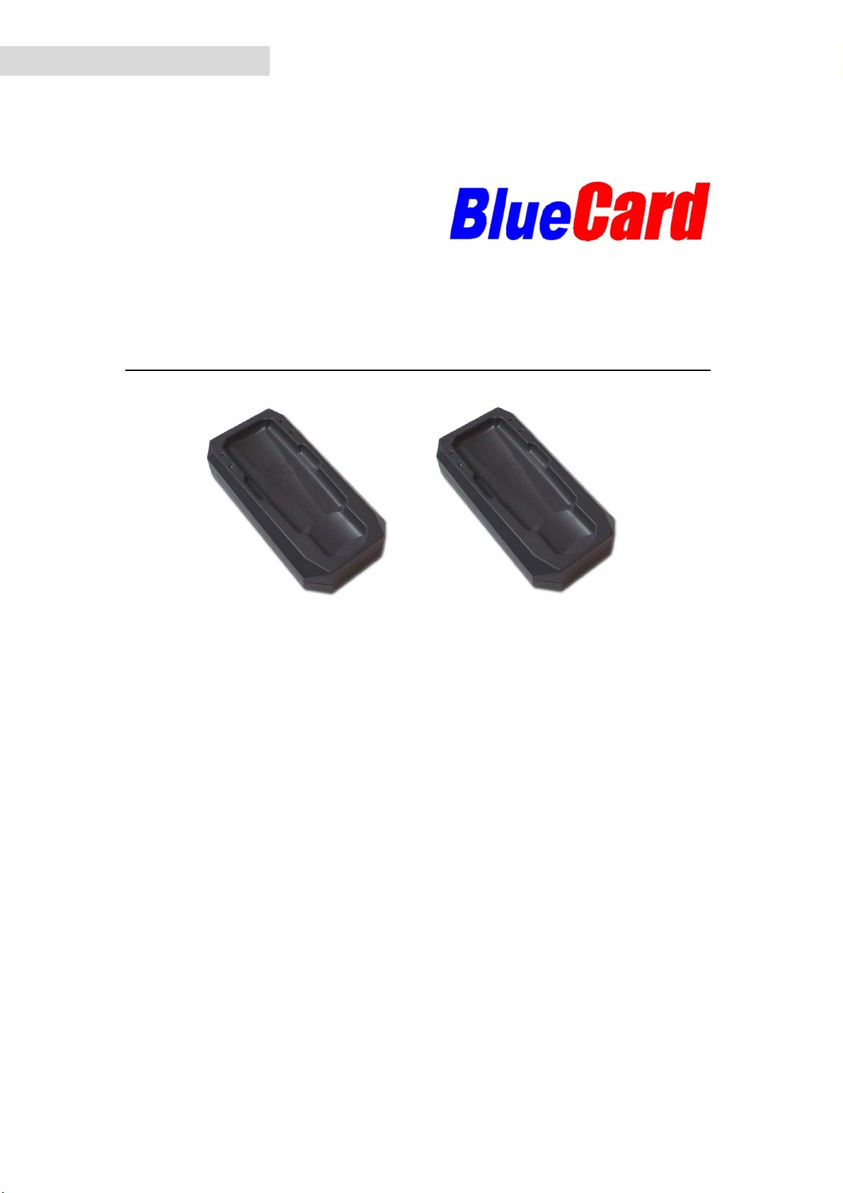
BS-4010M BS-4010
Server Comm. Station Remote Client Comm. Station
Please read this manual carefully, before starting to operate the station.
ENGLISH

1
MainFeatures
The BS-4010 Remote Communication Station (Comm Station) system is able to
collect and remotely upload data from guard tour readers via land-line phone
networks. There are two versions of this product, and both are required for the system
to work:
¾BS-4010 Client: Used at the remote locations to collect data from guard tour
readers and upload data to BS-4010M Server located at the main office.
¾BS-4010M Server: Installed at the main office to receive data from BS-4010
Clients. It serves as a temporary storage place for guard tour data, which can be
later uploaded to the PC via a USB connection.
First-Time Usage
Before download the data from reader, we recommend you to initialize the station to
make sure the station does not have any useless records.

2
TABLE OF CONTENT
DESCRIPTION OFTHE BS-4010M/BS-4010 HARDWARE............................................................3
STATUS LED LIGHTS.................................................................................................................................3
AUDIO SIGNALS ........................................................................................................................................3
POWER SOURCE.........................................................................................................................................4
OPERATING INSTRUCTIONS...........................................................................................................4
INSTALLING THE SOFTWARE.......................................................................................................................4
SETTING UP THE DIAL-UP NUMBER ON THE BS-4010 CLIENT.....................................................................4
COLLECTING DATA FROM GUARD TOUR READERS ......................................................................................6
REMOTE DATA UPLOAD..............................................................................................................................6
LOCAL DATA UPLOAD ................................................................................................................................6
TROUBLESHOOTING.........................................................................................................................7
BS-4010/BS-4010M DATA SHEET.......................................................................................................8
DISCLAIMER........................................................................................................................................8

3
Description of the BS-4010M/BS-4010 hardware
Status LED Lights
(in the descriptions below, “up” indicates the direction on the BS-4010 where the
status LED lights are located):
-Red LED – Upper-Left
∼Flashing: communicating over the mobile phone network.
∼Constant on: the BS-4010 has data that needs to be uploaded.
∼Constant off: the BS-4010 does not have data that needs to be uploaded.
-Green LED – Lower-Left
∼Flashing once per second: the BS-4010 is operating normally.
-Red LED – Upper-Right
∼Constant on: the unit is connected with the remote unit via its modem
module.
∼Constant off: the unit is not connected with the remote unit via its
modem module.
-Blue LED – Lower-Right
∼Flashing once per second: the BS-4010 is operating normally.
∼Flashing quickly: the BS-4010 is communicating with a guard tour
reader.
Audio Signals
There are two types of audio signals: long beep and short beep.
Some of the audio signals below have multiple meanings depending on the situation.
-Short Beep (once)
∼Guard tour reader has been found, but the reader does not contain data
that needs to be uploaded.
∼The local unit has connected successfully with the remote unit via the
phone line.
-Short Beep (twice consecutively)
∼The phone line has not been connected properly.
∼The remote phone number is busy or is not being answered.
∼Guard tour reader has been found, and the reader contains data that needs
to be uploaded.
-Short Beep (three times consecutively)
∼The BS-4010’s memory is full, please upload to the BS-4010m first.
∼Phone dialing has been disabled.
-Long Beep (once)
∼Data transfer from the reader to the BS-4010 has been completed.
-Long Beep (three times consecutively)
∼Data has been completely transferred via the phone line, and the line has
been disconnected.
-Long Beep (once) + Short Beep (three times)
4
∼The BS-4010 is not operable and needs to be initialized by the
manufacturer.
Power Source
-The BS-4010 is able to use multiple types of power supplies:
∼USB connection to the computer.
∼7.5VAC adapter.
∼Car adapter.
-The BS-4010 will turn on automatically after being connected to a power
source. The status LED lights will start flashing at a normal pace if the unit is
operating correctly.
Operating Instructions
Installing the software
¾Install the guard tour system software
¾Install the software provided for BS-4010/BS-4010M, which is named ‘Setup Centre Dial-up
Number’.
The driver for the BS-4010 has been installed when you implemented the guard tour system setup.
Setting up the dial-up number on the BS-4010 Client
¾Please start the ‘Setup Centre Dial-up Number’ program by double clicking on
icon.
There are two ways to store the number into the BS-4010 Client:
-Local Setup
∼Connect the BS-4010 Client to the PC using the USB cable provided.

5
Enter the land-line phone number of BS-4010M Server in the lower blank
space provided. (For example, 58859090 is a land-line number, 841 is an
extension number, ‘,,’ means 2 seconds delay while dialing).
∼Click , it shows the window below.
This indicates the phone No has stored into the BS-4010 successfully.
-Remote Setup
∼Connect the BS-4010M Server to the PC via the USB cable provided.
∼Connect the BS-4010M Server to the local land phone line, and make sure the
BS-4010 Client at the remote location is also connected to remote land phone line.
∼Start the ‘Setup Centre Dial-up Number’ program by double clicking on
icon. And enter the telephone Nos accordingly.
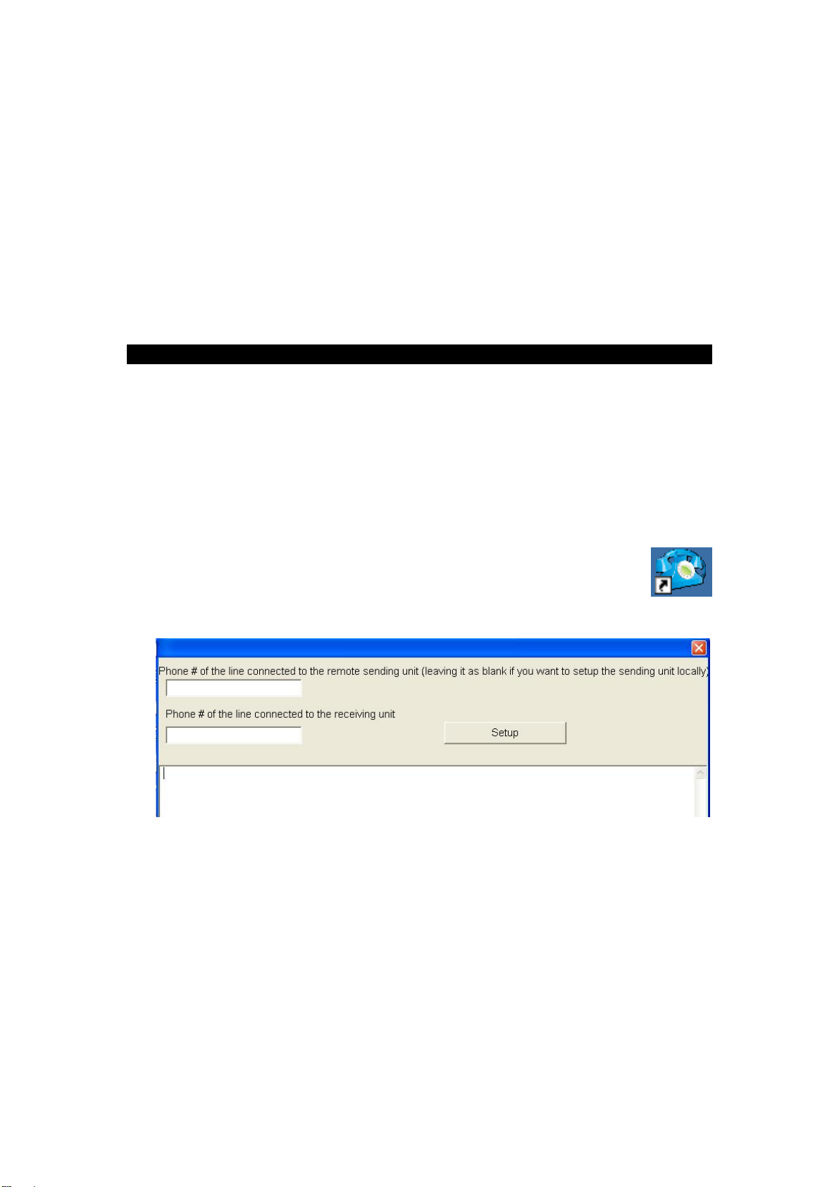
Enter the phone number that the remote BS-4010 Client is connected in the upper
blank space provided. For example, 58859090,,840.
Enter the phone number that the BS-4010M Server is connected in the lower blank
space provided. For example, 58859090,,841.
Click Setup, the above picture indicates the phone No has stored into the BS-4010
successfully.

6
Collecting data from guard tour readers
Both the BS-4010 Client and the BS-4010m Server are able to collect data from guard
tour readers wirelessly. Compatible readers include models BP-2002S, BP-2002F,
BP-2002-W, and BP-2002B-W.
¾Turn on the BS-4010 / BS-4010 M.
¾Set the reader into the indentation on the BS-4010. For reader model BP-2002S,
please place its reading head between the status lights, and set its top flush against
the inside edge of the BS-4010.
¾If there is data that needs to be transferred from the reader to the BS-4010 /
BS-4010M, its blue LED light will start flashing rapidly, indicating that data is
being transferred. When the transfer process is complete, the BS-4010 / BS-4010
M will make one long beep, then one short beep periodically every few seconds,
indicating that the reader connected no longer has any data to upload, and should
be removed. If you have another reader that needs to have its data transferred,
please place it in the unit at this time.
¾If the BS-4010 / BS-4010m makes three short beeps, it means that its memory is
full, and will need to have it uploaded before being able to collect any more data
from readers.
Remote data upload
¾When the BS-4010 Client contains data that needs to be uploaded, if in 30
seconds it does not communicate with a reader or the PC, it will automatically
attempt to dial and connect to the BS-4010 M Server in order to upload its data.
¾If for any reason, the BS-4010 Client fails to upload data upon the first try (for
example, if the BS-4010 M server has not been turned on, or if the dial-up phone
number stored in it is wrong, etc.), the BS-4010 will try again once every 30
seconds for three times. If it fails all three times, the BS-4010 will stop for five
minutes before attempting to dial again.
¾Please go to the next step to upload data to the main software of PC.
Local data upload
¾Both the BS-4010 Client and the BS-4010 M Server are capable of uploading
their stored data to the PC directly.
-Connect the unit to the PC using the provided USB cable.
-Start the patrol management software, and select the appropriate
communication method.
-Open the “connect” screen in the patrol management software, which will
automatically collect data from the BS-4010 / BS-4010 M unit.

7
Troubleshooting
Notabletouploaddatafromtheguardtourreaders.
Check to see if the reader is placed properly on the unit. The reading head of the
reader should be between the status lights of the unit, and its top should be flush
against the inside edge of the unit.
Please note that the BS-4010 / BS-4010 M unit is not able to upload data from guard
tour readers when it is communicating with the PC.
The BS-4010 Client is not able to dial its stored phone number.
Please note that only the BS-4010 Client (not the BS-4010m Server) is able to
automatically dial to upload its stored data. Please make sure that the proper version
of the unit is being used.
If the upper-right red LED flashes once without emitting a beeping sound, it indicates
that no dial-up number has been stored in the unit. Please first store the dial-up
number using the BS-4010 setup program.
If the unit emits two short beeps, it indicates that either it did not detect a working
phone line, or that the dialed number is busy.
Thepatrolmanagementsoftwareisnotabletofindtheunit.
Please check the condition of the hardware installation by going into the Windows
Device Manager.
In all conditions, please first check to see if the BS-4010 / BS-4010 M unit is
operating properly, by making sure that its LED lights are flashing at the appropriate
intervals. If not, please disconnect then reconnect its power source in order to
reinitialize the unit.
Please contact with the technology support if you can not solve the problem by
using above solutions.

8
BS-4010/BS-4010M Data Sheet
DISCLAIMER
The information in this documentation is subjective to change notice and does not
represent a commitment on the part of Bluecard Software Technology Co., Ltd. No
part of the this manual may be reproduced or transmitted in any form or by any means,
electronic or mechanical, including photocopying, recording, or information storage
and retrieval systems, for any purpose other than the purchaser’s personal use, without
the written permission of Bluecard Software Technology Co., Ltd.
All trademarks mentioned in the document, belong to their respective owners.
Bluecard Software Technology Co., Ltd.
Size: 159x79x33mm
Color: Dark Grey
Connection With Readers: RFID Wireless Connection
Connection With PC: USB
Memory Flash Memory
Storage Capacity 49713 records
Card reading format EMID RFID
Operating temperature -20°C to 70°C
Operating humidity 0 to 95%
This manual suits for next models
1
Table of contents
Other BlueCard Conference System manuals


