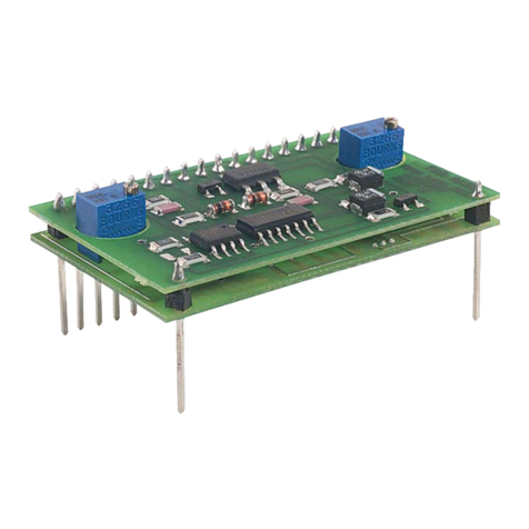
THORLABS LDM9T User manual
Other THORLABS Controllers manuals
THORLABS
THORLABS TSC001 User manual
THORLABS
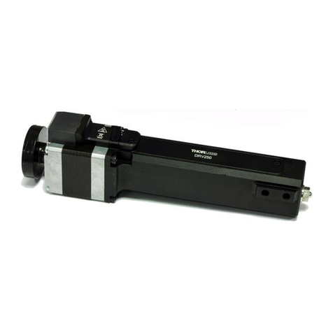
THORLABS DRV225 User manual
THORLABS
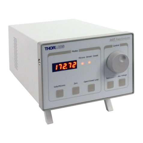
THORLABS BPC301 User manual
THORLABS
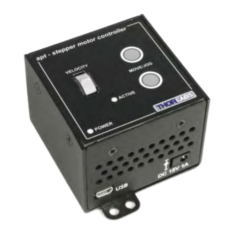
THORLABS TST101 User manual
THORLABS
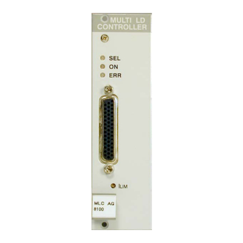
THORLABS MLC8 Series User manual
THORLABS
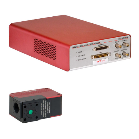
THORLABS LSK-GR08 User manual
THORLABS
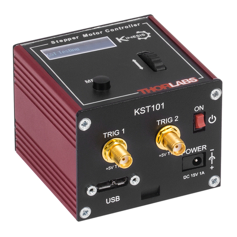
THORLABS KST101 User manual
THORLABS
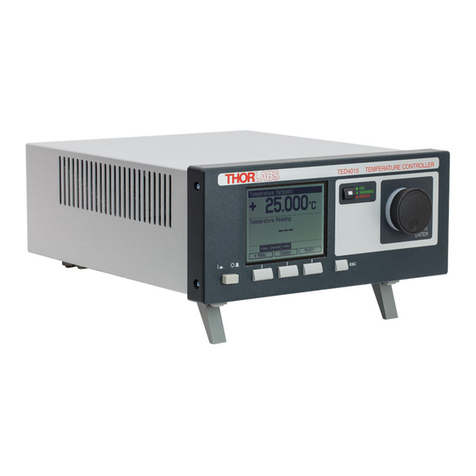
THORLABS LDC40 Series User manual
THORLABS
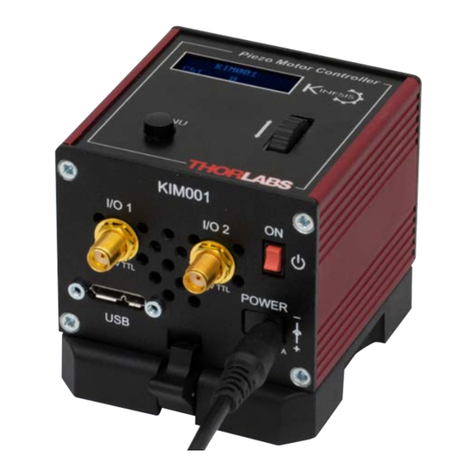
THORLABS KIM001 User manual
THORLABS
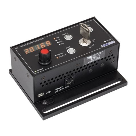
THORLABS TLD001 User manual
THORLABS
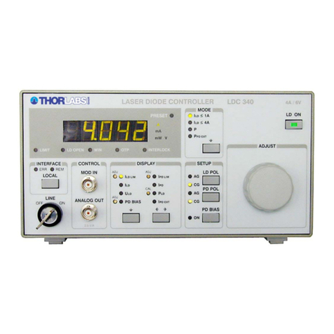
THORLABS LDC340 User manual
THORLABS
THORLABS SHB1 User manual
THORLABS
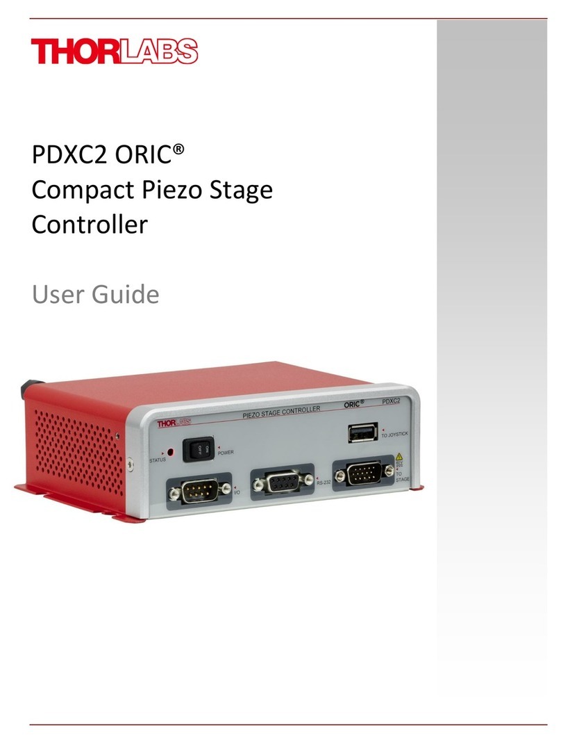
THORLABS ORIC PDXC2 User manual
THORLABS
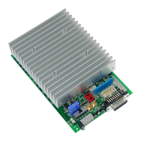
THORLABS ITC1 Series User manual
THORLABS
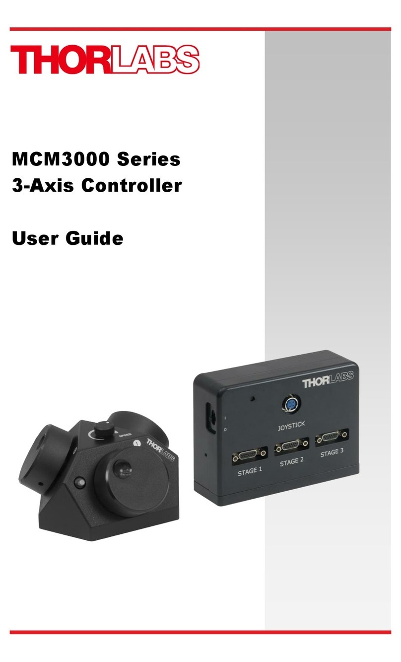
THORLABS MCM3000 Series User manual
THORLABS
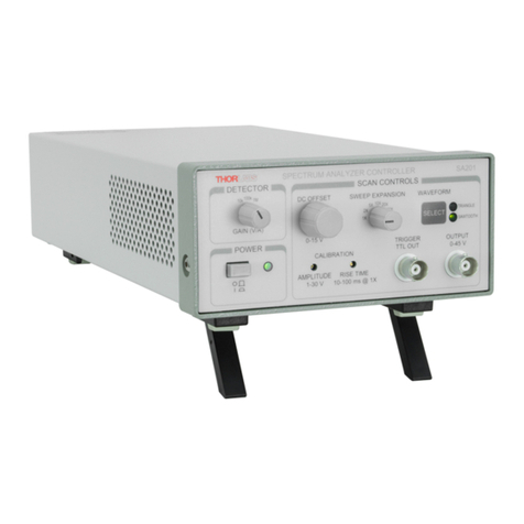
THORLABS SA201-EC User manual
THORLABS
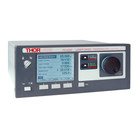
THORLABS ITC4000 Series User manual
THORLABS
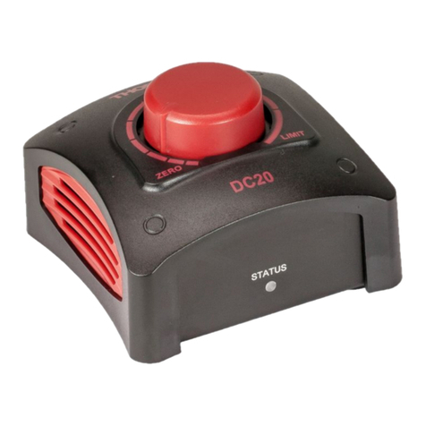
THORLABS SOLIS DC20 User manual
THORLABS
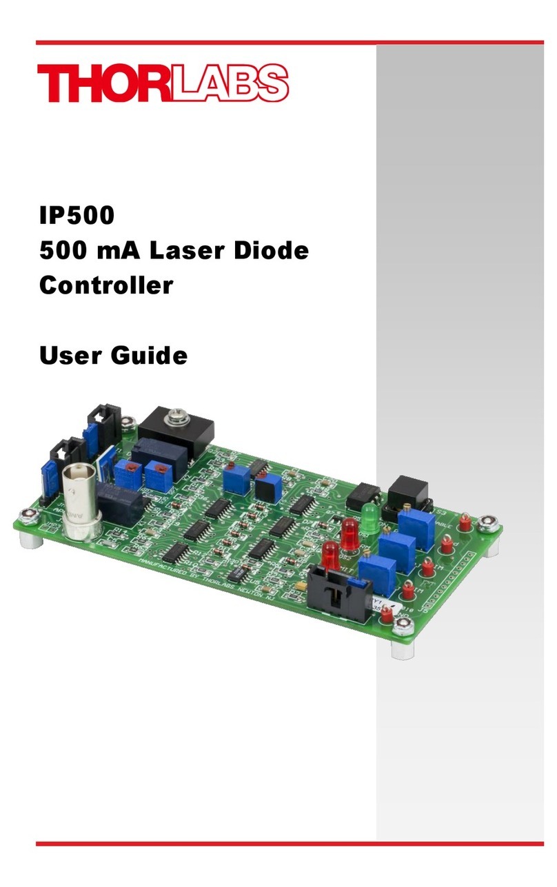
THORLABS IP500 User manual
THORLABS
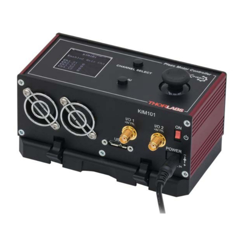
THORLABS KIM101 User manual
Popular Controllers manuals by other brands

Digiplex
Digiplex DGP-848 Programming guide

YASKAWA
YASKAWA SGM series user manual

Sinope
Sinope Calypso RM3500ZB installation guide

Isimet
Isimet DLA Series Style 2 Installation, Operations, Start-up and Maintenance Instructions

LSIS
LSIS sv-ip5a user manual

Airflow
Airflow Uno hab Installation and operating instructions
