Blueprint PNGCP18003 Owner's manual

1.800.338.7337 / www.soundoffsignal.com
PNGCP1800(x) 0419
CONTROL PANEL
PNGCP18003
PNGCP18004
PROGRAMMING MANUAL
NOTE:
A. For All programming modes: Momentarily depress Radio
Rebroadcast push-button to exit.
B. To hear samples of all the tones available go to www.
soundoffsignal.com website.
INPUT SETTINGS:
1. Press and Hold Auxiliary Button 1 and 3 until slide switch #3 LED
ashes.
1. Park Kill Polarity Mode: Determines what voltage level will
activate park kill functions.
ON = activated when +V is applied to Park
Kill input wire.
OFF = activated when Ground is applied to
Park Kill input wire.
5. Horn Ring Timeout: (Alternate Horn Ring control must be
disabled for function to have any effect). When vehicle
horn is pressed and tone changes, determines how tone
will change back to pre-vehicle horn press tone. This
feature can be applied to scroll and latch modes. (See
Horn Ring Table).
ON = siren tone will revert back to
pre-vehicle horn press tone after 8
seconds
OFF = siren tone will not revert back
to pre-vehicle horn press tone
6. Park Kill Latch: When Park Kill input is triggered, determines
how siren tone proceeds once park kill input is no longer
active. (Disables Auxiliary Input)
ON = Tone remains disabled until operator
selects other tone
OFF = Tone resumes once Park Kill input
is no longer active
7. Horn Ring Scroll: Determines how siren tone will change each
time the operator presses the vehicle horn. (See Horn
Ring Table).
ON = Tone will advance through tones
programmed on Wail, Yelp, and Tone push-
buttons each time vehicle horn is pressed.
*Only if a tone is already active.
OFF =Tone will toggle between control
panel tone and next priority tone. If tone
can not transfer to higher priority tone,
Airhorn will momentarily play
8. Auxiliary Input: Determines which siren tone will be activated
when auxiliary input is activated.
ON = Air Horn tone
OFF = Tone which is programmed on
Wail push-button
GRAYED AREAS DENOTE FACTORY DEFAULTS
2. Horn Ring Polarity Mode: Determines what voltage level will
activate Horn Ring functions.
ON = activated when +V is
applied to Horn Ring input wire
OFF = activated when Ground is
applied to Horn Ring input wire
3. Tone Select*: Determines if the Tone Select activation will
allow a siren tone to be produced.
ON = Tone Push-button Enabled
OFF = Tone Push-button Disabled
4. Level 3 tone activation*: Determines when the siren tone
push-buttons on control panel are enabled.
ON = Tone push-buttons always
enabled
OFF = Tone push-buttons only enabled
when slide switch is in position #3.
C. The Push Button version (shown above) works the same as
the rotary switch version with 2 exceptions:
1. Gun Release Interlock (Button:STBY; Rotary: RR)
2: Rotary Switch version only - Parasidic Current- To place
unit in lowest possible current consumption mode (with
ignition off), rotary switch must be in “off” position.
* Siren Control Select for push button or rotary switch versions
program the same.
PUSH BUTTON (SHOWN BELOW) SIMILAR TO ROTARY SWITCH
(NOT SHOWN)
LEGEND:
ON - GREEN
OFF - BACKLIGHT ON - RED
BACKLIGHT OFF - OFF
NOT APPLICABLE
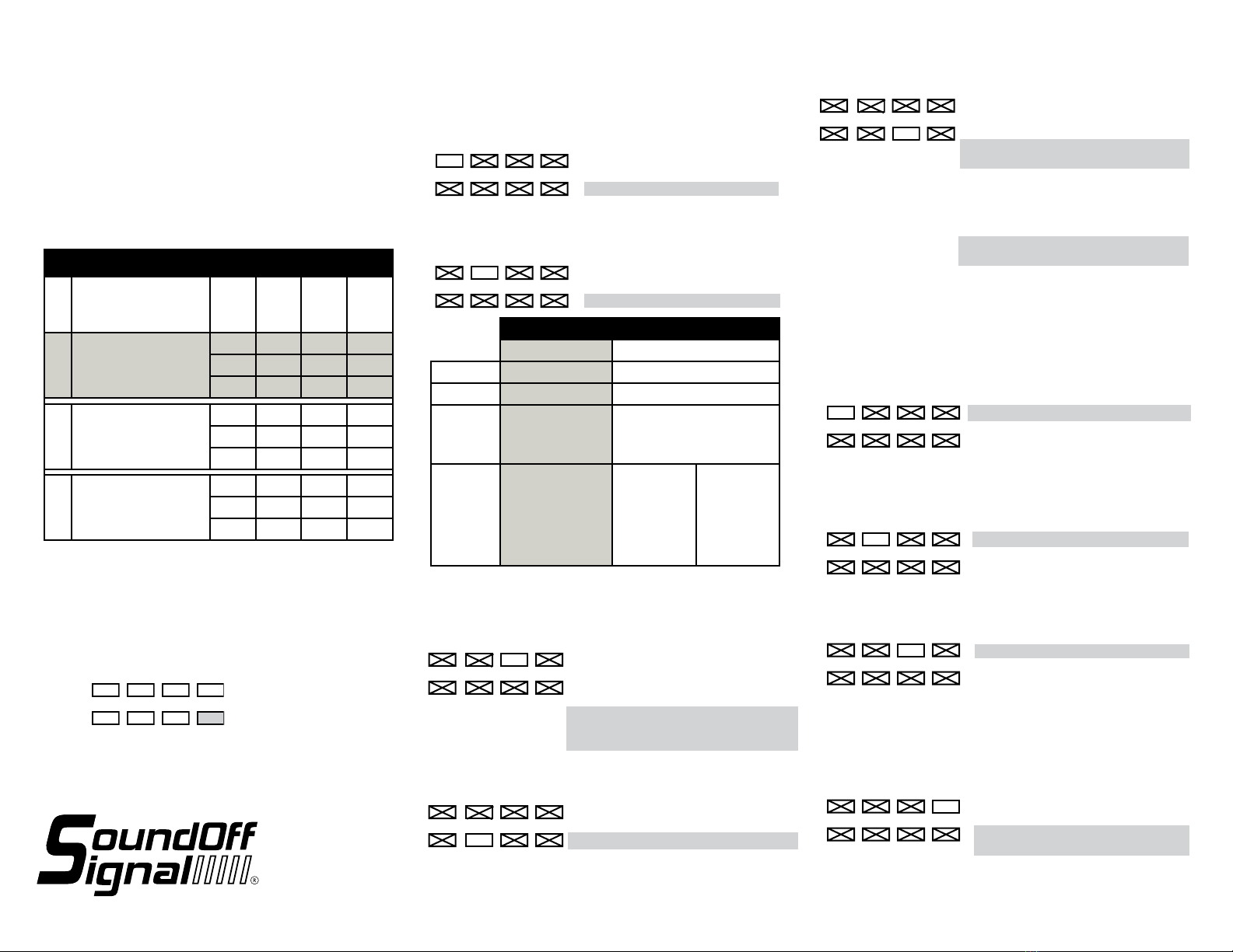
Horn Ring Conguration
Settings
*Siren Tone Must Be ON*
Hornring
Scroll
Hornring
Latch (see
#4 in OTHER
MODES on
pg. 7.)
Hornring
Timeout Output Behavior
Modes
Scroll
ON X
OFF
Pressing the horn in this mode
will advance to and latch the next
priority tone. (W->Y->T->W...).
The tone is cancelled by pressing
the control panel stanyby or siren
tone buttons.
ON
Same as above with the added
feature of the tone being cancelled 8
seconds after the horn is released.
Latch/Toggle
OFF ON
OFF
Pressing the horn in this mode will
toggle between the current control
panel tone and the next priority
tone. If the tone can not transfer to
a higher priority tone, the airhorn will
sound while the horn is pressed.
ON
Same as above with the added
feature of the tone being cancelled 8
seconds after the horn is released.
Momentary
OFF OFF
OFF
Pressing the horn in this mode will
momentarily play the next priority
tone while the horn is held.
ON
Same as above with the added
feature of the tone being cancelled 8
seconds after the horn is released.
(Single Output)
Slide Switch
LEDs
Arrow Control
Display
Slide (Level) Switch
(Siren & Multiple Outlets)
S1 Primary Speaker
S2 Secondary Speaker
Diagnostic
Siren Control Select *
AUXILLARY BUTTON #s
1 2 3 4
5 6 7 8
Siren Control
Momentary
Pg. 1
►
►
1.800.338.7337 / www.soundoffsignal.com
PNGCP1800(x) 0419
SLIDE SWITCH SETTINGS:
1. Press and hold Auxiliary Push-Button “1” and “4” until slide
switch #2 indicator LED ashes.
2. Press Auxiliary Push-Button “1”, “2” or “3” depending on
which conguration for the slide switch is required.
HIGH
LOW 2
65
3
7
4
Setting PA Volume:
1. Press and Hold Auxiliary Push-Button “1” and “2” until slide switch
#2 and #3 indicator LED ashes.
2. Depress and hold PA switch on microphone and press Push-Button
“1”-“8” depending on volume required. When correct
volume is determined, press Radio Rebroadcast and the
volume setting will be permanently stored.
ALTERNATE MODES:
1. Press and Hold Auxiliary Push-Button “2” and “6” until Slide
Switch indicator #1 and #2 LED ashes.
1. Alternate Horn Ring control: Custom operation of vehicle
horn when pressed. Refer to gure below for details.
ON = Enabled
OFF = Disabled
2. Alternate Horn Ring control option: (Alternate Horn Ring
Control must be enabled). Custom operation of vehicle
horn when pressed. Refer to gure below for details.
ON = Option 2
OFF = Option 1
ALTERNATE HORN RING CONTROL
OPTION 1 OPTION 2
STANDBY OEM HORN OEM HORN
LEVEL 1 OEM HORN OEM HORN
LEVEL 2 Air Horn or Wail
Button Tone while
Pressed *
Tap to Turn On Warning Tone,
Tap again to Change Warning
Tone. Press and Hold for Air
Horn Tone
LEVEL 3 Tap to turn ON
Warning Tone, Tap
again to change
Warning Tone. Press
and Hold for Air Horn
Tone
TONE
SWITCH OFF:
Air Horn Tone
or Wail Button
Tone while
Pressed *
TONE
SWITCH ON:
Tap to change
Warning Tone,
Press and Hold
for Air Horn
Tone
BACKLIGHT INTENSITY:
While pressing RADIO REBROADCAST BUTTON,
press Auxiliary Push-Button “1”-”8” to adjust backlight intensity.
“1” = Lowest intensity, “8” = Highest intensity.
Backlight must be enabled by the Gray wire on CN6.
3. GUN LOCK SECURITY:
ON = Operator must press Standby button
within 1 second after pressing 8
second time delay button to active
switch
OFF = 8 second time delay switch is
activated immediately when
pressed
6.DISABLE RELAY ERROR FOR AUX 7 & 8:
ON = Disable fault detect indication for
Aux relays 7& 8.
OFF = Fault detect normal.
SLIDE SWITCH SETTINGS
MODE
RELAY
OUTPUT
#1
RELAY
OUTPUT
#2
RELAY
OUTPUT
#3
SLIDE
SWITCH
POSITION
1AUXILIARY PUSH-BUTTON 1
IS SELECTED
1
2
3
2AUXILIARY PUSH-BUTTON 2
IS SELECTED
1
2
3
3AUXILIARY PUSH-BUTTON 3
IS SELECTED
1
2
3
CONTROL PANEL
PNGCP18003
PNGCP18004
PROGRAMMING MANUAL
* Set in “Other Modes” 6. Horn Ring Standby Tone
Pg. 2
7. Slide Switch Enabled Without Ignition: After ignition
is turned off, device will stay on in lower power mode and allow
(ONLY) the slider to operate.
ON = With ignition off, slider relays will
still turn on if slider is in position 1,
2, or 3.
OFF =Device turns off normally, sliders
will not work when off.
8. Invert Backlight Color: Swap the background and active
colors of buttons.
ON = Backlight color is green, active is
red.
OFF = Backlight color is red, active is
green.
OTHER MODES:
Press and Hold Auxiliary Button “1” and “5” until slide switch #1
and #3 indicator LED ashes.
1. Horn Ring Activation: Determines when pressing the Vehicle
Horn will activate siren tone
ON = Enabled whenever siren is ON
OFF = Enabled only when slide switch
is in level position 3
2. Buzzer: Audible tone from control panel whenever operator
presses push-button or changes position of slide/rotary
switch
ON = Buzzer enabled
OFF = Buzzer disabled
3. Speakers Diag LED disable: Disabling Diagnostic LED does
not turn off secondary speaker channel
ON enable Diagnostic LED (200W)
OFF disable Diagnostic LED (100W)
4. Horn Ring Latch Mode: (Alternate Horn Ring Control Must
be Disabled) Activates the siren tone per scroll mode off
settings when operator momentarily presses on Vehicle
Horn. *Wail Only. Only works when tone is already
active. (See Horn Ring Table).
ON = Horn ring Toggle Switch Mode
OFF = Horn ring Momentary Switch
Mode

1.800.338.7337 / www.soundoffsignal.com
PNGCP1800(x) 0419
CONTROL PANEL
PNGCP18003
PNGCP18004
PROGRAMMING MANUAL
PROGRAMMING MODES
AUXILIARY SWITCH SETTINGS:
Refer to Siren Amplier Diagnostic Indicator Chart below for Button and LED
locations and terminology
1. Press and Hold Auxiliary Button #1 and #8 until slide switch #1 LED
ashes.
2. Press the button which setting is going to be viewed/changed 1 time.
3. Monitor the 5 LED’s for the arrow controller to determine setting
- *Arrow Controller (Left, Right, Center, OFF), Dual Output; 1 & 9
- Alternate Action Switch (Press ON / Press OFF)
- Momentary Action Switch (ON only when depressed)
- 8 Second ON Time (ON for 8 seconds when depressed)
- Level 1 Disable (Turns OFF Level 1 Output)
- Level 2 Disable (Turns OFF Level 2 Output)
- Left Arrow, Single Output
- Right Arrow, Single Output
- Center Arrow, Single Output
- Warning Bar Output
4. Press and release button until desired mode is selected.
5. Continue steps 2-3 for any other buttons that need to be programmed.
*Can only be programmed to one button
and will disable Left, Right and Center
Arrow Single Outputs if they are used.
Denotes Factory Default Setting
Default Settings:
Button #1: Arrow Controller
Button #2-7: Alternate Action Switch
Button #8: 8 Second ON Time
Slide switch mapping programming:
Allows the operator to have the siren automatically turn on auxiliary
push-buttons or tones based on the position of the slide switch.
If an auxiliary or tone push-button is programmed to turn ON when
the slide switch position is selected, the auxiliary push-button
will turn OFF when the programmed slide switch position is no
longer selected.
The operator can override the automatic activation of the auxiliary
push-button by momentarily pressing the auxiliary push-button.
To program:
1. Press auxiliary push-buttons ‘4’ and ‘5’ for until Radio
Rebroadcast indicator LED ashes.
2. Move slide switch to desired position.
3. Press auxiliary push-buttons ‘1’ – ‘8’ and or Siren Control Select
as required.
4. Repeat steps 2 and 3 for other slide switch positions as
required.
5. Place appropriate button legend over activity indicator for each
programmed button.
LED ON
(GREEN)
Auxiliary push-button or Siren Control Select
will automatically turn ON when level switch
position is activated.
LED OFF
(RED OR OFF)
Auxiliary push-button or Siren Control Select
will NOT automatically turn ON when level
switch position is activated.
DIAG S1 S2 CONDITION
FLASHING OFF ON UNDER-VOLTAGE
FLASHING ON OFF OVER-VOLTAGE
FLASHING FLASHING - COMM FAULT - RELAY
FLASHING - FLASHING COMM FAULT - AMP
FLASHING FLASHING FLASHING COMM FAULT -RELAY AND AMP
- - - -
*OFF ON - SPKR 1 IS ACTIVE
*OFF - ON SPKR 2 IS ACTIVE
*OFF OFF - SPKR 1 IS NOT-FUNCTIONING
*OFF - OFF SPKR 2 IS NOT-FUNCTIONING
SIREN AMPLIFIER DIAGNOSTIC
INDICATORS: * SIREN AUDIO BUTTON ACTIVATED
(EXCEPT RADIO REBROADCAST)
Pg. 3
6.Horn Ring Standby Tone: (Alternate Horn Ring Control Must be
Disabled) Determines which tone to output when siren is in
standby and vehicle horn is pressed
ON = Air Horn Tone
OFF = Manual Button Tone
7. 8 Second Buzzer Alert: Provides audible beep every 8 seconds
whenever any auxiliary switches are ON or level 1,2, or 3 is
active.
ON = Enabled
OFF = Disabled
8. Air Horn Button Output Channels
ON = In standby mode, Horn tone is
output on Spkr A & B. When
Warning Tone is Active,
Warning Tone continues on Spkr
A & Air Horn Button Tone is
output on Spkr B.
OFF = Horn Button Tone always
produced on Spkr A & B.
OTHER MODES CONTINUED:
5. Power Down: Determines siren operation after ignition wire input
has no voltage
ON = Timed Power Down: Siren will
power down 10 min. after last
activity.
OFF = Immediate Power Down: Siren
will power down immediately
after ignition is turned off.
►
►

1.800.338.7337 / www.soundoffsignal.com
PNGCP1800(x) 0419
CONTROL PANEL
PNGCP18003
PNGCP18004
PROGRAMMING MANUAL
PARK KILL SETTINGS: Enables auxiliary and slider outputs
to be disabled when Park Kill input is active. Auxiliary outputs
can be turned back on by pushing the buttons again; slider
outputs are disabled as long as the Park Kill input is active.
1. Push and hold Auxiliary Push-Buttons 2 & 3 until arrow
indicator LEDs ash.
2. Press Push-Buttons 1-8 to toggle whether that auxiliary output
will turn off when Park Kill input becomes active. LED on
means output will turn off.
3. Move slider switch to position 1, 2 or 3. Press the Manual
button to toggle whether that output relay is disabled while
Park Kill is active. LED on means that relay will be off. E.g: if
LED for slide position 3 is on, Slide Switch Level 3 Output will
be disabled; Level 1 & 2 outputs can still be on when slider is
in position 3.
4. Repeat step 3 as needed.
5. Press the Radio Rebroadcast button to exit programming
mode.
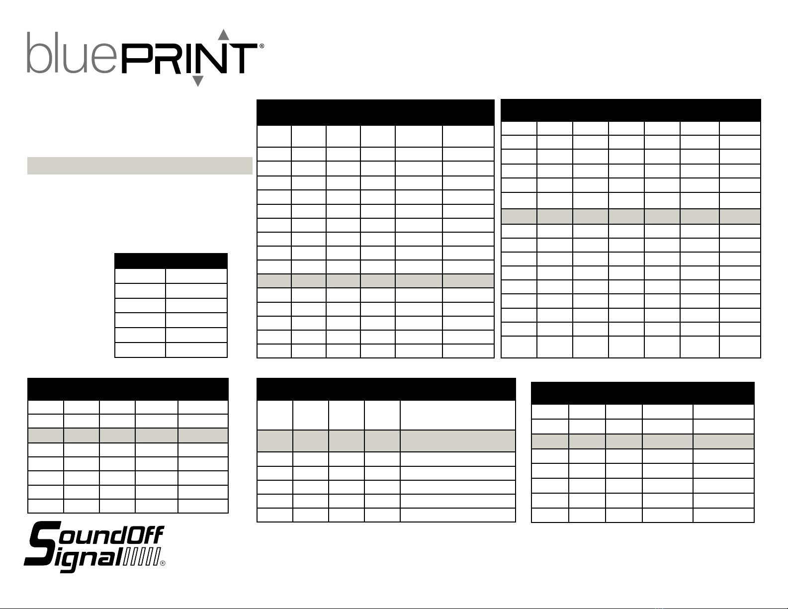
TONE PROGRAMMING:
1. Press and hold “buttons” “2” and “7” for 2 seconds until Slide
switch LEDs 1,2, and 3 ash
2. Press Control Selected to be programmed (Wail, Yelp, Tone,
Manual, or Horn). Auxillary button 1 = HORN, button 2 =
MANUAL
3. Auxillary buttons 5-8 will determine which tone is to be played
when the user presses the button.
4. Repeat steps 2 and 3 for each tone button
MANUAL BUTTON TONE DURATION
MOMENTARY: When played solo
LATCHED: When played over other tones.
Pg. 4
NOTICE:
Installers and users must comply with all applicable federal, state and local laws regarding use and installation of warning devices.
Improper use or installation may void warranty coverage.
To review our Limited Warranty Statement & Return Policy for this or any SoundOff Signal product, visit our website at www.soundoffsignal.com/tech-services/returns/.
If you have questions regarding this product, contact Technical Services, Monday - Friday, 8 a.m. to 5 p.m. or after hours 5 p.m. to 8 p.m. ET at 1.800.338.7337 (press #4).
SUPERIOR CUSTOMER RELATIONSHIPS. SMARTLY DESIGNED LIGHTING & ELECTRONIC SOLUTIONS.
►
►
1.800.338.7337 / www.soundoffsignal.com
PNGCP1800(x) 0419
CONTROL PANEL
PNGCP18003
PNGCP18004
PROGRAMMING MANUAL
BUTTON
#6
BUTTON
#7
BUTTON
#8
SPKR A SPKR B
OFF OFF OFF WAIL 1 WAIL 1
OFF OFF ON WAIL 2 WAIL 2
OFF ON OFF WAIL 1 WAIL 2
OFF ON ON WAIL 1 YELP 1
ON OFF OFF WAIL 1 ALERT A
ON OFF ON WAIL 1 HiLo
ON ON OFF WAIL 2 SUPER HiLo
ON ON ON WAIL 2 PIERCER
WAIL BUTTON
BUTTON
#6
BUTTON
#7
BUTTON
#8
SPKR A SPKR B
OFF OFF OFF YELP 1 YELP 1
OFF OFF ON YELP 2 YELP 2
OFF ON OFF YELP 1 YELP 2
OFF ON ON YELP 1 WAIL 1
ON OFF OFF YELP 1 PIERCER
ON OFF ON YELP 1 HiLo
ON ON OFF YELP 2 SUPER HiLo
ON ON ON YELP 2 PIERCER
YELP BUTTON
BUTTON
#5
BUTTON
#6
BUTTON
#7
BUTTON
#8
SPKR A SPKR B
OFF OFF OFF OFF TONE
SCROLL*
TONE
SCROLL*
OFF OFF OFF ON PIERCER PIERCER
OFF OFF ON OFF HiLo HiLo
OFF OFF ON ON SUPER HiLo SUPER HiLo
OFF ON OFF OFF ALERT A ALERT A
OFF ON OFF ON ALERT A HiLo
OFF ON ON OFF ALERT A SUPER HiLo
OFF ON ON ON HiLo SUPER HiLo
ON OFF OFF OFF HiLo PIERCER
ON OFF OFF ON ALERT A ALERT B
ON OFF ON OFF PIERCER YELP 1
ON OFF ON ON PIERCER WAIL 1
ON ON OFF OFF SUPER HiLo PIERCER
ON ON OFF ON WAIL 1 WAIL 2
ON ON ON OFF YELP 1 YELP 2
ON ON ON ON WAIL 1 YELP 1
TONE BUTTON
BUTTON
#1
BUTTON
#5
BUTTON
#6
BUTTON
#7
BUTTON
#8
SPKR A SPKR B
ON OFF OFF OFF OFF HORN 1 HORN 1
ON OFF OFF OFF ON HORN 2 HORN 2
ON OFF OFF ON OFF HORN 3 HORN 3
ON OFF OFF ON ON HORN 4 HORN 4
ON OFF ON OFF OFF HORN 1 HORN 2
ON OFF ON OFF ON HORN 1 HORN 3
ON OFF ON ON OFF HORN 1 HORN 4
ON OFF ON ON ON HORN 2 HORN 3
ON ON OFF OFF OFF HORN 2 HORN 4
ON ON OFF OFF ON HORN 3 HORN 4
ON ON OFF ON OFF HORN 1 WAIL 1
ON ON OFF ON ON HORN 1 YELP 1
ON ON ON OFF OFF HORN 1 PIERCER
ON ON ON OFF ON HORN 2 YELP 1
ON ON ON ON OFF HORN 3 YELP 1
ON ON ON ON ON HORN 4 SUPER
HiLo
HORN BUTTON
BUTTON
#2
BUTTON
#6
BUTTON
#7
BUTTON
#8
SPKR A/B
ON OFF OFF OFF WAIL 1
FREQUENCY DECREASE WHEN
RELEASED
ON OFF OFF ON WAIL 1
IMMEDIATE OFF WHEN RELEASED
ON OFF ON OFF YELP 1
ON OFF ON ON PIERCER
ON ON OFF OFF ALERT A
ON ON OFF ON HiLo
ON ON ON OFF SUPER HiLo
MANUAL BUTTON (SOLO PLAY ONLY)
Denotes Factory Default Setting
SPKR A SPKR B
WAIL 1 WAIL 2
WAIL 2 YELP 1
YELP 1 YELP 2
YELP 2 PIERCER
PIERCER ALERT A
ALERT A WAIL 1
*TONE SCROLL
MANUAL BUTTON TONE DURATION
MOMENTARY: When played solo
LATCHED: When played over other tones.
Pg. 5
►
►
This manual suits for next models
1
Table of contents
Popular Control Panel manuals by other brands

BLAUBERG Ventilatoren
BLAUBERG Ventilatoren S25 user manual

Eaton
Eaton Greengate LiteKeeper 8 installation instructions

Digital Monitoring Products
Digital Monitoring Products XR2500F user guide

HST
HST Addressable fire alarm MN-300 operating instructions

Extron electronics
Extron electronics ACP 105 D Setup guide

Vacon
Vacon 7-segment Control Panel manual


Garmin
Garmin GPSMAP 8X10 owner's manual

Crow
Crow Runner Series Installation and configuration guide

Chamberlain
Chamberlain LiftMaster Professional CB124 instructions

Haes
Haes FCPTEC-HS-4200 Installation & commissioning manual

Festo
Festo CP-E16-M8 manual

Siemens
Siemens SPC5000 Installation & configuration manual