BlueRange UNL12 User manual
USER MANUAL
SOLAR POWERED AUTO-DARKENING WELDING HELMET
MODEL NO: UNL12
PART NO: BR9008000
IMPORTANT NOTICE:
Keep these instructions safe for future reference.
Read instructions carefully, follow the safe working practices outlined and heed the
warnings. Failure to do so may lead to personal injury or damage the product.
USER MANUAL
SOLAR POWERED AUTO-DARKENING
WELDING HELMET
NOTE – This helmet is not suitable for Grinding.
MODEL NO: UNL12
PART NO: BR9008000

Page 2
1) Introduction
Auto-darkening welding helmets are designed to protect the eyes and face from sparks, splatter, and harmful
radiation under normal welding conditions. The auto-darkening lter (ADF) automatically changes from a
light to dark state when an arc is struck and returns to the light state when the welding arc disappears.
The Auto-darkening welding helmet comes ready to use. The only thing you need to do before welding is to
adjust the position of the headband and select the correct shade number for your application.
WARNING PLEASE READ THIS MANUAL CAREFULLY BEFORE USING
2) Technical Specications
Great for MMA, MIG, MAG and TIG.
!
Cartridge Size 110mm × 90mm × 9mm
Active Viewing Area 92mm × 42mm
Light Shade DIN4
Dark Shade DIN9-13
Shade Control Variable adjusted by external knob
Power On/O Auto
Switching Time 1/25000S
Sensitity Control Variable adjusted by external knob
Delay Time 0.1S~1.0S Variable adjusted by external knob
Power Supply Solar cells and replaceable CR2032 lithium battery
Operating Temperature -5°C+55°C
Store Temperature -20°C+70°C
Arc Sensors 4
UV/IR Protection DIN16
Grind Yes
True Colour Yes
Replace Battery Yes
AC/DC TIG >5amps
Page 3
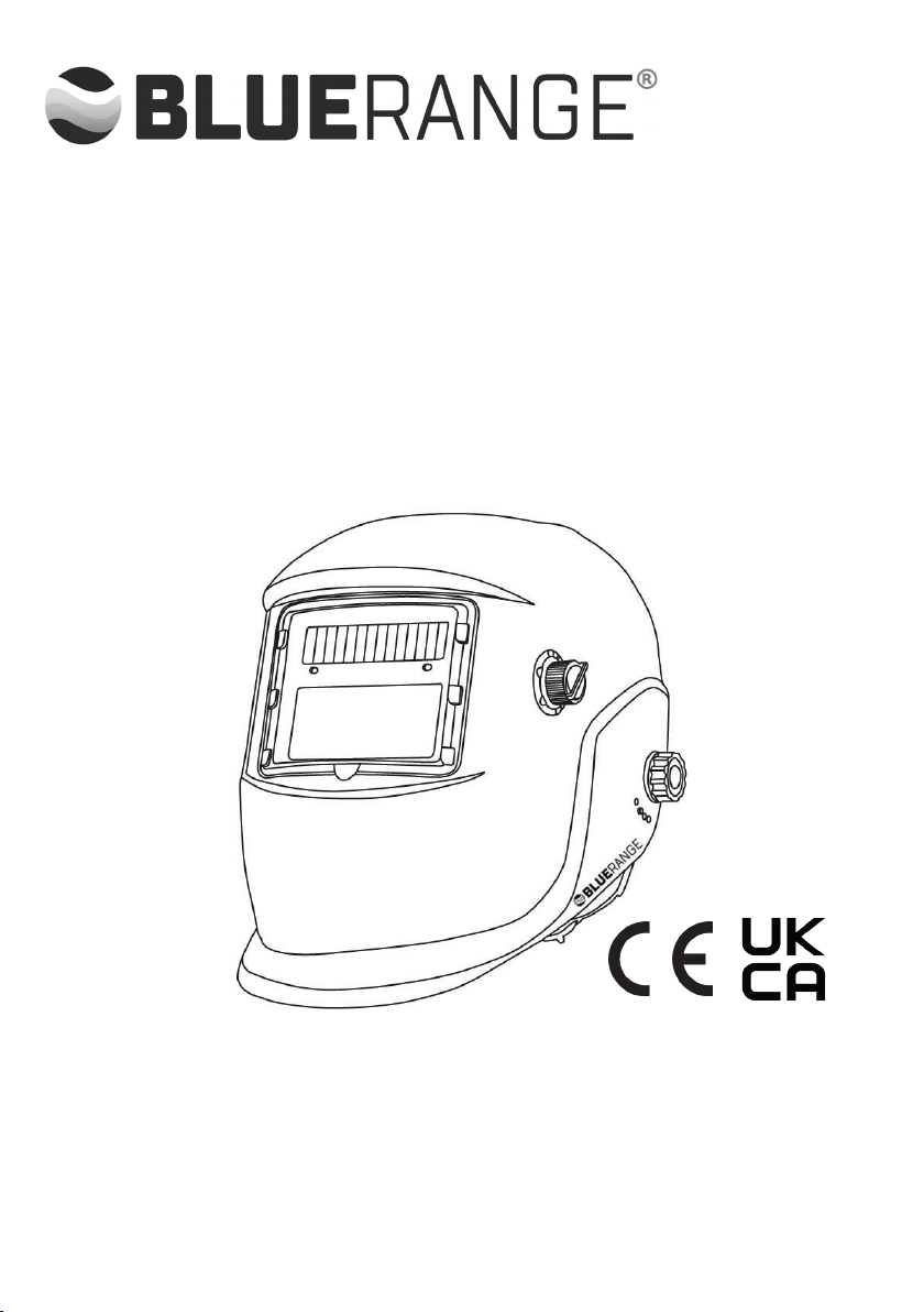
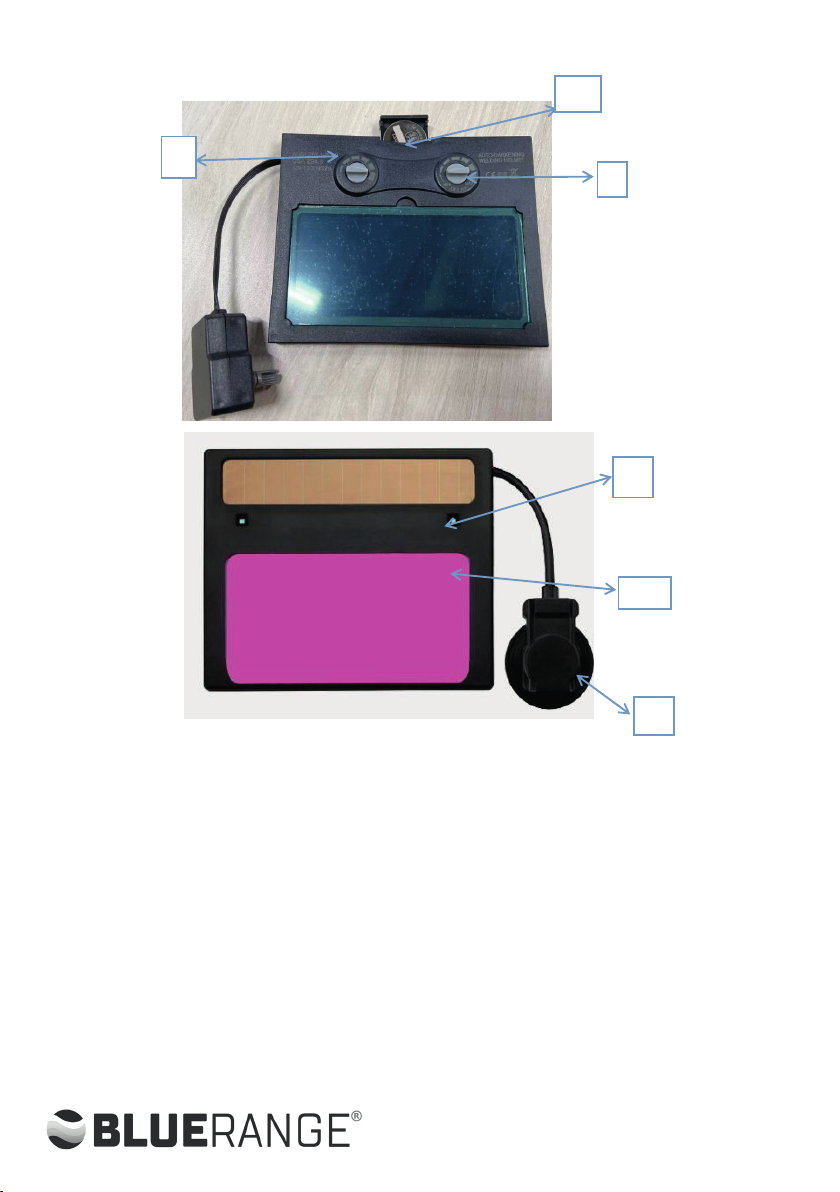
1. Delay time adjust:adjust the auto d arkening welding lter from the dark to light
time
2. Sensitity adjust :according to the operation situation to adjust the sensitity
3. Dark shade adjust: according to the operation situation to adjust the dark shade
from DIN9 DIN13
4. Replace which need to put 1pcs battery
5. Sensor: high sensitive sensors
6. High quality LCD: .light evenly image clearly
3) Operating Instructions
3.1 Before Welding
5.1.1 Ensure that the internal and external protective lms are removed from the lenses.
5.1.2 Check that the batteries have sucient power to operate the helmet. The lter cartridge can last for
5,000 working hours powered by the lithium batteries and solar cells.
3
1. delay time adjust:adjust the auto darkening welding filter from the dark to light
time
5
6
1
2
3
4

Page 4
5.1.3 Check that the arc sensors are clean and not blocked by dust or debris.
5.1.4 Check for headband tightness before each use.
5.1.5 Inspect all operating parts before use for signs of wear or damage. Any scratched, cracked, or pitted
parts should be replaced immediately before using again to avoid severe personal injury.
5.1.6 Select the shade number you require at the turn of a shade knob . Finally, be sure that the shade
number is the correct setting for your application.
Shade Guide Table
Note:
SMAW - Shielded Metal Arc Welding.
TIG GTAW - Gas Tungsten Arc (GTAW)(TIG).
MIG (Heavy) - MIG on heavy metals.
SAW Shielded Semi - Automatic Arc Welding.
MIG (Light) - MIG on light alloys.
PAC - Plasma Arc Cutting
PAW - Plasma Arc Welding
3.2 Sensitity
The sensitity control is set according to the welding process and ambient light.
3.2.1 Low Setting- suitable for high amperage welding and welding in areas with high levels of natural
sunlight.
3.2.2 Medium Setting - suitable for most indoors and outdoors welding.
3.2.3 High Setting- suitable for low amperage welding and welding in areas with low light conditions,
especially for low amperage argon-arc welding.
3.3 Grinding Mode
The welding helmet can also be used to protect the face during grinding.Switching to Grind mode will
prevent the lter cartridge from darkening when bright sparks are created.
3.4 Delay Time
Delay time refers to the time the cartridge lter is set to change from the dark to bright state aer welding
stops. The delay can be adjusted up to a one second delay.
3.4.1 The minimum delay is set between 0.1 to 0.2 seconds, suitable for spot or short welds.
3.4.2 The maximum delay time is set between 0.85 to 1.0 second, suitable for heavy current welding or
when sible light is produced.
3.4.3 Selections between minimum and maximum are suitable to most indoor and outdoor welding
operations.
6.1.3 Check that the arc sensors are clean and not blocked by dust or debris.
6.11.4 Check for headband tightness before each use.
6.1.5 Inspect all operating parts before use for signs of wear or damage. Any
scratched, cracked, or pitted parts should be replaced immediately before using
again to avoid severe personal injury.
6.1.6 Select the shade number you require at the turn of a shade knob . Finally, be
sure that the shade number is the correct setting for your application.
Shade Guide Table
Note:
SMAW-Shielded Metal Arc Welding.
TIG GTAW-Gas Tungsten Arc (GTAW)(TIG).
MIG(Heavy)-MIG on heavy metals.
SAM Shielded Semi-Automatic Arc Welding.
MIG(Light)-MIG on light alloys.
PAC-Plasma Arc Cutting
6.2. Sensitivity
The sensitivity control is set according to the welding process and ambient light.
6.2.1 Low Setting- suitable for high amperage welding and welding in areas with
high levels of natural sunlight.
6.2.2 Medium Setting - suitable for most indoors and outdoors welding.
SMAW
SAW
PAC
PAW
MIG (Heavy)
MIG (Light)
TIG GTAW
MAG / (C02)
Welding Current
(A)
Welding Type
0.5 2.5 10 20 40 80 125 175 225 275 350 450
15 15 30 60 100 150 200 250 300 400 500
1413
13 14
15
14
15
15
13
15
1211109
121110
1413121110
13
12
11109
1413121110
1413121110
1211
141312111098

6
5. Adjust the headband
5.1 Adjusts headband for proper depth on the head to ensure correct balance and
stability. (See No.1).
5.2 Adjusts the distance between the face and the lens.To adjust, adjust the
positioning screw moved to another location slot, forward or backward. Screw
down the screws.(Both sides must be equally positioned for proper vision,See
No.2)
5.3 Turn the adjusting knob located on the back of the headband left or right to
desired tightness.(See No.3)
5.4 Shift the segmental plate with different positioning hole to adjust the window
angle for clear view. (See No.4) Numbers on the adjustment slides indicate set
position so both sides can be adjusted equally.
NO.1 NO.2 NO.3 NO.4
NO.1
NO.2
NO.3
NO.4
Page 5
3.5 Adjust the headband
3.5.1 Adjusts headband for proper depth on the head to ensure correct balance and stability. (See No.1).
3.5.2 Adjusts the distance between the face and the lens.To adjust, adjust the positioning screw moved to
another location slot, forward or backward. Screw down the screws.(Both sides must be equally positioned
for proper sion,See No.2)
3.5.3 Turn the adjusting knob located on the back of the headband le or right to desired tightness.(See
No.3)
3.5.4 Shi the segmental plate with dierent positioning hole to adjust the window angle for clear ew.
(See No.4) Numbers on the adjustment slides indicate set position so both sides can be adjusted equally.
3.3 Replacing The Battery
When the battery power is low, the lter cartridge lens may not work correctly. Replace the Batteries. To
replace the battery, rst unscrew the front lens retaining frame and remove this. Locate the battery holder
at the top of the Auto Darkening Filter and slide upwards to open. Remove the old battery and replace with
a new CR2032 battery. Close the battery holder and screw the front lens retaining frame back into position.
This manual suits for next models
1
Table of contents


