Bluesky SB3000i Owner's manual

SB3000i
(SOLAR BOOST™ 3000i MPPT)
12 VOLT 30/22 AMP MAXIMUM POWER POINT TRACKING
PHOTOVOLTAIC CHARGE CONTROLLER
INSTALLATION AND OPERATION MANUAL
THIS MANUAL INCLUDES IMPORTANT SAFETY INSTRUCTIONS FOR MODEL SB3000i
SAVE THESE INSTRUCTIONS.
COVERED UNDER ONE OR MORE OF THE FOLLOWING US PATENTS
6,111,391 •6,204,645
© Blue Sky Energy, Inc. 2017 430-0034 C
FCC CFR 47 Part 15 Subpart B
This device complies with part 15 of the FCC
rules. Operation is subject to the following two
conditions: 1) This device may not cause harmful
interference, and 2) This device must accept any
interference received, including interference that
may cause undesired operations.
CONFORMS TO:
EN 61000-6-2:2005
EN 61000-6-3:2007 + A1:2011
AS/NZS 60000-6-3:2012

Blue Sky Energy –Solar Boost 3000i
1Blue Sky Energy | USA | www.blueskyenergyinc.com
TABLE OF CONTENTS
IMPORTANT SAFETY INSTRUCTIONS .................................................................................................................. 2
PRODUCT DESCRIPTION...................................................................................................................................... 2
Part Numbers and Options................................................................................................................... 3
OPERATION ....................................................................................................................................................... 3
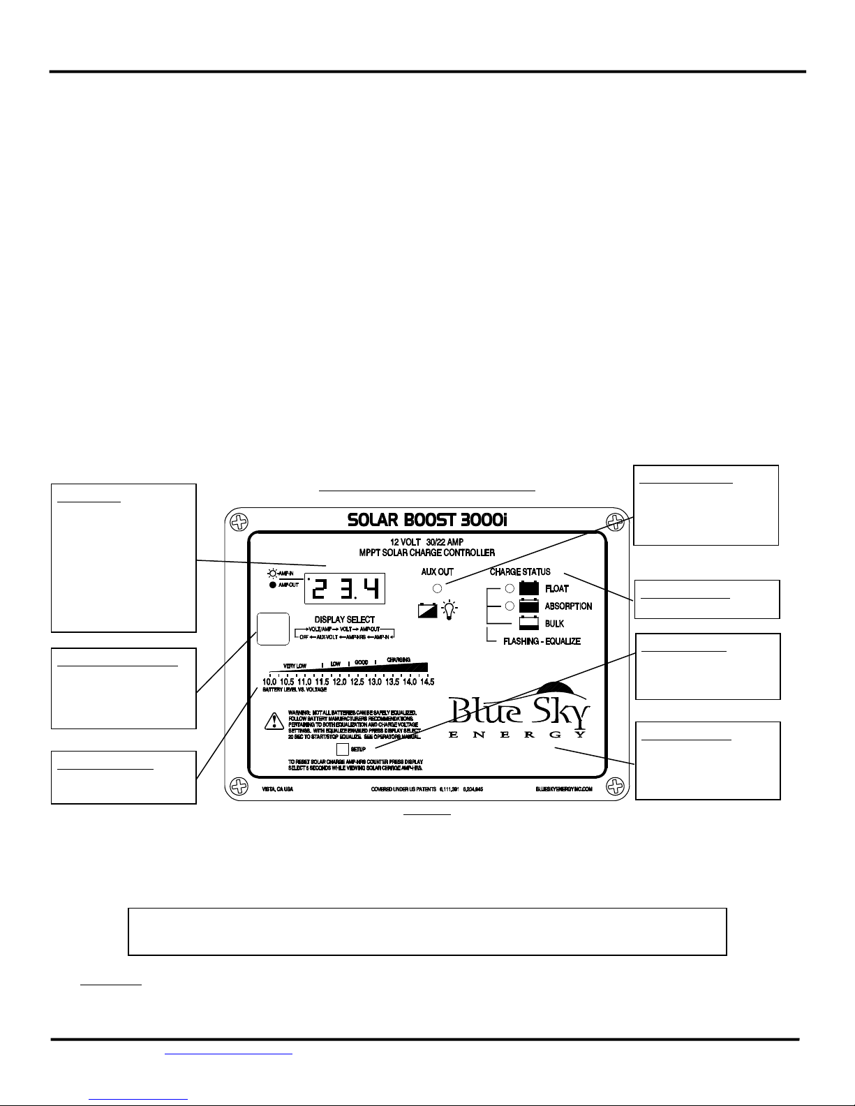
Charge Status Indication ...................................................................................................................... 3
Digital Display....................................................................................................................................... 3
Solar Charge Amp-Hour Counter.......................................................................................................... 3
Battery Level Graphic........................................................................................................................... 4
3-Stage Charge Control ........................................................................................................................ 4
Bulk Charge .................................................................................................................... 4
Absorption Charge.......................................................................................................... 4
Float Charge .....................................................................................................................4
Two Stage Charge Control.................................................................................................................... 5
Output Current Limit............................................................................................................................ 5
Optional Temperature Compensation ................................................................................................. 5
Equalization.......................................................................................................................................... 5
Maximum Setpoint Voltage Limit......................................................................................................... 5
Maximum Power Point Tracking.......................................................................................................... 6
Panel Temperature and Thermal Protection........................................................................................ 6
Multiple Charge Controllers On The IPN Network ............................................................................... 6
INSTALLATION ..................................................................................................................................................... 6
Charge And Load Control Settings........................................................................................................ 6
As Shipped Factory Default Settings............................................................................... 6
Restoring As Shipped Factory Default Settings............................................................... 7
Changing Charge And Load Control Settings .................................................................. 7
Selecting PV Modules........................................................................................................................... 8
Mounting ............................................................................................................................................. 8
Battery and PV Wiring.......................................................................................................................... 9
Optional Battery Temperature Sensor ................................................................................................. 9
Auxiliary Output ...................................................................................................................................10
Auxiliary Battery Charge.................................................................................................10
Load Controller...............................................................................................................10
Dusk–To–Dawn Lighting Control ....................................................................................11
Battery & PV Power Connect/Disconnect Order..................................................................................11
Connecting The Battery..................................................................................................11
Connecting PV Modules .................................................................................................11
Installing A Multi-Controller System Using The IPN Network...............................................................11
Multi-Controller Wiring And Setup.................................................................................12
TROUBLESHOOTING GUIDE ................................................................................................................................12
SPECIFICATIONS ..................................................................................................................................................15
FIVE YEAR LIMITED WARRANTY..........................................................................................................................15
TABLES AND FIGURES
Table 1 Charge Status ................................................................................................................. 3
Table 2 Charge And Load Control Settings.................................................................................. 7
Table 3 Maximum Conductor Pair Length –3% Voltage Drop.................................................... 9
Figure 1 Front Panel Operation & Indicators................................................................................ 4
Figure 2 Factory Charge Voltage Setpoints -vs.- Battery Temperature........................................ 5
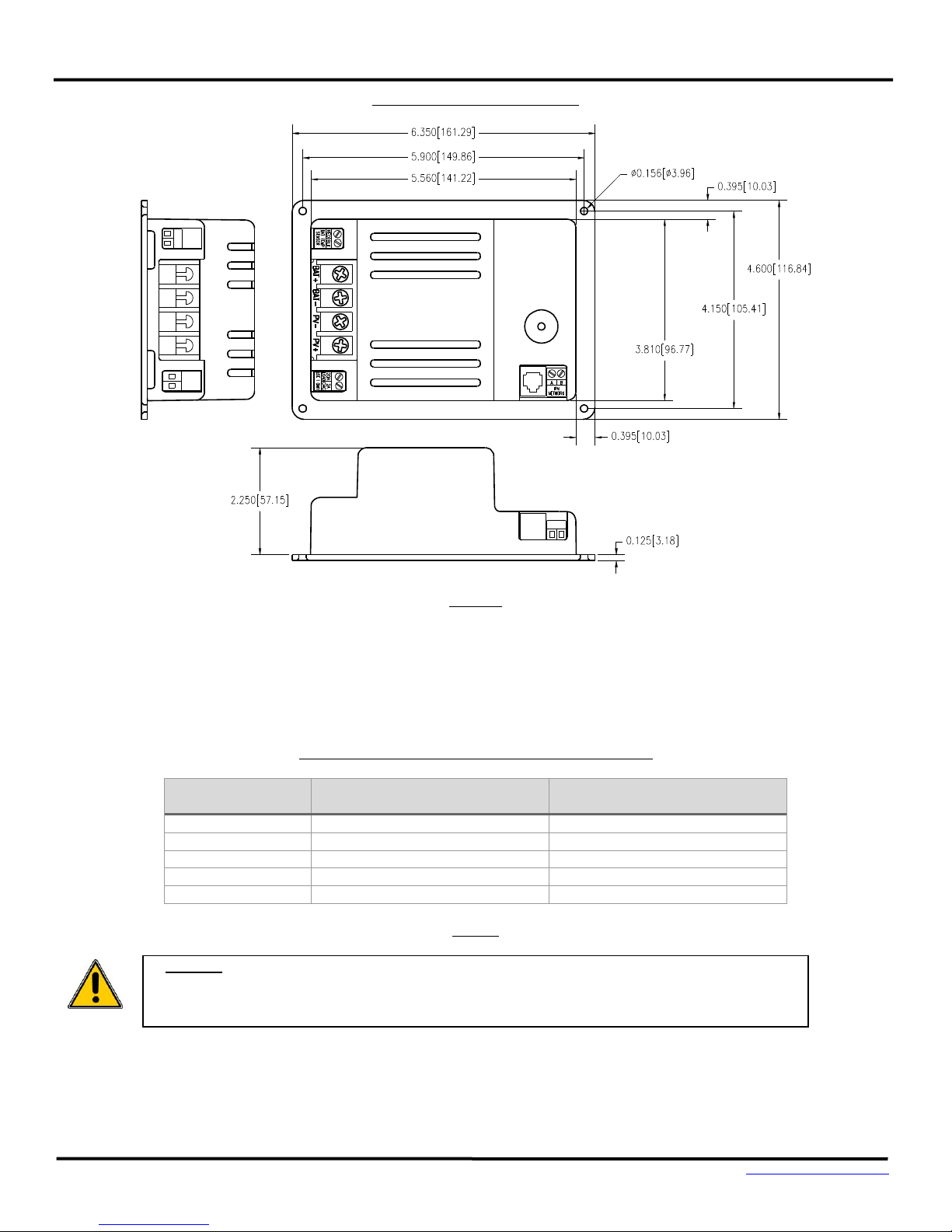
Figure 3 Detailed Dimensional Drawing ....................................................................................... 8
Figure 4 Wiring Diagram .............................................................................................................. 9
Figure 5 Auxiliary Output Wiring Diagram....................................................................................10
Figure 6 IPN Network Wiring........................................................................................................12

Installation and Operation Manual
Blue Sky Energy | USA | www.blueskyenergyinc.com 2
IMPORTANT SAFETY INSTRUCTIONS
This manual contains important instructions for Model SB3000i - SAVE THESE INSTRUCTIONS
1. Refer installation and servicing to qualified service personnel. Incorrect installation or use may result in risk of electric shock or fire. No user
serviceable parts in this unit.
2. To reduce the risk of electric shock, fire or personal injury, the following symbols are placed throughout this manual to indicate dangerous
conditions, or important safety or operational instructions.
WARNING
CAUTION
IMPORTANT
Indicates dangerous conditions or electric
shock potential. Use extreme caution.
Indicates items critical to safe installation
or operation of the unit.
Follow these instructions closely for
proper operation of the unit
3. PERSONAL PRECAUTIONS
a) Working in the vicinity of lead-acid batteries is dangerous. Batteries produce explosive gasses during normal operation.
b) To reduce risk of battery explosion, follow these instructions and those published by battery manufacturer and manufacturer of any equipment
you intend to use in vicinity of battery.
c) Someone should be within range of your voice or close enough to come to your aid when you work near a lead-acid battery.
d) Have plenty of fresh water and soap nearby in case battery acid contacts skin, clothing or eyes.
e) Wear complete eye protection and clothing protection. Avoid touching eyes while working near battery.
f) If battery acid contacts skin or clothing, wash immediately with soap and water. If acid enters eye, immediately flood eye with running cold
water for at least 15 minutes and get medical attention immediately.
g) NEVER SMOKE or allow a spark or flame in vicinity of battery.
h) Be extra cautious to reduce risk of dropping metal tool onto battery. It might spark or short circuit battery or other electrical part that may cause
explosion.
i) Remove personal metal items such as rings, bracelets and watches when working with a lead-acid battery. A lead-acid battery can produce a
short circuit current high enough to weld a ring or the like to metal, causing a severe burn.
j) Remove all sources of power, photovoltaic and battery before servicing or installing.
4. CHARGER LOCATION & INSTALLATION
a) This unit is designed to charge 12 volt (6 cell) flooded or sealed type lead-acid chemistry batteries within the range of 20 to 2,000 amp-hours.
Follow battery manufacturers charging recommendations when considering this unit for use with other battery chemistry.
b) This unit employs components that tend to produce arcs or sparks. NEVER install in battery compartment or in the presence of explosive gases.
c) This unit must be installed and wired in accordance with National Electrical Code, ANSI/NFPA 70.
d) Over current protection for the battery must be provided externally. To reduce the risk of fire, connect to a circuit provided with 40 amp
maximum branch-circuit over current protection in accordance with National Electrical Code, ANSI/NFPA 70 with 36 cell modules, or 30 amp
maximum with 60 cell modules. Do not connect a PV array capable of delivering greater than 24 amps of short circuit current ISC at STC with 36
cell modules, or 11.8 amps with 60 cell modules.
e) Over current protection for the auxiliary load control output or auxiliary battery charge output must be provided externally. To reduce the risk
of fire, connect to load or auxiliary battery with 25 amp maximum over current protection in accordance with National Electrical Code,
ANSI/NFPA 70.
f) Insure that charge parameters are properly configured for the battery being charged as recommended by the battery manufacturer.
g) This unit is not water tight. Do not expose to rain, snow or excessive moisture.
h) Insure all terminating connections are clean and tight. Tighten Battery and PV compression terminals to 15.9 in-lb (1.80 nm), battery
temperature sensor and IPN Network compression terminals to 2.1 in-lb (0.24 nm), and auxiliary output compression terminals to 6 in-lb (0.67
nm).
5. PREPARING TO CHARGE
a) Never charge a frozen battery.
b) Be sure battery is mounted in a well ventilated compartment.
c) Add distilled water in each cell of a lead-acid battery until battery acid reaches level specified by battery manufacturer.

Blue Sky Energy –Solar Boost 3000i
3Blue Sky Energy | USA | www.blueskyenergyinc.com
PRODUCT DESCRIPTION
The Solar Boost 3000i is a Maximum Power Point Tracking (MPPT) solar charge controller able to charge 12V batteries at up to 30 amps from 36 cell
12V PV modules. Patented MPPT technology operates the modules electrically in a manner that harvests all available PV power and can increase
charge current up to 30% or more compared to conventional PWM type controllers. The voltage step-down operation of the MPPT power
converter also allows use higher voltage 60 cell grid-tie PV modules at up to 22 amps of output current producing a charge current increase
approaching 200% with 60 cell modules. The 3000i’s sophisticated and fully adjustable 3-stage plus equalization charge control system optimally
charges flooded, GEL and AGM lead-acid chemistry batteries. Electronic protection is provided against voltage transients, over temperature, over
current, short circuit, swapped battery & PV, and reverse battery & PV polarity. A very low power LED display is provided to monitor PV charge
performance and includes a resettable amp-hour counter which computes total PV amp-hours produced. A user configurable auxiliary output is also
provided which can serve as either a 20 amp LVD load controller, a 20 amp lighting controller with LVD, or a 2 amp auxiliary battery charger for a
second battery such as the engine start battery in an RV. To allow easy system expandability the 3000i may also operate as an IPN Network Master
controlling up to 7 Blue Sky Energy IPN compatible charge controllers such as the SB3024iL. Blue Sky Energy’s IPN Network allows multiple charge
controllers to communicate with each other and coordinate their activities to charge the battery as a single coordinated charging machine.
PART NUMBERS AND OPTIONS
•SB3000i.............Solar Boost 3000i solar charge controller •930-0022-20 …………..Optional battery temperature sensor
•IPNPRO-S..........Optional IPN ProRemote battery system monitor •720-0011-01 …………..Optional wall mounting box, black powder coated
•UCM..................Optional Universal Communication Module for system access over the Internet
OPERATION
Basic charge control operations are fully automatic and require no operator intervention. When sufficient PV power is available the 3000i will
switch to a Charge ON state and begin charging the battery. The particular charge mode the 3000i will operate in will vary depending on the needs
of the battery and available PV charge current. When insufficient PV current is available to charge the battery the 3000i will switch to a Charge Off
state and the PV array will be disconnected from the battery to prevent unwanted current drain. There is a 5 second turn-on delay, and a 45 second
turn-off delay.
➢The 3000i operates on battery power, not PV power. Insure that voltage on the battery terminals of the 3000i is
always the same as actual battery voltage within a few 10ths of a volt and greater than 9 volts for proper
operation. Note that the front panel serves as a heatsink for power control devices and may become quite warm
during normal operation.
➢CAUTION: Do not disconnect the battery while the 3000i is in a Charge ON state. A healthy battery is a key
component of the charge voltage control system and provides charge voltage filtering. Sudden removal of the battery
while the 3000i is charging will produce voltage spikes at the 3000i’s battery terminals which may damage 12 volt
appliances still connected to the 3000i, especially when using higher voltage 60 cell PV modules.
IF THE BATTERY MUST BE DISCONNECTED, REMOVE PV POWER FIRST.
CHARGE STATUS INDICATION
Present charge status of the 3000i is indicated using two charge status LED’s, Absorption & Float. If net battery charge current is greater than about 3 to
5 amps per 100 amp-hours of battery capacity the charge status indicator can provide a rough indication of battery state of charge.
CHARGE STATUS
CHARGE STATUS LED’s
CHARGE MODE
APPROXIMATE CHARGE LEVEL
ABSORPTION & FLOAT OFF
CHARGE OFF
ABSORPTION & FLOAT ON
BULK
<70% FULL
ABSORPTION ON –FLOAT OFF
ABSORPTION
70% - 95% FULL
ABSORPTION OFF –FLOAT ON
FLOAT
FULLY CHARGED
ABSORPTION & FLOAT
ALTERNATELY BLINKING
EQUALIZE
TABLE 1
DIGITAL DISPLAY
When the 3000i completes self-test the VOLT/AMP display mode is active. This mode displays Battery Voltage continuously if the 3000i is in a Charge Off
state, or alternates between Battery Voltage & Output Charge Current if the 3000i is charging the battery. The AMPS indicator in the upper left of the
display will be on solid when displaying 3000i output current, or blinking when displaying PV input current. To provide good readability yet minimize
the likelihood of the display being objectionably bright at night an automatic night time dimming feature dims the display at night when the 3000i is
in a Charge Off state. Other display modes may be selected using the Display Select push-button. Each brief press of Display Select selects the next
display mode as shown on the front panel graphic of Figure 1. VOLT shows Battery Voltage, AMP-OUT shows 3000i Output Charge Current, AMP-IN
shows PV Input Current, and AMP-HRS shows total PV Amp-Hours produced since the amp-hour counter was last cleared. If the 3000i is part of a multi-
Title:
From AutoCAD Drawing "f:\RVpower\autocad\library\WAR-CAUT"
Creator:
AutoCAD
Preview:
This EPS picture was not saved
with a preview included in it.
Comment:
This EPS picture will print to a
PostScript printer, but not to
othertypes of printers.

Installation and Operation Manual
Blue Sky Energy | USA | www.blueskyenergyinc.com 4
controller system using the IPN Network the 3000i’s display will show the total of all controllers on the network. AUX-VOLT shows voltage on 3000i’s the
auxiliary output. When the auxiliary output is configured for Auxiliary Battery Charge (factory default) and the 2 amp auxiliary charge output is
connected to an auxiliary battery (such as the engine start battery in a Motorhome) the voltage of the auxiliary battery is displayed. If the auxiliary
output is configured for Load Control, the voltage displayed is that applied to the load.
SOLAR CHARGE AMP-HOUR COUNTER
The battery essentially serves as a “storage tank”, with the battery storing electrical energy in units referred to as amp-hours. Amp-hours are
computed by multiplying current in amps X time in hours. For example 20 amp-hours may be a current of 10 amps flowing for 2 hours, or may be 1
amp flowing for 20 hours. The battery receives and stores amp-hours when being charged, and then delivers those stored amp-hours when being
discharged. The amp-hour counter displays total solar charge amp-hours accumulated since the last time the counter was cleared up to a maximum
count of 999 amp-hours. Amp-hour production varies widely with operating conditions, but as a very broad brush approximation 100 watts of PV
modules can deliver up to a maximum of about 30 amp-hours per day. Any partial shading, lower sun intensity, shorter days, or time spent in
Absorption or Float will decrease amp-hours produced. The present amp-hour count may be cleared by pressing Display Select for 5 seconds while
viewing amp-hours on the display.
BATTERY LEVEL GRAPHIC
The 3000i provides a battery level graphic on the front panel which indicates approximate battery level versus battery voltage. Generally a higher voltage
is better than a lower voltage. A battery that is being charged will typically range in voltage from about 12.5 volts after charge commences, to 14.0 volts
or greater when the battery is highly charged. Once charge stops and the battery begins discharging and delivering power to a load it is normal for
battery voltage to drop. A battery under a light load of about 1 amp per 100 amp-hours of battery capacity may range between about 12.5 volts when
the battery is full, down to perhaps 12.0 volts when the battery is about 50% discharged. Battery voltage during discharge will tend to be higher under
light load and lower under a heavier load.
Do not think of these voltage values as absolutes but rather as a broad brush indication of approximate battery charge level. Voltage at a particular state
of charge will vary with battery size, age, construction, temperature, and with the level of charge or discharge current. Most battery manufacturers
recommend not discharging below about 50% DOD (depth of discharge) to promote improved battery performance and life. Avoid allowing battery
voltage to drop below about 11.5 volts, and NEVER allow battery voltage to drop below 10.0 volts. If a highly accurate battery charge level indication is
desired, consider installing an optional IPN ProRemote display.
FRONT PANEL OPERATION & INDICATORS
FIGURE 1
3-STAGE CHARGE CONTROL
The 3000i is factory configured for a 3-stage charging process, Bulk, Absorption and Float, which is fully automatic and requires no operator
intervention. The 3-stage charge process applies a somewhat higher Absorption charge voltage to charge the battery quickly and safely. Once the
battery is fully charged a somewhat lower Float voltage is applied to maintain the battery in a fully charged state without excessive water loss.
➢The charge control system always starts in Absorption and will return to Absorption upon exiting Current Limit
or Equalization. Following a 10 second delay in Absorption the 3000i may move on to other charge modes based
on battery and system needs.
Bulk Charge
The 3000i will switch to Bulk charge when battery voltage remains below the present Charge Voltage setpoint. During Bulk the 3000i delivers as
much charge current as possible to rapidly recharge the battery. During Bulk it is a combination of battery size, state of charge and available
charge current that determine battery voltage, not the 3000i.
Auxiliary Output LED
Indicates when the auxiliary
output is ON, either charging
an auxiliary battery or
powering a load.
Setup Push-Button
Used with Display Select to
view or change all setup
parameters.
Digital Display
May show battery voltage,
input/output charge current,
solar charge amp-hours or
auxiliary output voltage.
AMP indicator will be on
solid for output current or
blinking for PV input current.
Display automatically dims at
night.
Display Select Push-Button
Selects display mode. May
also be used to clear solar
charge amp-hours or
start/stop Equalize.
Front Panel Heating
Panel serves as a heatsink for
power control devices, may
become quite warm during
normal operation.
Battery Level Graphic
Shows approximate battery
level vs. battery voltage.
Charge Status LED’s
Shows present charge mode.

Blue Sky Energy –Solar Boost 3000i
5Blue Sky Energy | USA | www.blueskyenergyinc.com
Absorption Charge
Once the battery recovers sufficient charge for battery voltage to rise to the Absorption Charge Voltage setpoint (factory set to 14.4V), charge
current is reduced as necessary to hold the battery at the Absorption Voltage. The 3000i will return to Bulk should battery voltage remain below
the Absorption Voltage setpoint for more than 10 seconds. The 3000i remains in Absorption until the battery is fully charged as determined by
either;
1) The 3000i remains continuously in Absorption for the Absorption Charge Time period (factory set to 2 hours).
OR
2) With the optional IPN ProRemote display and battery system monitor, net battery charge current decreases to the Float Transition
Current (factory set in the ProRemote to 1.5 amps per 100 amp-hours of battery capacity).
Float Charge
Once the battery is fully charged a somewhat lower Float Voltage (factory set to 13.2V) is applied to maintain the battery in a fully charged
state without excessive water loss. The 3000i will return to Absorption should battery voltage remain below the Float Voltage setpoint for
more than 10 seconds.
2-STAGE CHARGE CONTROL
The 3000i may be configured for 2-stage charge control if desired by setting the Float Charge Voltage setting to “OFF” (NO Float).
OUTPUT CURRENT LIMIT
Should conditions be present where the PV modules are able to produce more than 30 amps of output current with 36 cell PV modules, or 22 amps
with 60 cell PV modules, the 3000i will automatically limit output current to this value. Note that when current drops and the 3000i exits current
limit it will first enter Absorption on its way back to Bulk even though battery voltage may be below the Absorption Charge Voltage setpoint.
➢WARNING: Current limit should be thought of as transient PV over current protection and not a normal mode
of operation. If the 3000i enters 30 amp or 22 amp current limit on a regular basis it is possible that excessive PV
power is connected. Confirm that the PV modules do not exceed ratings shown in the Selecting PV Modules
section.
OPTIONAL TEMPERATURE COMPENSATION
The charge voltage required by batteries changes with battery temperature. Temperature compensation of charge voltage enhances battery
performance and life while decreasing battery maintenance. Temperature compensation of charge voltage can be provided using the optional
battery temperature sensor (BSE p/n 930-0022-20). The default compensation factor of –30mV/C (–5.00mV/C/cell) is typically appropriate for
most lead-acid chemistry batteries including GEL and AGM. If a proper temperature sensor signal is not detected the 3000i will operate as if battery
temperature is 25C.
FACTORY DEFAULT CHARGE VOLTAGE SETPOINTS -VS.- BATTERY TEMPERATURE
FIGURE 2
EQUALIZATION
➢WARNING: Not all batteries can be safely equalized. Equalization should be performed only on vented liquid
electrolyte lead-acid batteries. Always follow battery manufacturers recommendations pertaining to equalization.
Equalization applies a relatively high charge voltage producing significant battery gassing. Prior to performing
equalization disconnect equipment that cannot tolerate the high equalization voltage which is temperature
compensated as shown above.
Equalization is a controlled overcharge used to bring all battery cells up to the same specific gravity and state of charge. The 3000i may be configured to
perform an automatic equalization on periodic basis, or a manual equalization. Since sealed batteries should not be equalized the factory default
settings have Equalize Enable (EqE) set to OFF to disable automatic or manual equalization. Equalization may be enabled by setting Equalize Enable to
ON as described in the Charge And Load Control Settings section. When an equalization cycle is being performed the Float and Absorption charge status

Installation and Operation Manual
Blue Sky Energy | USA | www.blueskyenergyinc.com 6
LED’s will alternately blink. With equalize enabled the 3000i will perform an automatic equalization at the factory default settings of 15.2V for 2 hours
every 30 days which is typically suitable for most flooded lead-acid batteries. When set for automatic equalization the cycle will begin when the set
number of days since the last equalization has elapsed, and the charge control system has switched to Float. When set for manual equalization (Eqd set
to 00) an automatic equalization will not occur. Whether set for automatic or manual the process may be started or stopped manually by pressing the
Display Select push-button for 20 seconds. Once equalization has started the equalize timer will not count down unless battery voltage is at the equalize
voltage setpoint which is temperature compensated as shown above. Therefore obtaining a proper 2 hour equalization will require longer than 2 hours
to complete depending on available charge current. Note that at least 3.5 amps of net charge current per 100 amp-hours of battery capacity is typically
required to properly equalize a battery. If equalization does not complete during the charging day it will resume where it left off the next charging day,
but will automatically cancel if unable to complete within 24 hours. The equalize day counter is reset whenever an equalization cycle is started.
MAXIMUM SETPOINT VOLTAGE LIMIT
The maximum setpoint voltage limit places a maximum limit or ceiling on the charge voltage setpoint used by the 3000i in all charge modes to
prevent inverters or other equipment from shutting down due to excess voltage. Regardless of initial setpoints, charge mode or temperature
compensation the 3000i will not use a charge voltage setpoint greater than the maximum setpoint voltage limit (uPr) factory set to 15.5V. Note that
voltage may briefly exceed this value by 0.1 –0.2V as the system responds to sudden changes in load or PV power.
MAXIMUM POWER POINT TRACKING (MPPT)
The 3000i’s patented MPPT technology can increase charge current up to 30% or more compared to conventional PWM controllers operating 36
cell PV modules. Principal operating conditions affecting current boost performance are PV cell temperature and battery voltage, with lower PV
temperature and lower battery voltage producing greater charge current increase. In cool comfortable temperatures most systems see about 10 –20%
increase. Increase may go to zero in hot temperatures, whereas charge current increase may easily exceed 30% with a discharged battery and freezing
temperatures. MPPT also allows efficient use of higher voltage 60 cell modules by converting their much higher voltage down to battery voltage.
Ignoring conversion losses the conversion process produces an output current roughly equal to PV current times the ratio of PV voltage to battery
voltage. If a 60 cell module is operating at 25V with 5 amps of output, and battery voltage was 13V, output charge current from the 3000i would be
about 5 amps times 25V 13V or about 9.6 amps. For a more complete MPPT description see “What Is MPPT and how does it work?” on the FAQ page
at www.blueskyenergyinc.com.
PANEL TEMPERATURE AND THERMAL PROTECTION
Internal power control devices use the front panel as a heatsink. It is normal for the front panel to become quite warm to the touch when the 3000i
is operating normally. Front panel heating will be the greatest when the 3000i is processing either very high power or very low power. When
mounted to a vertical surface with good ventilation, the 3000i can deliver full output in an ambient temperature of up to 45C (113F). If an over
temperature condition exists, the 3000i will simply cycle on and off to keep internal temperature within acceptable limits.
MULTIPLE CHARGE CONTROLLERS ON THE IPN NETWORK
The 3000i may also operate as an IPN Network Master controlling up to 7 remote Blue Sky Energy IPN compatible charge controllers such as the
SB3024iL or SB2512iX-HV. The IPN Network allows multiple charge controllers to communicate with each other and coordinate their activities to
charge the battery as a single coordinated charging machine. The IPN Network allows an existing 3000i installation to be expanded greatly in power
handling capability by adding charge additional controllers and PV modules with all controllers displaying through the existing 3000i display.
➢When serving as an IPN network Master the 3000i’s display will show the sum of all controllers on the network
for input current, output current and solar charge amp-hours. If a remote Slave controller has good PV input but
the 3000i does not, the 3000i’s charge control system will properly direct the Slaves as indicated on the 3000i’s
Charge Status LED’s, but the 3000i’s display will be dim while the 3000i’s own power controller remains off. The
display will become bright once the 3000i receives good PV input.
INSTALLATION
➢WARNING: Read, understand and follow the Important Safety Instructions in the beginning of this manual before
proceeding. This unit must be installed and wired in accordance with National Electrical Code, ANSI/NFPA 70. Over
current protection must be provided externally. To reduce the risk of fire, connect to a circuit provided with 40 amp
maximum branch-circuit over current protection in accordance with National Electrical Code, ANSI/NFPA 70 with 36
cell modules, or 30 amp maximum with 60 cell modules. Do not connect a PV array capable of delivering greater
than 24 amps of short circuit current ISC at STC with 36 cell modules, or 11.8 amps with 60 cell modules. Do not
connect BAT–and PV–together external to the unit. To reduce risk of electric shock or product damage, remove all
sources of power before installing or servicing. Figures 4 and 5 show generalized connections only and are not
intended to show all wiring, circuit protection and safety requirements for a photovoltaic electrical system.
➢CAUTION: The 3000i is protected against reverse battery and PV polarity, and swapped PV and battery
connections, but will be damaged by reverse battery to the PV terminals. Transient voltage lightning protection is
provided, but steady state voltage in excess of 50VDC on the battery or PV terminals will damage the unit. Damage
of either type voids the limited warranty.
CHARGE AND LOAD CONTROL SETTINGS
The 3000i contains various charge control and load control settings all of which are preconfigured at the factory to the default settings shown
below. Most installations require no changes to these settings which are typically suitable for most flooded, GEL and AGM lead-acid chemistry
batteries. Check with your battery manufacturer to confirm that these settings are suitable for your particular battery.

Blue Sky Energy –Solar Boost 3000i
7Blue Sky Energy | USA | www.blueskyenergyinc.com
➢WARNING: If charge parameter settings are changed, confirm that the new settings comply with the battery
manufacturers recommendations. DO NOT enable equalization for sealed lead-acid batteries such as GEL and AGM.
As Shipped Factory Default Settings
•Charge mode ....................................... 3-stage •Equalize enable ................................................ .. Off (disabled)
•Absorption voltage ............................. 14.4V •Equalize time ................................................... .. 2.0 hours
•Absorption time .................................. 2.0 hours •Equalize voltage ............................................... .. 15.2V
•Float voltage ........................................ 13.2V •Auto equalize days ........................................... .. 30 days
•Maximum setpoint voltage limit ......... 15.5V •Temperature compensation factor ................. .. 5.00mV/C/cell
•Auxiliary output mode ....................... Aux Bat Charge •PostDusk lighting timer .................................. .. Off (disabled)
•LVD on voltage ................................... 12.6V •PreDawn lighting timer ................................... .. Off (disabled)
•LVD off voltage ................................... 11.5V •Middle of the night lighting control dimming... 0%
Restoring As Shipped Factory Default Settings
1. Remove both PV and battery power. 4. After at least 5 seconds, release Setup.
2. Apply battery power while pressing & holding the Setup push-button. 5. Confirm display resumes normal operation.
3. Following display self-test, confirm display shows software revision 6. The 3000i is now set to as shipped factory defaults.
(e.g., r1.4) & Charge Status LED’s remain on while Setup is held.
Changing Charge And Load Control Settings
3000i charge parameter settings may be viewed or changed at any time using a combination of the Setup and Display Select push-buttons.
There are two modes of setup operation, Viewing a setting and Changing a setting. Basic operation is to go from Normal Operation to Viewing
Mode, Viewing Mode to Changing Mode, and then from Changing mode back to Viewing mode, and Viewing Mode back to Normal Operation.
All settings are stored in Flash memory and are retained if power is lost.
CHARGE AND LOAD CONTROL SETTINGS
Parameter viewing mode
toggles between setting text
and value of that setting
Setting Range
Setting
Steps
Description
Setting Text
Default Setting
AbS
14.4
12.0V –17.0V
0.1V
Absorption charge voltage
Abt
2.0
0.0 –10.0 hrs
0.5 hrs
Absorption charge time
FLt
13.2
12.0V –17.0V
0.1V
Float charge voltage
Set to oFF (one step below 12.0) for 2-stage charge
EqU
15.2
12.0V –17.0V
0.1V
Equalize charge voltage
Eqt
2.0
0.5 –10.0 hrs
0.5 hrs
Equalize charge time
Normal Display Operation
Parameter Viewing mode
Parameter Changing Mode
Viewing a setting
To enter the Viewing Mode press Setup 5 seconds and release when AbS appears in the display. The first parameter
to be shown is the Absorption Charge Voltage setting. The display will alternate between AbS and 14.4 to show the
present Absorption Charge Voltage setting is 14.4V.
A brief press of Setup within 5 seconds will move to the next setting shown in Table 2, Absorption Charge Time
where the display will now alternate between Abt and 2.0 to show the present Absorption Charge Time setting is
2.0 hours. Remaining settings may be viewed by repeatedly pressing Setup to move to the desired setting. To exit
Viewing Mode and return to normal operation, do not press Setup for 5 seconds.
Changing a setting
To enter the Changing Mode, first enter the Viewing Mode for the setting to be changed. While in Viewing Mode
for that setting, press Setup 5 seconds to enter the Changing Mode for that setting. The present setting value will
begin blinking rapidly indicating that you have entered the parameter changing mode for that setting. Use Display
Select to scroll through the available values until the desired value is reached. With the desired new value blinking
in the display press Setup 5 seconds to save the new setting. Once the new setting is saved the display will revert
back to the Viewing Mode showing the new saved value for that setting.
If neither Setup or Display Select is pressed within 5 seconds while in the Changing Mode, the change request is
abandoned and the display reverts back to Viewing Mode without changing the setting.

Installation and Operation Manual
Blue Sky Energy | USA | www.blueskyenergyinc.com 8
Parameter viewing mode
toggles between setting text
and value of that setting
Setting Range
Setting
Steps
Description
Setting Text
Default Setting
Eqd
30
10 –400
5 days
Days between automatic equalization cycles
Setting of zero (00) disables automatic equalization
EqE
oFF
on or oFF
–
Master equalize enable/disable
Set to on to enable either automatic or manual equalization
uPr
15.5
12.0V –17.0V
0.1V
Maximum setpoint voltage limit
btc
500
(–5.00mV/C/cell)
000 –800
(–0.00 to –8.00
mV/C/cell)
10
(10mV/C/cell)
Battery temperature compensation factor
(decimal point missing in display
such that 500 = –5.00mV/C/cell)
(default provides overall factor of –30mV/C for 6 cell 12V battery)
Charge control related items above Load control related items below
out
ch9
ch9 or Lod
–
Selects Auxiliary Output functionality for
Auxiliary Bat Charge (ch9), or Load/Lighting control (Lod)
Lon
12.6V
5.0V –17.0V
0.1V
Load control LVD on threshold
LoF
11.5V
5.0V –17.0V
0.1V
Load control LVD off threshold
PSt
oFF
0.5 –20.0 hrs
0.5 hrs
PostDusk lighting timer, set to oFF (one step below 0.5) to
disable
PrE
oFF
0.5 –20.0 hrs
0.5 hrs
PreDawn lighting timer, set to oFF (one step below 0.5) to
disable
PEr
0
0 –90%
10%
Middle of the night % brightness (between PostDusk & PreDawn
timers)
TABLE 2
SELECTING PV MODULES
The 3000i is designed to operate conventional 12V 36 cell PV modules or higher voltage 60 cell modules. It is not intended for use with 72 cell
modules. If multiple PV modules are used best MPPT current boost performance will be obtained if all PV modules are identical. Dissimilar modules
should have VMP values within 0.5V or better and be of the same basic cell technology so their VMP will tend to track as operating conditions
change. If module types are very different consider using a separate charge controller for each module type to obtain the best MPPT current boost
performance. When multiple controllers are used on the IPN Network each controller independently MPPT’s their modules to their best. Do not mix
36 cell and 60 cell modules on the same controller. Select PV modules that do not exceed the maximum ratings shown below, and preferably
produce IMP of at least 3.5 amps (2 amps with 60 cell modules) per 100 amp-hours of battery capacity.
Voltage, current and power produced by PV modules fluctuate widely with operating conditions. As a result a set of test conditions referred to as
Standard Test Conditions (STC)are used to rate modules in a meaningful manner and accurately predict real world performance. STC ratings are
not maximum or optimal ratings. Conditions can be present where VOC and ISC approach 1.25 times STC ratings which is why National Electrical Code
and our recommendations call for 1.25 derating of both VOC and ISC. Yet in real world conditions IMP actually seen is commonly only about 75 –80%
of IMP at STC.
Key PV module specifications;
PMAX Maximum power in watts (PMAX = VMP x IMP)
VOC Voltage with module open circuit (typically 20 –22V for 12V nominal 36 cell modules)
VMP Voltage where module produces Maximum Power (typically 17 –18V for 12V nominal 36 cell modules)
IMP Current where module produces Maximum Power
ISC Current with module Short Circuit
PV Cell Count
Maximum PV
Power @ STC
Automatic
Output Current
Limit
Maximum PV
Isc @ STC
Maximum PV
VOC @ STC
Recommended range of
VMP @ STC
36 Cell
400W
30A
24A
24.0V
16.0 –19.0V
60 Cell
290W
22A
11.8A
40.0V
24.0V –31.0V
MOUNTING
➢CAUTION: The front panel may become quite warm to the touch during normal operation. Mount the 3000i
vertically to promote air flow and cooling, do not enclose in a confined space and avoid mounting in direct sunlight.
The 3000i is not watertight and must be protected from rain, snow and excessive moisture. Corrosion resulting from
liquid water or excessive moisture voids the limited warranty. An optional black powder coated deluxe mounting box
is available as BSE p/n 720-0011-01. The optional mounting box is the same X,Y dimension as the 3000i front panel
and 2.75” (7cm) deep.

Blue Sky Energy –Solar Boost 3000i
9Blue Sky Energy | USA | www.blueskyenergyinc.com
DETAILED DIMENSIONAL DRAWING
FIGURE 3
BATTERY AND PV WIRING
A desirable installation will produce a total system wiring voltage drop of 3% or less. The lengths shown in Table 3 are one way from the PV modules to
the battery with the 3000i located along the path. Length can be increased inversely proportional to actual PV IMP such that if current was reduced by 1/2
wire lengths could be doubled and still provide the same 3% voltage drop. For 60 cell modules use two wire sizes larger than shown (e.g., 8awg rather
than 12awg) for the wire section between the 3000i and the battery.
MAXIMUM CONDUCTOR PAIR LENGTH –3% VOLTAGE DROP
WIRE GAUGE
AWG
60 CELL MODULES @11.8AMP INPUT
FEET / METERS
36 CELL MODULES @ 24AMPS INPUT
FEET / METERS
12 AWG
17.9 / 5.5
5.3 / 1.6
10 AWG
28.5 / 8.7
8.5 / 2.6
8 AWG
45.3 / 13.8
13.5 / 4.1
6 AWG
71.2 / 21.7
21.4 / 6.5
4 AWG
114.1 / 34.8
34.0 / 10.4
TABLE 3
➢CAUTION: Battery and PV compression terminals accept #16 #8 AWG wire and are to be tightened to 15.9 in-
lb (1.80 nm). Temperature Sensor and IPN Network compression terminals accept #2616 AWG wire and are to
be tightened to 2.1 in-lb (0.24 nm). Take care to route wires in a manner that does not place undue strain on the
3000i’s compression terminal blocks.

Installation and Operation Manual
Blue Sky Energy | USA | www.blueskyenergyinc.com 10
WIRING DIAGRAM
FIGURE 4
OPTIONAL BATTERY TEMPERATURE SENSOR
Install the optional battery temperature sensor as shown in Figure 4. The temperature sensor will be automatically detected by the 3000i.
➢WARNING: Use only BSE temperature sensor p/n 930-0022-20. Other temperature sensors or electrical
connections to the temperature sensor terminals may damage the 3000i, void the limited warranty, and may
cause charge voltage to become uncontrolled. Note that temperature sensor wires are polarized RED/BLK. The
sensor will not function if installed reverse polarity. The temperature sensor lug has no electrical connection to
the sensor element may connect to any battery terminal.
AUXILIARY OUTPUT
The auxiliary output can serve one of two primary functions; 1) A 2 amp auxiliary battery charger (factory default setting), or 2) A 20 amp Low Voltage
Disconnect (LVD) load controller which may also provide variable 3) Dusk-to-Dawn lighting control. The Charge/Load functionality is selected with the
out (output) selector as described in the Charge And Load Control Settings section The Aux Out indicator will illuminate whenever the auxiliary output is
ON(*) regardless of whether an auxiliary battery or load is connected or not.
➢CAUTION: The auxiliary output CANNOT perform both auxiliary battery charge and load/lighting functions at the
same time. DO NOT use the 20 amp Load terminal for auxiliary battery charge or the 3000i may be damaged in a
manner that voids the warranty. For clarity Figure 5 only shows additional wiring required for auxiliary output use and
assumes basic system wiring shown in Figure 4 is complete. Auxiliary output compression terminals accept #2212
AWG wire and are to be tightened to 6 in-lb (0.67 nm).
➢(*)The LOAD indicator light will be ON whenever power is available at the Load and Auxiliary Battery Charge
terminals.
1) AUXILIARY BATTERY CHARGE –“out” setup selector set to “ch9” (charge)
The auxiliary charge function is used to charge an auxiliary battery of the same voltage as the primary battery. Its purpose is not to charge an auxiliary
battery that is regularly discharged but rather to maintain a battery that is infrequently used such as the engine start battery in a Motorhome. The
primary battery is first priority and the auxiliary battery is second priority. If the primary battery is charging in Absorption or Float, meaning that it does
not need all available solar power, up to 2 amps is diverted to the auxiliary battery at the same charge voltage. Auxiliary battery charge is disabled during
Bulk or Equalization. Use 14 awg wire to minimize voltage drop and 25 amp maximum over current protection. Auxiliary battery negative must connect
to primary battery negative.

Blue Sky Energy –Solar Boost 3000i
11 Blue Sky Energy | USA | www.blueskyenergyinc.com
AUXILIARY OUTPUT WIRING DIAGRAM
FIGURE 5
2) LOAD CONTROLLER –“out” setup selector set to “Lod” (load)
The load controller can deliver up to 20 amps of output and operates as a high side switch to battery positive. Default settings are for Low Voltage
Disconnect (LVD) with ON at VBAT ≥12.6V, and OFF at VBAT ≤11.5V. ON/OFF operation may also be based on battery amp-hours from full if an IPN
ProRemote display is present in the system. See the IPN ProRemote manual for more detail regarding amp-hour setup and control. The ON/OFF
condition must be continuously valid for 20 seconds before switching will occur. If the higher/lower setting values are reversed, i.e., ON threshold is
lower than the OFF threshold, the output control logic is inverted such that low battery voltage turns the output ON.
➢CAUTION: 25 amp maximum over current protection for the load control output must be provided externally. If
user supplied over current protection is not provided and the load control output is short circuited the 3000i will be
damaged in a manner that voids the warranty. DO NOT use load control to directly drive ballasts, inverters, or other
highly capacitive loads as this may damage the load control output in a manner that voids the warranty. Use an
external mechanical or solid state power control relay driven by the 3000i’s load control output to operate these
difficult loads.
If the load control is configured to operate based on net battery amp-hours, configure ON/OFF voltage thresholds
as well. If amp-hour from full data is not available from the IPN ProRemote, voltage based operation will resume.
ON/OFF thresholds must not be the same value or improper operation will result.
3) DUSK-TO-DAWN LIGHTING CONTROL –“out” setup selector set to “Lod” (load)
The 3000i’s load control output may also be configured to provide lighting control. Variable time settings are available to turn lighting ON after Dusk
(Post-Dusk timer) and/or ON before Dawn (Pre-Dawn timer). If both timers are set to DISABLED (factory default), the lighting control feature is disabled.
If either the Post-Dusk (PSt) or Pre-Dawn (PrE) timers are set to a time value the lighting control feature is enabled. When lighting control is enabled the
Load output is controlled by both the normal LVD control function and the lighting control function such that whichever function wants the Load output
OFF prevails. Dusk or night time begins when the charge control system turns OFF which occurs when PV module current drops below 50mA at
battery voltage. Dawn or day time begins when the charge control system turns ON which occurs when PV module current rises to 100mA at just
above battery voltage. If the Post-Dusk timer was set to 1.0 hour and the Pre-Dawn timer was set to 2.0 hours, lights would turn ON at Dusk, remain
ON for one hour, and then turn OFF. Two hours before Dawn the lights would again turn ON and remain ON until Dawn. For full Dusk to Dawn
lighting set the Post-Dusk timer to 20 hours. When the 3000i first boots it does not know when Dawn is expected to occur. As a result Pre-Dawn
control will not operate for the first night. Once a night time period of 4 hours or more is detected this night time period is stored and Pre-Dawn
control will operate. Each subsequent night time period greater than 4 hours is added to a filtered average of night time so that the predicted night
time period automatically adjusts to changing seasons. To optimize battery life in lighting applications, lighting control includes a dimming feature
which may be used to operate the lights at reduced brightness in the middle of the night between when Post-Dusk and/or Pre-Dawn timers are ON.
When lighting control is enabled the dimming feature PWM’s the load control output at 100Hz with the percent ON time being controlled by the PEr
(percent) setting (factory default = 0%).
➢CAUTION: The middle of the night dimming feature is meant to be used with loads that are primarily resistive such
as directly driven LED or incandescent lighting only. DO NOT use the dimming feature with ballasts, inverters, or other
highly capacitive or inductive loads as this may damage the load control output in a manner that voids the warranty.

Installation and Operation Manual
Blue Sky Energy | USA | www.blueskyenergyinc.com 12
BATTERY & PV POWER CONNECT / DISCONNECT ORDER
➢CAUTION: When applying power to the 3000i, battery power should be connected first followed by PV power.
Disconnect PV power first when removing power. DO NOT disconnect the battery while the 3000i is in a Charge ON state
with PV power connected. A healthy battery is a key component of the charge voltage control system and provides a very
important charge voltage filtering function. Removal of the battery while the 3000i is charging may produce voltage spikes
at the 3000i’s battery terminals which may damage 12V appliances still connected to the output 3000i.
IF THE BATTERY MUST BE DISCONNECTED, REMOVE PV POWER FIRST.
Connecting the Battery
Before attaching battery wires to the 3000i confirm proper voltage and polarity. With battery power attached the 3000i should boot and self-test. All
display segments and LED’s will briefly illuminate during self-test, followed by a brief display of the software revision. Following self-test battery voltage
will be displayed although the display will be dim due to the night time dimming function. If the display does not turn on check voltage on the 3000i’s
battery terminals. Voltage should be the same as present on the batteries, of the proper polarity, and greater than 9 volts for the 3000i to operate.
Connecting PV Modules
Before attaching PV wires to the 3000i confirm proper voltage and polarity. Measure PV module voltage with PV modules in the sun and disconnected
from the 3000i. Confirm open circuit voltage is within the range of 18 –35 volts and of the proper polarity. If PV open circuit voltage is outside this
range confirm proper PV module selection and wiring. Attaching PV power should cause the 3000i to switch to Charge ON state.
➢CAUTION: PV voltage exceeding 50 volts will damage the 3000i and void the limited warranty. The 3000i is
protected against limited duration reverse PV polarity. If available PV current is high and reverse PV polarity duration
is long, damage may result which voids the limited warranty. Immediately following PV power connection confirm
that the 3000i display continues to operate normally and the unit switches to a Charge On state as expected. Reverse
PV connection will cause the display to continuously show the self-test indication of all display segments and LED’s
on, and the front panel may get hot quickly. Should this occur immediately remove PV power and correct the fault.
INSTALLING A MULTI-CONTROLLER SYSTEM USING THE IPN NETWORK
The 3000i may also serve as an IPN Network Master controlling up to 7 remote IPN Network compatible Slaves. Any Blue Sky Energy charge controller
capable of operating as an IPN Network Slave may be used, and as of this writing include; SB3024i SB3024Di, SB3024iL SB3024DiL, SB2512iX, SB2512iX-
HV, and SB1524iX. Another 3000i cannot be used. Controller types and their PV modules may be different. Each controller is installed as a separate
standalone charging source connected to the battery and are then networked together. The 3000i serves as the charge control and network
communication Master, controls the charging process, and directs the activities of one or more Slaves. No additional communication hardware or
software is required to setup or operate the network. A network communication link is established between controllers by daisy chaining a twisted
pair cable from the IPN Network terminal block, controller to controller (A-to-A, B-to-B) as shown in Figure 6. Up to 8 IPN based charge controllers can
be connected together in a multi-controller system. The 3000i is fixed as device address 0 (zero) and serves as the IPN Network Master. Attached
controllers are configured as Slaves set to addresses 1 through 7. If an optional battery temperature sensor is used, only one is required and it must
be connected to the 3000i (Master) to be recognized and shared. Optional displays or UCM may connect to any controller on the network.
MULTI-CONTROLLER WIRING AND SETUP
➢CAUTION: A multi-controller system requires the following specialized installation and setup:
1) Each controller must be a separately installed charging system and connect to and charge the same battery.
2) Attached Slave controllers must be set to addresses 1 –7 with no two controllers set the same. (3000i is fixed to
IPN address 0 and is the charge control Master.)
3) Charge parameters are set in the Master only.
4) While outputs connect in parallel to a common battery, PV inputs must be completely separate. A large PV array
must be divided into sub-arrays, each with separate PV+ and PV–wiring to their controller.
5) All controllers must be connected to the IPN network as shown in Figure 6.
IPN NETWORK WIRING
FIGURE 6
Title:
From AutoCAD Drawing "f:\RVpower\autocad\library\WAR-CAUT"
Creator:
AutoCAD
Preview:
This EPS picture was not saved
with a preview included in it.
Comment:
This EPS picture will print to a
PostScript printer, but not to
othertypes of printers.

Blue Sky Energy –Solar Boost 3000i
13 Blue Sky Energy | USA | www.blueskyenergyinc.com
TROUBLESHOOTING GUIDE
➢If operational problems occur the single most important troubleshooting item is to be certain that battery voltage as
measured on the battery terminals of the 3000i is the same as voltage measured on the batteries themselves within a
few 10ths of a volt at all times. If voltages are different there is a connection problem to the battery which often resides
within the battery fuse or fuse holder. The fuse holder feeling warm or hot during operation is a sure sign of a poor
quality or failing fuse or fuse holder which must be corrected. Once proper battery voltage is confirmed the second
most important item to check is PV voltage on the PV terminals of the 3000i. While PV voltage will vary greatly when
the 3000i is in a Charge On state, the 3000i will not switch to a Charge ON state unless PV voltage is at least 0.3V higher
than battery voltage with everything connected in the normal manner.
SYMPTOM
PROBABLE CAUSE
ITEMS TO EXAMINE OR CORRECT
Completely dead,
display blank.
No battery power.
Display mode set to OFF.
Battery disconnected, overly discharged, or connected reverse polarity. Battery powers
3000i, not PV. Voltage present on the 3000i’s battery terminals must be the same as actual
battery voltage within a few 10ths and at least 9 volts.
Press Display Select to select display mode other than OFF.
Display very dim.
3000i in Charge Off state
Normal operation, display automatically dims when 3000i is in Charge Off state even if
Slave(s) are in charge on state causing Float/ Absorption LEDs’ to be on.
All display segments &
LED indicators stuck
on.
PV connected reverse polarity.
PV- connected to BAT- external to
controller causing unexpected ground
currents.
Immediately correct polarity.
PV- & BAT- must be separate for proper operation. External connection prevents proper
operation.
Unit will not switch to
Charge ON state.
No battery power.
PV disconnected or low in voltage.
PV reverse polarity.
Microprocessor lockup.
Over temperature shutdown.
Battery disconnected, overly discharged, or connected reverse polarity. Battery powers
3000i, not PV. Voltage present on the 3000i’s battery terminals must be the same as actual
battery voltage within a few 10ths and at least 9 volts.
PV voltage when connected to the 3000i must be at least 0.3V greater than battery voltage
for 3000i to switch to Charge On State.
Reverse PV will heat front panel & force all display segments & LED’s ON.
Momentarily remove all power (battery & PV) to re-boot.
Normal operation will resume when the 3000i cools.
Unit will not stay in a
Charge ON state.
Low and changing sun intensity.
PV- connected to BAT- external to
controller.
Normal operation.
PV- & BAT- must be separate for proper operation. External connection prevents proper
operation of current measurement system.
Charge status
indicator ON but no
output charge current.
Battery voltage greater than present
charge voltage setpoint.
Battery voltage too low.
Poor connection to the battery.
PV- connected to BAT- external to
controller.
Normal operation. Output is off due to high battery voltage which may be caused by other
charging systems, or immediately following a switch to Float before battery voltage
dropped and settled.
Battery voltage must be at least 9 volts for the 3000i to operate.
Voltage present on the 3000I’s battery terminals must be the same as actual battery voltage
within a few 10ths. Examine connections and fuse & fuse holder.
PV- & BAT- must be separate for proper operation. External connection prevents proper
operation of current measurement system.
Charge OFF at high
ambient temperature.
System temporarily shuts down due to
high internal temperature.
Normal operation, improve ventilation or reduce PV power.
Charge current is
lower than expected.
Battery is highly charged.
User expectations too high.
Worn out or very dissimilar PV modules
Low sun intensity
PV- connected to BAT- external to
controller.
Normal operation. Current is intentionally reduced in Absorption & Float to control battery
voltage at setpoint. Maximum available charge current will only be seen when the 3000i is
in Bulk.
Even though the PV’s may be in full sun, clean, and with zero shading it is common to only
see about 75 –80% of total PV IMP. Note that the smallest amount of shade can cause a
large reduction in charge current. Replace, or use as is.
Atmospheric haze, PV’s dirty or shaded, sun low on horizon, etc.
PV- & BAT- must be separate for proper operation. External connection prevents proper
operation of current measurement system.
MPPT Current boost is
less than expected
PV maximum power voltage (VMP) is near
battery voltage, leaving little extra power
to be extracted
PV’s hot
Worn out or dissimilar PV modules
PV’s with low VMP. PV’s with VMP 17V work best, PV’s with <36 cells tend to work poorly.
Excessive PV wiring voltage drop due to undersize wiring, poor connections etc.
Battery is nearly charged and battery voltage is high. Output during MPPT operation is
“constant power” such that higher battery voltage reduces charge current increase.
VMP and available power decrease with increasing PV cell temperature. Cooler PV’s will
produce greater boost. It is normal for % increase to drop or even go to zero as PV
temperature rises.
Replace, use as is, or use different controller for different PV modules.

Installation and Operation Manual
Blue Sky Energy | USA | www.blueskyenergyinc.com 14
SYMPTOM
PROBABLE CAUSE
ITEMS TO EXAMINE OR CORRECT
System appears to
operate OK, but will
not switch between
Bulk, Absorption &
Float.
Not set for 3-stage charge.
Will not switch out of Bulk.
Will not switch from Absorption to Float.
Confirm Float voltage setpoint is not set to OFF.
Available net charge current cannot bring battery voltage up to the present charge voltage
setpoint. Battery state of charge may be too low, battery too large, PV power too low,
and/or loads too high. PV’s should produce at least 3 amps per 100 amp-hours of battery –
and–daily PV amp-hours produced must be greater than daily load amp-hours consumed.
Battery not fully charged. Unit will not switch to Float until 3000i remains in Absorption
continuously for the Absorption Charge Time period.
Periodic load pulls battery voltage low causing 3000i to re-enter Bulk resetting the
Absorption Charge Timer. Consider using a shorter Absorption Charge Time setting.
Momentary decrease in PV power allows battery voltage to drop causing 3000i to re-enter
Bulk resetting the Absorption Charge Timer.
Temperature
compensation of
charge voltage does
do not work.
Temperature sensor missing.
Wrong temperature sensor.
Temperature sensor failed or installed
reverse polarity.
Install battery temperature sensor BSE p/n 930-0022-20.
Use only BSE battery temperature sensor p/n 930-0022-20.
If sensor is open, short, reverse polarity or missing 3000i will operate as if battery
temperature is 25C. Proper sensor voltage when excited by the 3000i will read approximately
2.98V at 25C, changing at +10mV/C.
Auxiliary battery not
being charging.
Not set for auxiliary battery charge.
Primary battery not highly charged.
Load on Auxiliary battery too high.
Auxiliary battery not connected.
Confirm “out” setting is set to “ch9”.
Auxiliary battery will not receive charge unless primary battery is in Absorption or Float.
Maximum auxiliary charge current is roughly 2 amps. Load may need to be reduced.
Confirm proper connection.
Auxiliary battery
voltage not displaying
correctly.
Auxiliary battery not connected.
Confirm proper connection.
If auxiliary battery connection is open, value may float around a few 10ths of a volt.
LVD Load control not
working correctly.
Auxiliary output not set for load control.
Output may have shut off due to low
battery charge.
ON/OFF thresholds set incorrectly.
Lighting control enabled.
Confirm “out” setting is set to “Lod”.
Load will shut off if battery voltage drops below OFF threshold (default 11.5V). Once shut
off, the load will not come back on until battery voltage is above ON threshold (default
12.6V) for 20 seconds.
Correct ON/OFF threshold settings.
Load will shut off if lighting control enabled and 3000i is in Charge On state.
Dusk-to-Dawn feature,
lights will not turn ON
or remain ON.
Auxiliary output not set for load control.
Output may have shut off due to low
battery charge.
Charge control system ON.
Timers set incorrectly.
Valid night time period not seen.
Confirm “out” setting is set to “Lod”.
Load will shut off if battery voltage drops below OFF threshold (default 11.5V). Once shut
off, the load will not come back on until battery voltage is above ON threshold (default
12.6V) for 20 seconds.
Lights will not turn on if charge control system is ON and charging as this is day time.
Check time settings of Post-Dusk or Pre-dawn timer.
Pre-Dawn lighting will not operate until a valid night time period of 4 hours detected. If PV
was removed/reconnected, night time period may be inaccurate. Remove & restore battery
& PV power to reboot.
Dusk-to-Dawn feature,
lights will not turn
OFF.
Auxiliary output not set for load control.
Lighting control not enabled.
Charge control does not turn ON.
Middle of the night dimming feature
enabled.
Confirm “out” setting is set to “Lod”.
Either Post-Dusk or Pre-dawn timers must be set to time value to enable Dusk-to-Dawn
feature.
Check charge control system related items.
Disable dimming feature or correct setting.
Networked units do
not seem to
coordinate action or
slaves do not turn on.
IPN network address set wrong.
Network wiring problem.
Bad battery or PV power to slave
One unit of a multi-unit network must be set to IPN network address 0 (zero) to be charge
control Master, AND all Slave units must be set to different addresses 1 –7.
Confirm wiring correctly in place. Use IPN ProRemote or UCM to see View Charge Unit
Status screens to confirm communication with slaves.
Check charge control related items on Slave. Consider temporarily removing Slave unit from
network and setting unit to be standalone Master for troubleshooting.

Blue Sky Energy –Solar Boost 3000i
15 Blue Sky Energy | USA | www.blueskyenergyinc.com
Specifications:
SB3000i @12V
Maximum PV Power:
400W with 36-cell PV panel(*)
290W with 60-cell PV panel(*)
Rated Battery (Output) Current:
30A with 36-cell PV panel(*)
22A with 60-cell PV panel(*)
Conversion Efficiency:
97% (typical @28V / 24A output)
Power Consumption:
0.36W (typical standby)
Recommended Max Panel Voc at STC:
40V (Max Panel Input 50V)
Charge Profile:
Multi-Stage plus Manual or Automatic Equalization
Absorption Voltage:
14.4V(1)
Float Voltage:
13.2V(1)
Equalization Voltage (if enabled):
15.2V(1)
Auxliary Output (option A, B, or C):
A) Auxiliary Battery Charge 2A (2nd battery)
B) Load Control
C) Dusk-to-Dawn and PWM dimming(1)
Load (LVD) Disconnect/Reconnect Voltage:
11.5V/12.6 V(1)
Maximum Auxiliary Output current (option B or C):
20A
Display:
Yes
Temperature Compensation (by optional Battery Temp. Sensor):
-5.00mV/°C/cell correct factor (Range 0.00 to -8.00mV/°C/cell)(1)
Operating Temperature:
-40°C –45°C
Maximum Full Power Ambient:
45°C
Environmental Protection:
IP20
Weight:
1.08 lb. (493 g)
Dimensions:
6.35 x 4.6 x 2.2" (16.1 x 11.7 x 5.6 cm)
(*) 36-cell panels are typically referred to as “12V panels” providing Vmp/Voc of ~18V/22V at STC, 60-cell panels refers to "20V panels" (Vmp/Voc ~30V/37V), 72-cell
panels refers to "24V panels" (Vmp/Voc ~36V/44V) -(1) Factory default, programmable via digital display.
NB. As a part of our continuous improvement process specifications are subject to change without prior notice.
FIVE YEAR LIMITED WARRANTY
Blue Sky Energy, Inc. (hereinafter BSE), hereby warrants to the original consumer purchaser, that the product or any part thereof shall be free from
defects due to defective workmanship or materials for a period of five (5) years subject to the conditions set forth below.
1. This limited warranty is extended to the original consumer purchaser of the product, and is not extended to any other party.
2. The limited warranty period commences on the date the product is sold to the original consumer purchaser. A copy of the original purchase
receipt identifying purchaser and date of purchase, must accompany the product to obtain warranty repairs.
3. This limited warranty does not apply to, and future warranty shall become void, for any product or part thereof damaged by; a) alteration,
disassembly or application of a foreign substance, b) repair or service not rendered by a BSE authorized repair facility, c) accident or abuse, d)
corrosion, e) lightning or other act of God, f) operation or installation contrary to instructions pertaining to the product, or g) cosmetic aging.
4. If BSE’s examination of the product determines that the product is not defective the consumer shall be charged a test and evaluation fee of
$30 and be responsible for all transportation costs and insurance related to returning the product to the consumer. The consumer is ultimately
responsible for proper installation and operation of the product and BSE’s prior troubleshooting assistance shall not serve as a waiver of the
test and evaluation fee. The test and evaluation fee is subject to change without prior notice.
5. If within the coverage of this limited warranty, BSE shall repair or replace the product at BSE’s sole discretion and return the product via
standard ground transportation of BSE’s choosing within the continental US. The consumer shall be responsible for all transportation costs and
insurance to return the product outside the continental US, and for all transportation costs and insurance related to expedited return of the
product. BSE’s liability for any defective product or any part thereof shall be limited to the repair or replacement of the product. BSE shall not
be liable for any loss or damage to person or property, or any other damages, whether incidental, consequential or otherwise, caused by any
defect in the product or any part thereof.
6. Any implied warranty for merchantability or fitness for a particular purpose is limited in duration to the length of this warranty.
7. To obtain warranty repairs, contact BSE at 760-597-1642 or techsupport@blueskyenergyinc.com to obtain a Returned Goods Authorization
(RGA) number. Mark the outside of the package with the RGA number and return the product, postage prepaid and insured to the address
below. The consumer is responsible for all transportation costs and insurance related to returning the product to BSE, and for any shipping
damage which may void the warranty or increase the cost of repairs.
This manual suits for next models
1
Table of contents
Other Bluesky Controllers manuals
Popular Controllers manuals by other brands

Aqua Medic
Aqua Medic mV Operation manual

Hobby-Wing
Hobby-Wing SEAKING Series quick start guide

Bitron Video
Bitron Video PROXIMAN AV0151/005 instruction manual

Sofar solar
Sofar solar 4-12KTL-X Quick installation guide

digitalview
digitalview HX-1920 instructions

AutomationDirect
AutomationDirect DL105 user manual

NovaStar
NovaStar NovaPro UHD user manual

flakt woods
flakt woods STRA-24 Installation and commissioning manual

HQ Power
HQ Power VDDPL300RC user manual

Hobby-Wing
Hobby-Wing Quicrun 16BL30 user manual

MH Corbin
MH Corbin CONNECT:ITS Series User & installation manual

smart home
smart home ControLinc Maxi 4071 quick start guide